!"# $ % & &' !'( '# % ( )! # % ( * ( &+ ' % ' + +&' %* % %* , - ' + % + &%$ . )
&+!' / ( ' + +&' %* % %* 0
ii
“I hereby declared that I have read through this report entitle “Analysis Of Winding And Core Types To The Performance Of The High Frequency Transformer” and found that it has comply the partial fulfilment for awarding the degree of Bachelor of Electrical Engineering (Power Electronic and Drives)”
Signature : ………
Supervisor’s Name : DR KASRUL BIN ABDUL KARIM
iii
I declare that this report entitle “Analysis Of Winding And Core Types To The Performance Of The High Frequency Transformer” is the result of my own research except as cited in the references. The report has not been accepted for any degree and is not concurrently submitted in candidature of any other degree.
Signature : ………
Name : NURFARAH AIN BINTI ABD RAZAK
v
Alhamdulillah, first and foremost I would like to thank Allah S.W.T for blessing and bestowal, I managed to complete Final Year Project as required completing my study in Universiti Teknikal Malaysia Melaka. In this opportunity, I would like to express my gratitude to my supervisor, Dr. Kasrul Abdul Karim for all the guidance, ideas, support and encouragement that he gave to me in completing my Final Year Project. Without his support there will be no progression for this project. Besides, I would like to express my appreciation to all lecturers and lab assistant that help me especially along this project and along my study in this semester. Not forgetting, my beloved family for their continuous support during my study period, their patience, benevolence, and financial support. I would like to forward my obliged to them for. Thank you for believing in me and your undoubted love and encouragement had kept me going. Lastly, I would like to thank everyone who has contributed during my Final Year Project. Their kindness and cooperation of my paperwork is much appreciated. Thanks for all. Only Allah will pay for their contributions, InsyaAllah.
vi
The purpose of this project is to analysis of winding and core types to the performance of the high frequency transformer. Besides, this project will focus on the changes that occur to the optimum performance of the transformer when the characteristic (type of core transformer, strands of winding and number of turns) changed while winding size is kept constant. The high frequency transformer is used due to the small size and small weight. An inverter is bought since the focus is on transformer behaviour. The original transformer inside inverter will be replacing with high frequency transformer. The input of inverter will be 12v Dc supply. The transformation of DC voltage 12Vdc to 240Vac is accomplished by using dc?to?ac inverter circuit and the power from load is 5w, 25w and 40w while assume the input DC voltage is constant. The measurement of parameters is with and without smooth circuit. The high frequency transformer is connected at the output of inverter. The load is incandescent bulb. Consequently, the operation of selected circuit and each component in the circuit is studied.
vii
viii . . . 6. . 67 7 7 67 . 7.
4 4
1.1 Project Background 1
1.2 Problem Statement 2
1.3 Project Objectives 2
1.4 Project Scopes 3
2 0 8
2.1 Introduction 4
2.2 Theoretical Literature Review 4
2.2.1 Introduction Of Transformer 4
2.2.2 High Frequency Transformer 5
2.2.3 Transformer Winding 5
2.2.1.3 Concentric Windings 6
2.2.3.2 Sandwich Windings 7
2.2.4 Power Capacity 7
2.2.5 Losses In Core And Winding 8
ix
2.2.5.2 Eddy current losses 10
2.2.5.3 Skin Effect Losses 11
22.2.6 Heat And Noise 12
2.2.7 Modified Sine Wave 12
2.2.8 DC To AC Inverter Basics 13
2.8.1 Purpose Of Transformer In Inverter 14
2.3 Paper Review 16?18
5 49
3.1 Overview 19
3.2 Project Methodology 19
3.2.1 Literature Review 19
3.2.2 Check Parameters 20
3.2.2.1 Determine Transformer 20
3.2.2.2 Determine Number Of Turn 21
3.2.2.3 Determined Winding Sizes 22 3.2.3 Construct High Frequency Transformer 23 3.2.3.1 Construct 3 core winding 23 3.2.3.2 Winding The Transformer 25 3.2.3.3 Remove winding insulation 27
3.2.4 Experimental Setup 28
3.2.4.1 Measurement 29
x
8 55
4.1 Overview 33
4.1.1 Experimental result 30
4.2 Analysis Of Strands 34
4.3 Analysis for core types 36
4.4 Analysis Number of turns 41
4.5 Analysis with and without rectifier 46
And H?Bridge
: :;
5.1 Overview 56
5.2 Discussion 57
5.3 Conclusion 58
; :9
xi
2.1 Characteristic step up and step down transformer 4
3.1 Winding Specification 24
4.1 Voltage output for single strands and triple strands 35
4.2 Result for core type ETD 29 and ETD 39 . 39
4.3 Result different number of turn (ETD 29) 41
4.4 Result different number of turn (ETD 39) 42
4.5 ETD 29 (8:160) With And Without Rectifier And H Bridge 46
4.6 ETD 29 (10:200) With And Without Rectifier And H Bridge 47
4.7 ETD 39 (8:160) With And Without Rectifier And H Bridge 47
4.8 ETD 39 (10:200) With And Without Rectifier And H Bridge 48
xii
2.1 Concentric windings 6
2.2 Sandwich winding . 6
2.3 Voltage And Flux Waveforms For A Peaking 9
Transformer
2.4 Eddy Current Losses 10
2.5 Skin Effect Losses 11
2.6 Types Of Waveform 12
2.7 Schematic Inverter Circuit 14
3.1 ETD 29 and ETD 39 20
3.2 Unstable sine waveform 22
3.3 Stable Sine waveform 23
3.4 Three Equal Winding Sizes 24
3.5 Compact transformer 25
3.6 Primary winding 25
3.7 Winding Insulation 26
3.8 Secondary Winding 26
3.9 Winding Separation 27
xiii
3.11 Placement of transformer 28
3.12 Overall Circuit Of Transformer, Rectifier And 28
H?Bridge
3.13 Modified Sine Waveform 29
3.14 Wiring Layout For Current Voltage Isolator 29
3.15 Probe Selected Range 30
3.16 Connection With Rectifier And H?Bridge 30
3.17 Connection Without rectifier and H?Bridge 31
3.18 Connection Using Kill?A?Watt Meter 32
4.1 Experimental 34
4.2 ETD 29 Output Voltage 35
4.3 ETD 29 output voltage 37
4.4 ETD 39 output voltage 39
4.5 Graph Voltage vs Load (ETD 29 and ETD 39 40
4.6 Output Voltage For ETD 29 43
4.7 Output Voltage For ETD 39 44
4.8 Output voltage with and without rectifier and. 49
H?Bridge for ETD29 (8:160)
4.9 Output Voltage Waveform With And Without 50
Rectifier ETD 29 (10:200)
4.10 Output Voltage Waveform With And Without 51
Rectifier ETD 39 (8:160)
4.11 Output Voltage Waveform With And Without 52
xiv
4.12 Graph Output Voltage Vs Load With And Without 53
Rectifier And H Bridge For ETD 29 (8:160)
4.13 Graph Output Voltage Vs Load With And Without 53
Rectifier And H?Bridge For ETD 29 (10:200)
4.14 Graph Output Voltage Vs Load With And 54
Without Rectifier And H Bridge For ETD 39 (8:160)
4.15 Graph Output Voltage Vs Load With And Without 54
Rectifier And H Bridge For ETD 39 (10:200)
xv
1 Appendix A: Flow Chart 62
2 Appendix B: Gantt Chart 63
3 Appendix C: E Core 64
4 Appendix D: Use Of The Transformer?Core?Tables 69
1
4
4<4 = + &+>* !%$
Transformer has many types such as distribution transformer, power transformer, audio transformer, high frequency transformer and so on. However the main functions of transformer were same which is to transfers electrical energy from one circuit to another circuit. The different voltage and current without changing the frequency high frequency transformer cannot be test directly using function generator but it can be test by an inverter circuit or fly back converter. The changing parameters of number of turn, strand of winding and types of core would effected due to the performance of high frequency transformer. The transformer is based on two principles which are, for the first an electric current can produce a magnetic field and second that a changing magnetic field within a coil of wire induces a voltage across the ends of the coil (electromagnetic induction). Changing the current in the primary coil changes the magnetic flux that is developed. The changing magnetic flux induces a voltage in the secondary coil [2]. The ideal transformer model assumes that all flux generated by the primary winding links all the turns of every winding, including itself. In practice, some flux traverses paths that take it outside the windings [10]. Air gaps are also used to keep a transformer from saturating, especially
2
4<2 "' # & # %
Normally the transformer that available in markets is chosen without study the details on the design and construction of the transformer. Implementing unsuitable types of
transformer might cause the inverter to work improperly. The output voltages produced by inverter commonly is not pure sine wave. The problem may cause due to switching parts or on transformer site. However in this project, the analysis on switching behavior was not carry out but only on transformer. The distortion of output waveform will cause poor voltage regulation and voltage spike which will damage the equipment and also may cause overheating to switching devices. In the end, it will shorten the lifetime of the devices. To explore this matter, this research is carried out to study the transformer winding configuration and its effect on power output, current draw, brightness of bulb and voltage output.
4<5 = + "= + .
The objectives of this project are:
i. To study the influences of transformer core and strands of windings to the performance of the high frequency transformer.
ii. To determine the suitable number of turns to achieve the optimum performance of the HF transformer.
iii. To study the influenced of with and without rectifier and H?Bridge connected to transformer.
3
4<8 = + +
For every design that will be done, it has to have limitation. This is to ensure the scope
of study is not too wide. The works in the project are limited to the following elements: i. The inverter output is 12 AC and will be step up to 240 AC.
ii. The load powers used are 5w until 40w.
iii. Assuming the input 12VDC is constant while the load is incandescent bulb. iv. This project is focusing on three parameters of the HF transformer which are
4
2
0
2<4 . .
-In this chapter, case studies, theories and datasheet are explained in details. There are 3 reviews of pass papers and several theories that related in the final year project. Below describes in details all literature that had been done.
2<2 +&' & ! .
-2<2<4 % $!+ % ( &% ( #
A transformer is a power converter that transfers electrical energy from one circuit to another circuit with a different voltage and current without changing the frequency. Generally, a transformer is used to step up and step?down the voltage. A transformer designed to increases voltage from primary to secondary is called a step?up transformer. A transformer designed to reduce voltage from primary to secondary is called a step?down transformer. Table 2.1 shows the characteristic of step up and step down transformer:
Table 2.1: Characteristic step up and step down transformer
&% ( # -% &% ( #
Converts low voltage Converts high voltage
High current power into high voltage Low current power into low voltage
5
The transformer is an electrical machine that allows the transmission and distribution of electric energy simply and inexpensively, since its efficiency is from 95% to 99%. This means that the transformer changes one ac voltage level to another while
keeping the input power. In a step up transformer the secondary voltage is higher than the primary voltage, to keep the input power equal to the output power which means than the secondary current has to be lower than the primary current. In order to reduce the voltage in power distribution network, factories, commercial building, and residences to a level which the equipment and appliances can operate, step down transformer are used.
2<2<2 * )! %+/ &% ( #
High frequency transformers transfer electric power. The physical size is dependent on the power to be transferring as well as the operating frequency. The higher the frequency, the smaller the physical size. Frequencies are usually between 20 and 100KHz. Ferrite is mainly used as the core material [2]. It also has various shapes and types with their respective advantages but in different frequency.
The high frequency transformer is the backbone of modern switched mode power supplies. Practically high frequency transformer cannot be test directly using function generator but it can be test by an inverter circuit or fly back converter. The optimizations of transformer, mainly with respect to minimum losses which is obtained if the windings are as close possible. This is because the flux nearly perfectly cancels in this situation [3]. The core losses of a winding transformer strongly depend on the position of the windings.
2<2<5 &% ( # %$ %*
There are two types of transformer windings which are concentric windings and sandwich windings. The following are the most important requirements of transformer windings:
i. The windings must be economical.
6
iii. The windings must have good mechanical strength to combat the force that originates due to short circuit.
iv. The windings must have the necessary electrical strength during over?voltage.
2<2<5<4 %+ % + %$ %*
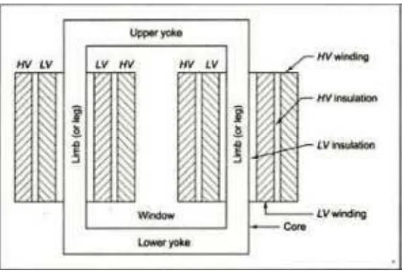
Figure 2.1 shows concentric windings which are used for core?type transformers. These windings are further divided as follows [4]:
I. Cross?over winding: used for current up to 20A and suitable for high voltage windings of small transformers.
II. Helical winding: consists of rectangular strips wound in the form of helix and suitable for low voltage windings of large transformers. Extra insulation between layers is required in addition to insulation of conductors in order to use these coils for high voltage windings.
III. Continuous disc winding: consists of a number of flat strips wound spirally from inside (radially) outwards. To complete the windings or section of winding between the tappings, the length of used conductors must be sufficient. The conductors can be either single strip or a number of strips in parallel for robust construction for
each disc.
7
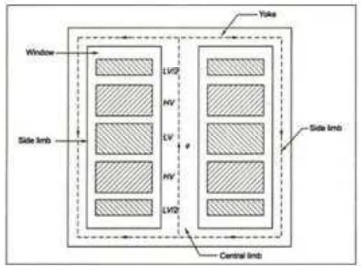
2<2<5<2 &%$- + %$ %*
Figure 2.2 shows sandwich windings used in shell type transformers. Each high voltage section lies between two low voltage sections when the high voltage and low voltage windings are split into a number of sections. Leakage can easily be controlled in sandwich coils. By proper division of windings, desired value of leakage reactance can be obtained.[4]
Figure 2.2: Sandwich Winding
Figure 2.2 Sandwich winding
2<2<8 - & &+ /
8
2<2<: % %$ %$ %*
Transformer cores are constructed predominantly from ferromagnetic material. The most commonly used material is iron, with the addition of small amounts of silicon
and other elements that help improve the magnetic properties and or lower losses. Other materials, iron oxides (ferrites), are used in high frequency transformer. The amorphous metals, generally consisting of iron, boron and other additions, are also used as cores for distribution transformer. All these materials are broadly classified as ferromagnetic and such as share many common properties, such as saturation magnetization or induction, hysteresis and a curie temperature above which they cease to be ferromagnetic [6].
Nickel iron alloys are produced in sheet form. Because of their malleability, they can be rolled extremely thin, resulting in very low eddy current losses so that they can be used in high frequency applications. Their saturation induction is lower than that silicon steel. Ferrite cores are made of sintered powder and generally have isotropic magnetic properties. They can be cast directly into the desired shape or machine after casting. They have extremely high resistivities that permit their use in high frequency applications. However, they have rather low saturations inductions.
Ideally, transformer core would carry the flux along the direction of highest permeability and in a closed path. Path interruptions caused by joints, which are occupied by low permeability air or oil, lead to poorer over all magnetic properties[6]. In addition, cutting or slitting can introduce localized stresses that degrade the magnetic properties. The higher loss can be accounted for in the design by multiplying the ideal magnetic circuit losses, usually provided by the manufacturer on a per unit weight basis, by a building
9
2<2<:<4 & ! & %
The performance of transformers also constrained by the magnetic flux limitations of the core. There are two factors for choosing the best core materials for current transformer which is based on accuracy and size of the current transformer [6]. The increasing of magnetic field force (mmf) does not result in proportional increases in magnetic field flux (Φ). The core flux may reach saturation levels during peak moments of the AC sine wave cycle when a transformer’s primary winding is overload from excessive applied voltage. The overload transformer will distort the wave shape from primary to secondary windings, creating harmonics in the secondary winding’s output. Special transformer known as peaking transformer produce brief voltage pulses near the peaks of the source voltage waveform. At voltage levels well below peak, the core is designed to saturate quickly and sharply. Figure 2.3 below show the voltage and flux waveforms for a peaking transformer.
![Figure 2.3: Voltage And Flux Waveforms For A Peaking Transformer [3]](https://thumb-ap.123doks.com/thumbv2/123dok/546907.64078/24.595.108.477.386.542/figure-voltage-flux-waveforms-peaking-transformer.webp)
