raf
TK2182 .M37 2010.
0000073380
Analysis of AC transformer and DC machines by using labview I Muhammad Asyraf Masrohe.
ANALYSIS OF AC TRANSFORMER AND DC MACHINES BY USING LABVIEW
Muhammad Asyraf bin Masrohe
"I hereby declared that I have read through this report entitled Analysis of AC Transformer and DC machines by using Lab VIEW and found that it has comply the partial fulfilment for awarding the degree of Bachelor of Electrical Engineering (Industrial Power)"
Signature
Supervisor's Name Puan Nur Hakimah Binti Ab. Aziz
ANALYSIS OF AC TRANSFORMER AND DC MACHINES
BY USING LABVIEW
MUHAMMAD ASYRAF BIN MASROHE
A report submitted in partial fulfilment of the requirements for the degree
of Electrical Engineering (Industrial Power)
Faculty of Electrical Engineering
UNIVERSITI TEKNIKAL MALAYSL\ MELAKA
iii
I declare that this report entitled "Analysis of AC Transformer and DC Machine by using
Lab VIEW'' is the result of my own research except as cited in the references. The report has not been accepted for any degree and is not concurrently submitted in candidature of any other degree.
Signature
ᄋᄋᄋᄋᄋᄋᄋᄋᄋᄋᄋᄋᄋセᄋᄋᄋᄋᄋᄋᄋᄋᄋᄋᄋᄋᄋᄋᄋᄋᄋᄋᄋᄋᄋᄋᄋᄋᄋᄋ@
Name Muhammad Asyraf bin Masrohe
iv
v
AKNOWLEDGEMENT
First of all I would like to thank my supervisor Puan Nur Hakimah binti Ab. Aziz
for all the help, guidance and support in the accomplishment of this project. I am also
thankful to En. Farhan bin Hanaffi for his ideas, opinions and advices for my project
development.
Not to forget my beloved family and friends for all the supportive motivations and
reminders in keeping this project always on the right track. Finally, thanks to those who
vi
ABSTRACT
An Electrical Machine subject is a compulsory subject for student of Faculty of Electrical
Engineering at UTeM. Among the main topics in this subject are AC Transformer and DC Machine. This project has been designed and developed by using Lab VIEW for developing
the graphical user interface (GUI) of AC transformer and DC machines analysis. This GUI could be used in the form of simulation for an electrical software application in laboratory session. It is also can be used as e-learning of teaching and learning process in terms on how to analyse practically through the software. This project has presented a virtual instrument (VI) of AC transformer and DC machine by using Lab VIEW which it is a user friendly programming language and easy to be learnt by new programmer. It practices the
user-friendly application which the user just needs to give a desired data for processing stage and output performance result. The VI consisted of 4 sections which are single phase transformer, three phase transformer, autotransformer and DC machines. These analyses focused on the performance of the AC transformer and DC machines and other aspect such as phasor diagram and power flow diagram. The Lab VIEW result have been verified and compared with manual calculation in order to ensure they are correct and reliable. These
vii
ABSTRAK
Subjek Mesin Elektrik ialah subjek wajib untuk pelajar di Fakulti Kejuruteraan Elektrik, UTeM. Antara topik utama dalam subjek ini ialah Pengubah arus ulang alik dan Mesin arus terus. Projek ini telah merekabentuk dan membangunkan sebuah paparan pengguna
bergraftk (GUI) untuk analisis Pengubah arus ulang alik dan mesin arus terus dengan menggunakan LabVIEW. GUI ini boleh dijadikan sebagai sebuah simulasi mengenai
viii
TABLES OF CONTENTS
CHAPTER TITLE PAGE
AKNOWLEDGMENT
v
ABSTRACT
vi
ABSTRAK
vii
TABLE OF CONTENTS
viii
LIST OF TABLE
xii
LIST OF FIGURES
xiii
LIST OF SYMBOL
xvi
LIST OF ABBREVIATIONS xvii
LIST OF APPENDICES
xviii
1 INTRODUCTION 1
2 LAB VIEW
s
2.1
OVERVIEW OF LABVIEW5
2.2
MAIN PARTS OF VI6
2.2.1
FRONT PANEL6
2.2.2
FRONTPANELTOOLBAR 72.2.3
CONTROL PALETTE 82.2.4
BLOCK DIAGRAM 92.2.5
BLOCK DIAGRAM TOOLBAR 10ix
CHAPTER TITLE PAGE
3 ELECTRICAL MACHINE 12
3.1
AC SINGLE PHASE TRANSFORMER12
3.1.1
OPEN CIRCUIT TEST ANDSHORT CIRCUIT TEST
13
3.1.2
PHASOR DIAGRAM15
3.1.3
POWER FLOW DIAGRAM15
3.1.4
VOLTAGE REGULATION16
3.1.5
EFFICIENCY16
3.2
AUTOTRANSFORMER16
3.3
THREE PHASE TRANSFORMER18
3.3.1
THREE PHASE TRANSFORMERCONNECTION
18
3.4
DC MACHINE19
3.4.1
DC GENERATOR19
3.4.2
DC MOTOR21
4 LITERATURE REVIEW 22
4.1
INTRODUCTION22•
4.2
THESIS REVISION22
4.3
GRAPHICAL PROGRAMMING IN Lab VIEW23
4.4
ELECTRICAL MACHINE TOPICS26
5
METHODOLOGY
27
5.1
METHODOLOGY27
5.2
GENERAL FLOW CHART28
5.2.1
IDENTIFY OBJECTIVE ANDSCOPE PROJECT
29
5.2.2
PRELIMINARY STUDY29
X
CHAPTER TITLE PAGE
5.3 FLOW CHART OF DATA ANALYSIS 32
5.3.1 SINGLE PHASE TRANSFORMER
ANALYSIS 34
5.3.1.1 FLOW CHART OF SINGLE
PHASE TRANSFORMER 37
5.3.2 THREE PHASE TRANSFORMER
ANALYSIS 38
5.3.2.1 FLOW CHART OF THREE
PHASE TRANSFORMER 39
5.3.3 AUTOTRANSFORMER
ANALYSIS 40
5.3.3.1 FLOW CHART OF
AUTOTRANSFORMER 42
5.3.4 DC MACHINE ANALYSIS 43
5.3.4.1 FLOW CHART OF
DC MACHINE 44
6 RESULT, ANALYSIS AND DISCUSSION
45
6.1 RESULT OF VI DEVELOPMENT 45
6.2 ANALYSIS OF SINGLE PHASE
TRANSFORMER 46
6.3 ANALYSIS OF THREE PHASE
TRANFORMER 53
6.4 ANALYSIS OF AUTOTRANSFORMER 60
6.5 ANALYSIS OF DC MACHINE 66
6.6 DISCUSSION OF ANALYSIS RESULT 70
6.7 SURVEY ON ANALYSIS OF
AC TRANSFORMER AND DC MACHINE 71
CHAPTER
7
REFERENCES APPENDIX A APPENDIXB
TITLE
6.7.2 DISCUSSION
6.7.3 SURVEY 1 6.7.4 SURVEY 2
6.7.5 SUMMARY
CONCLUSION AND RECOMMENDATION
7.1 CONCLUSION
7.2 RECOMMENDATION
PAGE
71
72
74
77
78
78
79
81
83
xii
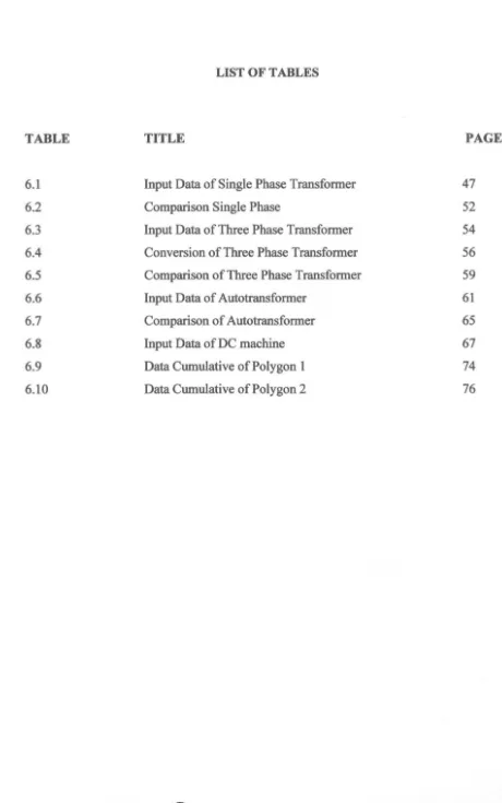
LIST OFT ABLES
TABLE TITLE PAGE
6.1 Input Data of Single Phase Transformer 47
6.2 Comparison Single Phase 52
6.3 Input Data of Three Phase Transformer 54
6.4 Conversion of Three Phase Transformer 56
6.5 Comparison of Three Phase Transformer 59
6.6 Input Data of Autotransformer 61
6.7 Comparison of Autotransformer 65
6.8 Input Data of DC machine 67
6.9 Data Cumulative of Polygon 1 74
[image:13.606.53.513.67.802.2]xiii
LIST OF FIGURES
FIGURE TITLE PAGE
2.1
Duel Display Multimeter5
2.2
Front Panel6
2.3
Front Panel Toolbar7
2.4
Broken Run Button8
2.5
Control Panel8
2.6
All Control sub palette9
2.7
B lock Diagram of Lab VIEW9
2.8
Block Diagram Toolbar 102.9
Function Palette 112.10
All Function sub palette 113.1
The Primary Side & Secondary Side 133.2
Open Circuit13
3.3
Short Circuit14
3.4
Lagging Power Factor15
3.5
Power Flow Diagram15
3.6
Step Down Autotransformer Connection17
3.7
A Three Phase Transformer18
3.8
Elementary DC motor with commutator19
4.1
Equivalent Impedance by G Programming24
4.2
Equivalent Impedance by C Programming25
4.3
Power system delivery26
5.1
General Flow Chart28
5.2
Front Panel Layout30
5.3
Block Diagram31
5.4
Flow Chart of Data Analysis32
xiv
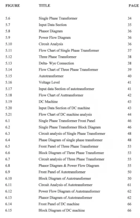
FIGURE TITLE PAGE
5.6
Single Phase Transformer34
5.7
Input Data Section35
5.8
Phasor Diagram36
5.9
Power Flow Diagram36
5.10
Circuit Analysis36
5.11
Flow Chart of Single Phase Transformer37
5.12
Three Phase Transformer38
5.13
Delta- Wye Connection38
5.14
Flow Chart of Three Phase Transformer39
5.15
Autotransformer40
5.16
Voltage Level41
5.17
Input data Section of autotransformer41
5.18
Flow Chart of Auttransformer42
5.19
DC Machine43
5.20
Input Data Section of DC machine43
5.21
Flow Chart of DC machine analysis44
6.1
Single Phase Transformer Front Panel46
6.2
Single Phase Transformer Block Diagram46
6.3
Circuit analysis of Single Phase Transformer48
6.4
Phase Diagram of single phase transformer48
6.5
Front Panel of Three Phase Transformer53
6.6
Block Diagram of Three Phase Transformer53
6.7
Circuit analysis of Three Phase Transformer55
6.8
Phasor Diagram & Power Flow Diagram55
6.9
Front Panel of Autotransformer50
6.10
Block Diagram of Autotransformer50
6.11
Circuit Analysis of Autotransformer61
6.12
Power Flow Diagram of Autotransformer62
6.13
Phasor Diagram of Autotransformer62
6.14
Front Panel of DC machine66
XV
FIGURE TITLE PAGE
6.16 Speed-Torque characteristic graph 67
6.17 Proven on Graph 69
6.18 Magnetization Curve of DC machine 70
6.19 Interest Bar Chart 72
6.20 Lesson Understanding Bar Chart 73
6.21 Effectiveness Polygon 75
xvi
LIST OF SYMBOL
v
Voltagen
Ohmy Admittance
R Resistance
X Reactance
I Current
z
Impedancep ·Power
s
Apparent PowerPf Power Factor
Th Speed
UTeM VI GUI
LIST OF ABBREVIATIONS
Universiti Teknikal Malaysia Melaka Virtual Instrument
Graphical User Interface
FIGURE
A
B
LIST OF APPENDICES
TITLE
SURVEY FORM GANTT CHART
xviii
PAGE
83
CHAPTER I
INTRODUCTION
1.1 PROJECT BACKGROUND
In faculty of electrical engineering, UTeM, Electrical Machine subject is being a
compulsory subject for students. Under Electrical Machine subject, there have three
sections which are Transformer, AC machines and DC machines. This project is to develop
a virtual instrument (VI) on two topics of Electrical Machine subject which are
Transformer and DC Machine. The VI will be focused on equivalent circuit, power flow
diagram, phasor diagram and performance analysis such as voltage regulation and
efficiency. This project will use Lab VIEW software as their main platform of VI because it
can be used to handle data acquisition in easier way compared to text based programming
language. This project also hopefully could be a teaching aid for electrical machine subject
inUTeM.
1.2 PROBLEM STATEMENT
Student of Faculty of Electrical Engineering, UTeM, learnt about AC transformer
and DC machines deeply especially in the aspect of basic knowledge about it. The students
need to understand the concept, the operation and the analysis of those things before
applying them in the real work. The lecturers teach the students on how to analyse through
a manual calculation and build up the phasor diagram from that calculation. Some
calculation may be different as certain condition is changed which student need to
recalculate based on the new condition. However, this manual calculation process takes a
longer time and it has a lot of formulas that the students need to apply during calculation.
Sometimes errors also can be happen and the output result will be not accurate in the way
2
In the aspect of knowledge understanding, students have problem to visualize the total flow of power in the machines and phasor diagram construction. The existence of voltage drop within machines is influenced by power factor that can be visualized in the form of phasor diagram. Some student may have problem to concentrate in class, thus, an alternative of teaching and learning style should be introduce to help them to study by themselves.
An efficiency teaching aid is a suitable teaching aid which help student for improving their knowledge and understanding in Electrical Machine subject. The good teaching aid must have the required aspect such as a machines model with the animation related to the performance analysis of transformer and machine which included in syllabus of that subject.
3
1.2 PROJECT OBJECTIVE
The Graphical User Interface (GUI) is the main study in this project. The project
began with the revision and designs of the GUI of analysis for AC transformer and DC
machines. The manual calculation must be accurate and correct before programming stage
can be started. Finally, this VI is developed to achieve the following objectives:
• To analyze the performance of AC transformer and DC machines in various
conditions as introduced in Electrical Machine subject.
• To develop an effective teaching aid for lecturers in classroom and laboratory.
• To develop an interactive learning aid that can be used by students for studying
Electrical Machine subject by themselves.
1.3 PROJECT SCOPE
This study focuses on development of Graphical User Interface (GUI) by using
Virtual Instrument (VI). Through this project, Lab VIEW is used as the main platform for
VI. In order to make the development of GUI is carried on clearly, the analysis of AC
transformer and DC machines need to be reviewed and identified.
In short the project scopes are listed as follow:
• To perform the analysis of single phase transformer, the suitable performance are
focused more on circuit analysis in every parts, power flow analysis and power
flow diagram depending on circuit and power flow condition.
• For the analysis of three phase transformer, the focus is more on the transformer
connection type such as delta and wye connection in between primary and
4
• About the analysis on autotransformer, the focus is stressed on the step up or step
down connection type and both of those connection type are different either in
primary and secondary winding condition.
• For the DC machine, the focus stressed on the torque-speed characteristic graphs.
1.5 PROJECT OUTLINE
This report on "Analysis of AC Transformer and DC machines by using
Lab VIEW" is divided into 7 chapters. Chapter 1 introduces the general background of this
research, the problem statement, project objectives, as well as the project scope. Also, it
offers an overall view of the project outline.
Chapter 2 is a compilation of required information and a basic knowledge of
Lab VIEW software. It included the information as a turnkey needed by this project.
Chapter 3 is a theory of electrical machine which related with this project. The
topic chosen is AC Transformer and DC machine.
Chapter 4 is a literature review on past studies related to this project. Only simple
background theory included.
Chapter 5 explains about the methodology used in this project from starting stage
until ending stage. The detail explanation about the project milestones has been written
clearly.
Chapter 6 presents the result and the analysis of the project. This chapter is also
discussing on the approved VI analysis by manual calculation and the survey by personal
which have used this VI.
Finally, Chapter 7 presents the conclusion of a LabVIEW as E-Learning for
CHAPTER2
LAB VIEW
2.1 OVERVIEW OF LABVIEW
Lab VIEW is short form for Laboratory Virtual Instrument Engineering
Workbench. The concept of the virtual instrument (VI) practices a real application into the simulation. It is mention that 'the objective in virtual instrumentation is to use a
general-purpose computer to mimic real instruments with their dedicated control and
display, but with the added versatility that comes with software' [1].
Instead of buying a strip-chart decoder, an oscilloscope, and a spectrum analyser to
build up a real duel display multimeter, only in purposing to get a output result, Lab VIEW
can simulate all of these instruments through build a custom of duel display multimeter by
[image:24.615.72.514.67.423.2]its VI efficiently and having only the necessary features as shown in Figure 2.1.