G. Tan et al. (Eds.): AsiaSim 2013, CCIS 402, pp. 231–242, 2013. © Springer-Verlag Berlin Heidelberg 2013
A Yaw Rate Tracking Control of Active Front Steering
System Using Composite Nonlinear Feedback
M. Khairi Aripin1,*, Y.M. Sam2, A.D. Kumeresan2, Kemao Peng3, Mohd Hanif Che Hasan4, and Muhamad Fahezal Ismail5
1
Faculty of Electrical Engineering, Universiti Teknikal Malaysia Melaka, Melaka, Malaysia [email protected]
2
Faculty of Electrical Engineering, Universiti Teknologi Malaysia, Johor, Malaysia {yahaya,kumeresan}@fke.utm.my
3
Temasek Laboratory, National University of Singapore, Singapore [email protected]
4
Faculty of Engineering Technology, Universiti Teknikal Malaysia Melaka, Melaka, Malaysia [email protected]
5
Industrial Automation Section, Universiti Kuala Lumpur Malaysia France Institute, Selangor, Malaysia
Abstract. In this paper, the composite nonlinear feedback (CNF) technique is applied for yaw tracking control of active front steering system with the objec-tives to improve the transient performance of yaw rate response. For lateral and yaw dynamics analysis, nonlinear and linear vehicle models are utilized as actual vehicle plant and for controller design respectively. The designed con-troller is evaluated using J-turn cornering manoeuvre condition in computer simulation. The simulation results demonstrate that the application of CNF for yaw rate tracking control improves the yaw stability and vehicle handling performances.
Keywords: composite nonlinear feedback, yaw rate control, active front steering, vehicle yaw stability.
1
Introduction
Yaw stability control system is one of the approaches utilized for lateral dynamics motion control of road vehicles. The vehicle yaw rate is an important variable to be controlled to ensure vehicle lateral stability. Thus, the main objective of yaw stability control is to ensure the proposed controller is able to track a desired yaw rate i.e. the actual response of yaw rate is close to a desired response that is generated by refer-ence model. The yaw rate tracking control can be realized by implementing an active front steering (AFS) for vehicle handling improvement especially during low to mid-range of lateral acceleration. In AFS system, the front wheel steer angle is a sum of steer angle commanded by the driver and corrective steer angle that is generated by the proposed controller.
*
Various control strategies have been developed and implemented for vehicle yaw stability control based on AFS [1-8]. The yaw stability controller based on sliding mode and back stepping algorithm is designed to ensure the vehicle yaw rate follow its reference [1]. As implemented in [2], the model predictive control (MPC) tech-nique is adapted for yaw stability control based on active differential braking to im-prove the vehicle stability during critical manoeuvre while in [3], the mixed-sensitivity minimization technique is applied as feedback control loop to track the desired yaw rate as close as possible. To cater the uncertainties of vehicle parameters, the robust yaw control is designed based on second order sliding mode control (SOSM), internal mode control (IMC) and these control performances was compared each other as discussed in [4-6]. As reported in [7], the yaw rate control of active front steering is designed based on fuzzy logic control to improve the vehicle stabil-ity. Similarly, the yaw rate controller is developed based on fuzzy logic control in order to track the desired yaw rate as discussed in [8]. In point of view of tracking control, the transient response performance is vital. However, based on above review, the improvement of transient response performance in yaw rate tracking control is not well emphasized and an appropriate control technique should be proposed for this purpose.
The composite nonlinear feedback (CNF) control is one of nonlinear control nique that has been developed in last decade based on state feedback law. This tech-nique was introduced in [9] for tracking control of 2nd order linear system had been improved for higher order MIMO linear system in [10]. It was further explored and extended for linear system with actuator nonlinearities in [11], general multivariable system with input saturation in [12], hard disk drive servo system and servo position-ing system with disturbance in [13-16]. Recently, the CNF have been applied in vehi-cle dynamics control particularly for active suspension system in order to improve suspension deflection, velocity of car body, tire deflection, velocity of car wheel and body acceleration [17]. In principle, the use of CNF control could improve the per-formance of transient response based on variable damping ratio concept. The CNF control keep low damping ratio during transient and varied to high damping ratio as the output response close to the reference set point. To realize this concept, the CNF control that consists of linear and nonlinear feedback control law is designed in three important steps which will be discussed later. Therefore, based on previous studies and above discussion, an advantages of CNF control technique especially for improv-ing transient response of trackimprov-ing control is not yet been examined for vehicle yaw rate tracking control and should be further explored.
In this paper, the CNF control is introduced for vehicle yaw rate tracking control of AFS system. The lateral and yaw dynamics of nonlinear two track model is used as vehicle plant and linearized single track model is utilized for the controller analysis and design. To evaluate the performance of propose controller, the vehicle handling test of cornering manoeuvre are performed in computer simulation.
control technique. In Section 2, the dynamics of a nonlinear vehicle model and a lin-ear single track model are discussed. The theory of CNF control and design proce-dures are explained in Section 3. The simulation results and discussion are presented in Section 4. Finally, a conclusion and future works is presented in Section 5.
2
Vehicle Dynamic Models
In this section, dynamic equations of a nonlinear two track vehicle model and a linear single track model are presented and discussed. These two models are constructed for vehicle plant and controller design respectively, whose performance is analyzed using a computer simulation tool.
2.1 Nonlinear Two Track Model
A nonlinear two track model as shown in Figure 1 is used as the actual vehicle plant for controller evaluation. The nonlinear dynamics for lateral and yaw motion are de-scribe as in equations (1) and (2) respectively;
(
F F)
rmv y− y −
= β β
β 1 cos sin (1)
[
f y f y f x f x f r y y z]
z
M F F l F
F F
F l I
r= 1 ( 1cosδ + 2cosδ + 1sinδ + 2sinδ )− ( 3+ 4)+ (2)
where the sum of longitudinal forces Fy, sum of lateral forces Fxand yaw
mo-ment Mzin the above equations are given as follows;
) (
sin ) (
cos f x1 x2 f y1 y2
y F F F F
F = + − +
δ
δ
(3)) (
cos ) (
sin f x1 x2 f y1 y2
y F F F F
F = + + +
δ δ (4)
(
1cos 2cos 1sin 2sin 3 4)
2 x f x f y f y f x x
z F F F F F F
d
M =
δ
−δ
−δ
+δ
+ − (5)The vehicle parameters involved in equations (1) - (5) above are vehicle speed v, vehicle mass m, vehicle width track d, distance of front axle to center of gravity (CG) lf and distance of rear axle to CG lr . The front wheel steer angle δf is
the input to the system while the nonlinear longitudinal tire forces Fxiand lateral tire forces Fyican be described using Pacejka tire model. Notice that the vehicle speed v
d 2 x F 2 y F 1 y F 1 x F 4 x F 3 x F 4 y F 3 y F x v v r d β f l r l y
v Mz
f
[image:4.595.231.467.550.650.2]δ δf
Fig. 1. Two track model
2.2 Tire Model
In the equations (1) - (5) above, the longitudinal tire force Fxiand lateral tire force
yi
F may exhibit nonlinear characteristics. The pure longitudinal and lateral tire forces
during pure side slip can be described using the Pacejka tire model as described in the following equations (6) and (7) respectively
[
tan ( . ( . tan ( . )))]
sin xi 1 xi i xi xi i 1 xi i
xi
xi D C B E B B
F = − λ − λ − − λ (6)
[
tan ( . ( . tan ( . )))]
sin yi 1 yi f yi yi f 1 yi f
yi
yi D C B E B B
F = − α − α − − α (7)
where the parameters Dxi,Dyi,Cxi,Cyi,Bxi,Byi,Exiand Eyi are known as tire model
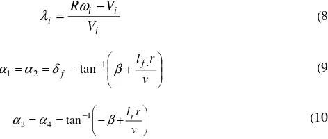
parameters that depending on tire characteristics, road surface and vehicle conditions while λi and αi are longitudinal wheel slip and tire sides slip angle respectively that given by the following equations
i i i i V V R − = ω
λ (8)
+ − = = − v r lf f . 1 2
1 α δ tan β
α (9)
+ − = = − v r lr β α α 1 4
3 tan (10)
2.3 Linear Single Track Model
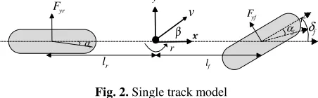
To design the controller for yaw rate tracking control of active front steering, a linear single track model as shown in Figure 2 is utilized. This model is linearized from the two track nonlinear vehicle model based on few main assumptions: tire force operates in linear region, very small of front steer angle δfand vehicle side slip β ,vehicle
speed v is constant and two tires at front and rear axle are lumped into single tire at the centre line of vehicle [18].
f l
r
l
r
yf
F
v
β δf
y
f
α
r
α
yr
[image:5.595.183.409.257.327.2]F
Fig. 2. Single track model
The dynamics equation for the lateral and yaw motions are described as follows
yr
yf F
F r
mv(
β
+ )= + (11)yr r yf f
zr l F l F
I = − (12)
As assumed above which tire forces are operates in linear region, front lateral tire force Fyf and rear lateral tire forceFyr are exhibit linear characteristics as described
in the following equations
f f yf C
F = α (13)
r r yr C
F = α (14)
where Cf and Cr are front and rear tire cornering stiffness respectively. For linear
tire forces, sideslip angle of front and rear tire are given in the equation (15) and (16) respectively as follows
v r lf
f f =δ −β−
α (15)
v r lr
r =−
β
+α
(16)f z f f f z r r f f z f f r r f f r r r f I l C mv C r v I l C l C I l C l C mv l C l C mv C C r Bu Ax x δ β β + − − − − + − − − = + = 2 2 2 1 (17)
2.4 Yaw Rate Reference Model
The main objective in yaw rate tracking control of active front steering is to bring the actual response of vehicle yaw rate close to desired response. The desired yaw rate
response is determined as a function of vehicle speed v and front wheel steer angle
f
δ in steady state condition as follows
f u d v k l v
r .δ
2
+
= (18)
where
k
uis known as cornering stability factor and define as followsr f r f f f r r u C C l l C l C l m k ) ( ) ( + −
= (19)
However, due to lateral acceleration of the vehicle in g unit could not exceed the maximum road friction coefficient
µ
, the steady state value of yaw rate must be lim-ited as express in the following equationv g
rss ≤
µ
(20)3.1 CNF Control Design
A linear time-invariant continuous system with input saturation is considered as follows
Cx y
x x u Bsat Ax
x o
=
= +
= ( ) (0)
(21)
where x∈ℜn, u∈ℜ, y∈ℜ are the state variable, control input and controlled
output respectively. A, B and C are constant system matrices with appropriate
di-mensions and sat:ℜ→ℜrepresent actuator saturation defined as follows
}
{
u u uu
sat( )=sgn( )min max, (22)
with umax is saturation level of the input. To design and apply the CNF control, the
following assumptions of system matrices are considered;
1.(A,B) is controllable/stabilizable
2.(A,C) is observable/detectable
3.(A, B, C) is invertible and has no zero at s=0
To design the CNF for tracking control of step input without large overshoot and without adverse actuator saturations effects, the CNF control laws is design in three important steps. The details for step by step design process are discussed as follows
Step 1: design a linear feedback control law
Gr Fx
uL = + (23)
where r is step input reference and F is feedback matric chosen such that
A
+
BF
is anasymptotically stable matrix and closed loop system C(sI−A−BF)−1Bhas certain
desired properties such as small damping ratio.G is a scalar which given as follows
1 1
] ) (
[ + − −
−
= C A BF B
G (24)
The selection of matric F is not unique where it can be determined using linear
con-trol design techniques such as pole placement assignment.
Step 2: design a nonlinear feedback control law
) ( ) ,
( e
N r y BP x x
u =ρ ′ − (25)
where
ρ
(r,y)is nonpositive function locally Lipschitz in y that used to change thedamping ratio of closed loop system as output approaches the step command input. 0
>
W BF A P P BF
A+ )′ + ( + )=−
( (26)
for some given W >0and xeis defined as
r
G
x
e:
=
e (27)BG BF A
Ge:=−( + )−1 (28)
The nonlinear function
ρ
(r,y)is not unique. To adapt the variation of trackingtar-get, the nonlinear function
ρ
(r,y)in [19,20] is utilized as followsr y
o
e y r
p( , )=−
γ
−ϕϕ − (29)where
= ≠ −
=
r y
r y r y
o o o
o
, 1
, 1
ϕ (30)
Step 3: complete CNF control law
Both control laws in step 1 and 2 are combined to form the complete CNF control law as follows
) ( ) ,
( e
N
L u Fx Gr r y BP x x
u
u= + = + +ρ ′ − (31)
3.2 Tuning Parameters of Nonlinear Function
The selection of design parameters of nonlinear function is essential for CNF control design so that the performance of closed loop system is improved as the controlled output approaches the reference set point. In this paper, the parameter
γ
andϕ
of nonlinear function are tuned according to the method as proposed in [20] as follows1.choose the desired steady state damping ratio ξss
2.determine
γ
by letting the steady state system has a damping ratio of ξss3.determine an optimal
ϕ
by solving minimization some appreciable criterions of in-tegral of absolute error (IAE) and inin-tegral of time-multiplied absolute value of er-ror (ITAE) which given by equations
∞0
minϕ edt or
∞
0
minϕ tedt (32)
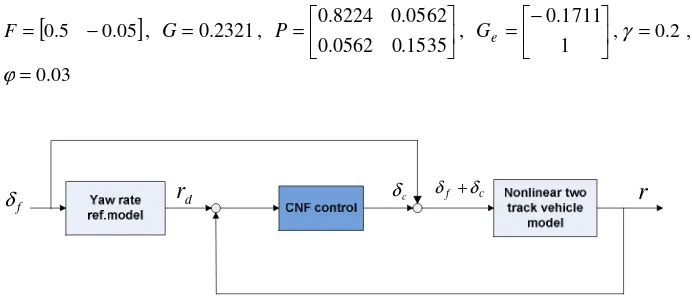
3.3 Active Front Steering Based on CNF Control
The AFS based on the CNF control technique for yaw rate tracking control is illus-trated in Figure 3. The front wheel steer angle is a sum of steer angle commanded by the driver, δf and corrective steer angle, δc that generated by the CNF control.
Based on vehicle parameters and linear single track model as discussed previously, the parameters of CNF control are obtained as follows
[
0.5 −0.05]
=
F , G=0.2321,
=
1535 . 0 0562 . 0
0562 . 0 8224 . 0
P ,
− =
1 1711 . 0 e
G ,γ =0.2,
03 . 0
=
ϕ
f
[image:9.595.125.471.244.396.2]δ
r
d δc δf +δcr
Fig. 3. Active front steering based CNF control
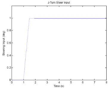
4
Simulation Results
The computer simulation of AFS based on the CNF control for yaw rate tracking control is conducted in Matlab/Simulink. The vehicle parameters used are taken from [21] as follows;
kg
m=1704.7 , Iz =3048.1kgm2 , lf =1.035m, lr =1.655m, Cf =105,800N ,
N
Cr =79,000 , d=1.54m
Fig. 4. J-turn steer input at 1°of steer angle
Fig. 5. Yaw rate response of J-turn manoeuvre at
1
°
steer angle [image:10.595.148.462.497.639.2]Table 1. Transient response parameters of J-turn manoeuvre controllers amplitude % OS tr (t) ts(t)
CNF Nil 0 0.0524 0.107
PID 7.57 7.10 0.137 0.46
uncontrolled 7.39 4.53 0.299 1.03
From the Figures 5 and 6, it is observed that the CNF control could track the yaw rate reference with fast transient response compared to PID controller and uncon-trolled vehicle. The performances of transient response parameters of this valuation are tabulated in Table 1.
The simulation of AFS based on the CNF control technique has been presented. From Table 1, it is observed that the yaw rate response with the CNF control tech-nique have no maximum peak of amplitude i.e. 0% overshoot compared to PID controller and uncontrolled response that obtained 7.1% and 4.53% overshoot respec-tively. In term of rise timetr, the CNF control performed better with 0.0524s which is obviously fastest than PID controller i.e. 0.137s and 0.299s of uncontrolled response. The CNF control also achieves fastest sampling time ts i.e. 0.107s compared to 0.46s of PID controller and 1.03s of uncontrolled response.
5
Conclusion
A new technique for vehicle yaw rate tracking control of active front steering is pro-posed based on the composite nonlinear feedback (CNF) control scheme. From the results obtained, it is shown that the CNF control is capable to achieve fast response of yaw rate tracking control where it is able to track the desired yaw rate with mini-mum overshoot and fast settling time for a J-turn cornering manoeuvre. As a conclu-sion, the CNF control is able to improve the transient response of vehicle yaw rate. For future works, the CNF control technique will be evaluated with other cornering manoeuvre. It will improve to cater external disturbances such as crosswind and un-certainties of vehicle parameters. Co-simulations with vehicle dynamics software such as CarSim will be conducted to validate the proposed controller.
References
1. Zhou, H., Liu, Z.: Vehicle Yaw Stability-Control System Design Based on Sliding Mode and Backstepping Control Approach. IEEE Transactions on Vehicular Technology 59, 3674–3678 (2010)
2. Zhou, H., Liu, Z.: Design of Vehicle Yaw Stability Controller Based on Model Predictive Control. In: IEEE Intelligent Vehicles Symposium, pp. 802–807. IEEE Press, Xian (2009) 3. Cerone, V., Milanese, M., Regruto, D.: Yaw Stability Control Design Through A
Mixed-Sensitivity Approach. IEEE Transactions on Control Systems Technology 17, 1096–1104 (2009)
5. Canale, M., Fagiano, L., Ferrara, A., Vecchio, C.: Vehicle Yaw Control via Second-Order Sliding-Mode Technique. IEEE Transactions on Industrial Electronics 55, 3908–3916 (2008)
6. Canale, M., Fagiano, L., Milanese, M., Borodani, P.: Robust Vehicle Yaw Control Using An Active Differential and IMC Techniques. Control Engineering Practice 15, 923–941 (2008)
7. Li, Q., Shi, G., Lin, Y., Wei, J.: Yaw Rate Control of Active Front Steering Based on Fuzzy-Logic Controller. In: Second International Workshop on Education Technology and Computer Science, Wuhan, pp. 125–128 (2010)
8. Tekin, G., Ünlüsoy, Y.S.: Design and Simulation of an Integrated Active Yaw Control System for Road Vehicles. International Journal of Vehicle Design 52, 5–19 (2010) 9. Lin, Z., Pachter, M., Ban, S.: Toward Improvement of Tracking Performance - Nonlinear
Feedback for Linear Systems. International Journal of Control 70, 1–11 (1998)
10. Turner, M.C., Postlethwaite, I., Walker, D.J.: Non-Linear Tracking Control for Multivari-able Constrained Input Linear Systems. International Journal of Control 73, 1160–1172 (2000)
11. Chen, B.M., Lee, T.H., Peng, K., Venkataramanan, V.: Composite Nonlinear Feedback Control for Linear Systems With Input Saturation: Theory and an Application. IEEE Transactions on Automatic Control 48, 427–439 (2003)
12. He, Y., Chen, B.M., Wu, C.: Composite Nonlinear Control with State and Measurement Feedback for General Multivariable Systems with Input Saturation. Systems and Control Letters 54, 455–469 (2005)
13. Lan, W., Thum, C.K., Chen, B.M.: A Hard-Disk-Drive Servo System Design Using Com-posite Nonlinear-Feedback Control with Optimal Nonlinear Gain Tuning Methods. IEEE Transactions on Industrial Electronics 57, 1735–1745 (2010)
14. Cheng, G., Peng, K.: Robust Composite Nonlinear Feedback Control with Application to A Servo Positioning System. IEEE Transactions on Industrial Electronics 54, 1132–1140 (2007)
15. Cheng, G., Jin, W.: Parameterized Design of Nonlinear Feedback Controllers for Servo Positioning Systems. Journal of Systems Engineering and Electronics 17, 593–599 (2006) 16. Peng, K., Chen, B.M., Cheng, G., Lee, T.H.: Modeling and Compensation of
Nonlineari-ties and Friction in A Micro Hard Disk Drive Servo System with Nonlinear Feedback Con-trol. IEEE Transactions on Control Systems Technology 13, 708–721 (2005)
17. Ismail, M.F., Sam, Y.M., Peng, K., Aripin, M.K., Hamzah, N.A.: A Control Performance of Linear Model and The Macpherson Model for Active Suspension System using Compo-site Nonlinear Feedback. In: IEEE International Conference on Control System, Compu-ting and Engineering, Penang, pp. 227–233 (2012)
18. Jazar, R.N.: Vehicle Dynamics: Theory and Application. Springer, Heidelberg (2008) 19. Lan, W., Thum, C.K., Chen, B.M.: Optimal Nonlinear Gain Tuning of Composite
Nonli-near Feedback Controller and its Application to A Hard Disk Drive Servo System. In: 48th IEEE Conference on Decision and Control Held Jointly with 28th Chinese Control Confe-rence, Shanghai, pp. 3169–3174 (2009)
20. On Selection of Nonlinear Gain in Composite Nonlinear Feedback Control for a Class of Linear Systems. In: 46th IEEE Conference on Decision and Control, pp. 1198-1203. New Orleans (2007)