Identification of Intelligent Controls in Developing Anti-Lock Braking System
IDENTIFICATION OF INTELLIGENT CONTROLS IN DEVELOPING ANTI-LOCK BRAKING SYSTEM
Rau, V. *1, Ahmad, F.2, Hassan, M.Z.3, Hudha, K.4
1, 2, 3Department of Automotive, Faculty of Mechanical Engineering, Universiti Teknikal Malaysia Melaka,
Durian Tunggal, 76100 Melaka, Malaysia.
4Faculty of Mechanical Engineering, Universiti Pertahanan Nasional Malaysia (UPNM),
Kem Sungai Besi, 57000 Kuala Lumpur, Malaysia.
Email: *[email protected]; 2[email protected]; 3[email protected], 4[email protected]
ABSTRACT: This paper presents about the development of an Antilock Braking System (ABS) using quarter vehicle model and a control structure is developed to represents an ABS and conventional braking model. Diferent type of controllers is proposed to develop the ABS model. Antilock braking system (ABS) is an important part in vehicle system to produce additional safety for driver. This system is known as one of the automobile’s active safety. In general, Antilock braking systems have been developed to reduce tendency for wheel lock and improve vehicle control during sudden braking especially on slippery road surfaces. In this paper, to deal with the strong nonlinearity in the design of ABS controller, an intelligent controller has been identiied. The controllers such as PID and Fuzzy Logic are proposed to control the stopping distance and longitudinal slip of the wheel. Comparison results between these two controllers generated using Matlab SIMULINK.
KEYWORDS: Antilock Braking System, quarter vehicle model, PID controller, Fuzzy logic controller, Matlab Simulink.
1.0 INTRODUCTION
now becomes one of the high priorities for ground vehicle because of its capability to help the drivers to stop the vehicle in a shorter distance in the safest way. ABS is to manipulate the wheel slip so that a maximum friction force is obtained and the steering stability is maintained. This is to allow the vehicle to stop in the shortest distance possible while maintaining the directional control. It is well known that the friction
coeicient is a nonlinear function of the slip. The ideal goal of the control
design is to regulate the wheel velocity. The ABS function is based on the regulating wheel speed of a vehicle and maintaining the longitudinal slip of the vehicle. When braking force is applied to a rolling wheel, the slip conditions occurred. The wheel circumferential velocity (Vw) will be less than the vehicle velocity (Vv). Slip (λ) is deined as the
diference between vehicle velocity and wheel circumferential velocity, normalized to vehicle velocity. The longitudinal slip can be deined as:
(1)
The lateral coeicient of friction approaches at zero slip and start to
decrease once the wheel slip increases. The lateral stability, steering ability and the direction of the vehicle provides lateral friction. The
longitudinal coeicient of friction is zero at zero slip. If braking force is
not quickly reduced at this point, the reduction in road force leads to a rapid increase in slip and eventual lockup.
Figure 1: Coeicient of friction vs wheel slip [3]
Most control strategies for ABS deine their main objective as maintaining slip near a value of 0.2 throughout the braking trajectory. Base on the Figure 1, before reaching the wheel slip, s= 0.2, the coeicient of friction is in stable condition. Where else, ater the s=0.2, the coeicient of friction
Identification of Intelligent Controls in Developing Anti-Lock Braking System
intelligent control has been developed to implement in the ABS control. The benchmark control, PID controller, is the conventional controller used before developing the high performance controller. But, there are a lot more advance controllers such as sliding mode, MRAC PID, fuzzy, fuzzy-neural, fuzzy-sliding mode, fuzzy-neural sliding mode, and hybrid controllers. This paper represents comparison between conventional controller PID and Fuzzy Logic Controller only.
There are some researches based on the antilock braking system
such as in [2], have developed antilock braking system for simpliied
vehicle/tire/road dynamics using genetic fuzzy controller. Other than
that, [3] have developed antilock braking system for simpliied vehicle dynamic model by using variable structure controller. Meanwhile [4],
used intelligent fuzzy control to develop the antilock braking system
as well. While in [5] improves the passive antilock braking system
using adaptive control. In this paper, a quarter vehicle brake modeling has been developed using Matlab Simulink. This model has been given input of step with 500 Nm of brake torque to obtain the results. The quarter vehicle brake model tested using the passive braking, conventional controller PID and advance controller which is Fuzzy controller. The output results such as wheel velocity, vehicle velocity, wheel slip and stopping distance is observed.
2.0
VEHICLE MODEL
Refer to the [1] “Simulation of Vehicle Longitudinal Dynamics”, the
brake modeling for a single wheel with quarter vehicle mass can derive in mathematical equations. A rotating wheel allows the driver to maintain steering control under heavy braking by preventing skid and allowing the wheel to continue to interact with the road surface as directed by driver steering inputs. Locking is occurred when the wheel has no rotational speed, but still displaces either longitudinally or laterally. Whereas, under normal braking condition, the wheel has minimal rotational speed while brake is applied to avoid the wheel
from skidding. Vehicle starts to slip when the wheels is locked ater a
heavy braking. This is because an excessive brake torque higher than or equal to the available road tractive torque.
2.1 Quarter Vehicle Equation
mathematical model. From this vehicle modelling, a control structure can be developed for the braking system of a wheel to control the wheel
slip and stopping distance [1].
: Longitudinal slip in function of vehicle speed and
Figure 2: Longitudinal slip in function of vehicle speed and wheel speed [1]
Hence the longitudinal force is
The longitudinal speed is
The longitudinal slip, , of the wheel is
(9) (10)
Identification of Intelligent Controls in Developing Anti-Lock Braking System
(11)
The value is obtained using the lockup table based on the experiment on normal road surface.
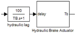
2.2 Hydraulic Brake Actuator
Hydraulic brake is a brake actuator used in the quarter vehicle brake
modeling. Hydraulic brake model will produce the brake torque, , during braking condition. Hydraulic brake system is current braking
mechanism used in all vehicles which contains brake luid (ethylene
glycol). The hydraulic brake system consists of:
(a) Brake pedal or lever mechanism
(b) Pushrod or actuating rod
(c) Master cylinder with pistons assembly (d) Hydraulic lines
(e) Brake caliper assembly which is combination of brake pad, piston and a rotor.
The pushrod is connected with the brake pedal mechanism which is operated by human during braking. The force given by the human (0 – 100%) will controlled the pressure in the braking mechanism. Based
on this Figure 3, brake pedal mechanism, a simpliied brake model can be derived [8].
Figure 3: Brake pedal mechanism
Figure 3: Brake pedal mechanism
= (12)
= (13)
= (14)
= (15)
Where by
= brake coefficient
= effective radius of disc brake
= Pressure in master cylinder
= Brake piston force
= Brake lever/pedal force
A. Case 1: Passive Braking System Without Abs
Simulation using Matlab can be developed based on the equation above. There are two conditions tested in this model which is braking
without ABS and with ABS. This modelling used to diferentiate the
wheel speed and wheel slip of the vehicle during passive braking and with ABS braking.
Figure 4: Signal Builder Input
Identification of Intelligent Controls in Developing Anti-Lock Braking System
B. Case 2: Braking System With Abs
PID Controller
PID controller is a one of the conventional controller developed to calculate the errors obtained from the actual plant model with the desired input. PID controller contained three types of parameters which
is adjustable according to the errors. Every parameter functioned in diferent technique in order to reduce the errors from plant model. PID
controller can be described as
a) P = proportional
b) I = Integral
c) D = Derivative
The P value represents the errors that occurred in current condition. Where else, I value represents the errors gathered from past condition and D value represents the prediction of future errors based on the changes occurred during current condition. Figure 5 shows the structure of PID controller.
Figure 5: Control Structure of PID controller
This controller is implemented into passive braking by replacing the signal builder input. The brake actuator added with hydraulic lag in the form of transfer function to represent delay from controller to the hydraulic response. The input for the hydraulic lag is the electrical current, i.
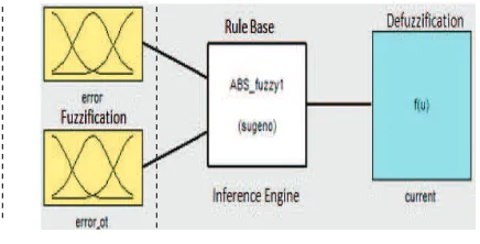
Fuzzy Logic controller
Every fuzzy controller is made up of three main components:
the fuzziication, rule base, and defuzziication mechanisms. The fuzziication mechanism function is to map the controller inputs
and assign a proper value μ (u) for each proper function forming the universes. Fuzzy rule base consists in assessing fuzzy rule set of the type, which has two main parts, the antecedent and the consequent.
IF e (t) IS …AND c(t) IS… THEN u (t)
The antecedent is before the word “THEN” and its function is to relate the controller input proper values to the consequent. Defuzziication is
the procedure through which the fuzzy rule set is assessed and a non-fuzzy or analog signal is assigned. The most frequently used method is
the area center, although there are methods like the irst maximum or
the maximum average.
and assign a proper value μ (u) for each proper function forming the universes. Fuzzy rule base
IF e (t) IS …AND c(t) IS… THEN u (t)
The antecedent is before the word “THEN” and its function is to relate the controller input proper
PID controller. PID controller function as a bench mark for fuzzy, it’s a conventional controller
Figure 7: Fuzzy logic control block
In this paper, Fuzzy Logic Controller is developed based on
Takagi-Sugeno-Kang (TSK) model [3]. There are two inputs given for this
controller which is obtained from the ABS model using PID controller. PID controller function as a bench mark for fuzzy, it’s a conventional controller and very easy to identify fuzzy parameters.
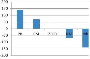
The maximum and minimum range inputs for fuzzy logic is deined
based on the PID controllers. The output of the fuzzy logic will be the electrical current which will be the input for the hydraulic lag transfer function. The input and output variables can be divided into 3 variables which is positive (POS), negative (NEG) and zero (ZERO). Where else, output variables is positive big (PB), positive medium (PM), zero (ZE), negative medium (NM) and negative big (NM). In order to improve
fuzziication speed, Gaussian function is chosen as the membership
Identification of Intelligent Controls in Developing Anti-Lock Braking System
Figure 8: Error input variables
Figure 9: Error dot input variables
Figure 10: Current Output Variable
Figure 10: Current Output Variable
The fuzzy logic is derived by using the mathematical model. The derivation is fuzzy logic is in exponential form. This model will include the spread, center and two inputs of Gaussian graph. The equation of
Gaussian Model is:
= (16)
Where
x = input of fuzzy (error, error_dot)
Vehicle braking model is developed in Matlab SIMULINK using the mathematical derivation. Quarter vehicle brake model is used to develop in the SIMULINK. At the same time, the hydraulic brake
actuator developed in SIMULINK. The technical speciications of the
quarter vehicle test rig are listed in Table 2.
Table 1: Simulation parameterTable 1: Simulation parameter
Symbol Value
4.0
SIMULATION RESULTS
Identification of Intelligent Controls in Developing Anti-Lock Braking System
Figure 11: Brake torque
Figure 12: Longitudinal slip
Figure 13: Wheel speed
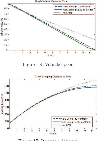
Figure 14: Vehicle speed
Figure 14: Vehicle speed
Figure 15: Stopping distance
Based on the results, quarter vehicle model using hydraulic brake model can be used to develop an antilock braking system. Active control such as PID and Fuzzy controller can reduce the stopping distance of the vehicle. PID also can control the wheel slip to maintain the slip in between 0.1 to 0.3 till the wheel fully stop. At the same time, Fuzzy
controller can produce beter results compare PID. The wheel slip can
be controlled at the ideal slip value which is 0.2. The vehicle stopping distance using fuzzy controller is reduced compare to PID controller.
Fuzzy controller shows a beter performance compare to PID controller.
This is because the variables to control the Fuzzy controller are more
lexible compare to PID controller. The range for Fuzzy obtains from the error of the PID. Hence, the results obtained using Fuzzy is beter
compare to PID controller.
5.0 CONCLUSION
Identification of Intelligent Controls in Developing Anti-Lock Braking System
braking in order to develop Antilock Braking System. The Fuzzy
controller shows a beter result compare to PID controller to develop
the ABS for the quarter vehicle model. The stopping distance for fuzzy controller is reduced almost 30 meters. The wheel speed stops at 11.6 second compare to PID controller the wheel stops at 11.83 sec. The slip occurred is ideal at 0.2 for fuzzy controller compare to PID controller
which is luctuating in between 0.1 to 0.3.
ACKNOWLEDGEMENT
This work is supported by the Ministry of Higher Education (MoHE) of
Malaysia through FRGS grant project. This inancial support is greatly
appreciated.
REFERENCES
[1] M. Short, M.J. Pont, and Q. Huang, “Simulation of Vehicle Longitudinal Dynamics” University of Leicester, 2004.
[2] O.T. Nyandoro, J.O. Pedro,O.A. Dahunsi, and B. Dwolatzky, “Linear Slip Control Formulation for Vehicular Anti-Lock Braking System with Suspension Efects”. 18th World Congress Milano,Italy, University of the Witwatersrand, August 2011.
[3] A. Mirzaei, M. Moallem, and B. Mirzaeian: “Designing a Genetic-Fuzzy Anti-Lock Brake System Controller” IEEE International Symposium on Intelligent Control, Limassol, Cyprus, June 2005.
[4] L. Junwei, and W. Jian, “Design of Anti-Lock Braking System on Variable Control Structure” IEEE International Conference on Intelligent Computing and Intelligent Systems (pp. 411–415). Shandong of University Technology Shanghai, China. doi:10.1109/ICICISYS.2009.5358357, 2005.
[5] A.A. Aly, “Intelligent Fuzzy Logic Controller for Antilock Braking System with Road Surface Identiier”. IEEE International Conference on Mechatronics and Automation, (2010).
[6] S. John, J.O. Pedro, and L.T. Koczy, “Adaptive Improvement of a Passive Antilock Brake Control” University of the Witwatersrand, IEEE Africon Conference, Zambia, September 2011.
[7] G.F. Mauer, “A Fuzzy Logic Controller for an ABS Braking System” IEEE Transactions of Fuzzy System, vol. 3 no.4, November 1995.
![Figure 1: Coeicient of friction vs wheel slip [3]](https://thumb-ap.123doks.com/thumbv2/123dok/535991.62237/2.468.122.320.396.503/figure-coeicient-friction-vs-wheel-slip.webp)
![Figure 2: Longitudinal slip in function of vehicle speed and wheel : Longitudinal slip in function of vehicle speed andspeed [1]](https://thumb-ap.123doks.com/thumbv2/123dok/535991.62237/4.468.165.288.104.198/figure-longitudinal-function-vehicle-longitudinal-function-vehicle-andspeed.webp)