UNIVERSITI TEKNIKAL MALAYSIA MELAKA
A FEASIBILITY STUDY OF 3D PRINTER PARAMETERS
OPTIMIZATION BY USING COW BONE POWDERS
This report submitted in accordance with requirement of the Universiti Teknikal Malaysia Melaka (UTeM) for the Bachelor Degree of Manufacturing Engineering
(Design) with Honours.
by
MOHD KHAIRUL ANUAR BIN MOHD SARMIN
UNIVERSITI TEKNIKAL MALAYSIA MELAKA
BORANG PENGESAHAN STATUS LAPORAN PROJEK SARJANA MUDA
TAJUK: A FEASIBILITY STUDY OF 3D PRINTER PARAMETERS OPTIMIZATION BY
USING COW BONE POWDERS
SESI PENGAJIAN: 2010/11 Semester 2
Saya MOHD KHAIRUL ANUAR BIN MOHD SARMIN
mengaku membenarkan Laporan PSM ini disimpan di Perpustakaan Universiti Teknikal Malaysia Melaka (UTeM) dengan syarat-syarat kegunaan seperti berikut:
1. Laporan PSM adalah hak milik Universiti Teknikal Malaysia Melaka dan penulis.
2. Perpustakaan Universiti Teknikal Malaysia Melaka dibenarkan membuat salinan
untuk tujuan pengajian sahaja dengan izin penulis.
3. Perpustakaan dibenarkan membuat salinan laporan PSM ini sebagai bahan
pertukaran antara institusi pengajian tinggi. kepentingan Malaysia yang termaktub di dalam AKTA RAHSIA RASMI 1972)
(Mengandungi maklumat TERHAD yang telah ditentukan oleh organisasi/badan di mana penyelidikan dijalankan)
** Jika Laporan PSM ini SULIT atau TERHAD, sila lampirkan surat daripada pihak berkuasa/organisasi
DECLARATION
I hereby, declared this thesis entitled “A Feasibility Study of 3D Printer Parameters Optimization by Using Cow Bone Powders” is the results of my own research except
as cited in references.
Signature : ……….
Author’s Name : MOHD KHAIRUL ANUAR BIN MOHD SARMIN
APPROVAL
This thesis is submitted to the Faculty of Manufacturing Engineering of UTeM as a partial fulfillment of the requirements for the degree of Bachelor of Manufacturing Engineering (Manufacturing Design) with Honours. The member of the supervisory committee is as follow:
………
Supervisor: PN. RAHIMAH BINTI HAJI ABDUL HAMID
Date:……….
ABSTRACT
ABSTRAK
DEDICATION
ACKNOWLEDGEMENT
I would like to take this opportunities to express my sincere thank to all people that helping me to succeed this project. Firstly, I would like to thank to my project supervisor, Mrs. Rahimah Binti Hj. Abdul Hamid. Without her guidance, I would not be succeeding to accomplish my project. Once again thanks for her guidance, advice, and help in this project.
Secondly, I would like to thank to Manufacturing Engineering Laboratory of Universiti Teknikal Malaysia Melaka (UTeM) for providing me the equipments and machines. Moreover, I would like to thank to Mr. Fairus for giving me lot convenience in using the equipments in the Laboratory. Besides, I would like to thank to laboratory of Universiti Tun Hussein Onn Malaysia (UTHM) for providing equipments to accomplish my project.
Furthermore, special thanks to all my friends. They had giving me advice, ideas, comments and sharing their time to completed my project.
TABLE OF CONTENT
2.1.1 Overview of Rapid Prototyping 4
2.1.2 Three Dimensional Printing (3DP) 5
2.1.3 Overview the Z-Printer 310 Plus Machine 6 2.1.3.1 The Z-Printer 310 Plus Machine Operation 7 2.2 The Basic CAD Process in 3D Printing Environment 9
2.2.1 Create a CAD Model of The Design 9
2.2.2 Convert the Cad Model to STL Format 9
2.2.4 Construct the Model One Layer Atop Another 10
2.6.3 Commercial Calcium Phosphate Powders 18
2.6.4 HA Extraction from Bone 19
2.7 Finding from Past Researchers 20
2.8 Conclusion 22
3. RESEARCH METHODOLOGY 2 3
3.1 Flow Chart of Study 23
3.2 Level 1: Planning 25
3.2.1 Define the Objectives of the Experiment 25 3.2.2 Identify the Parameters Appropriate 25
3.2.2.1 Layer Thickness 25
3.2.2.2 Build Orientation 26
3.2.2.3 Speed 28
3.2.3 Identify and Establish the Prototype Design 28
3.2.4 Identify the Respond Variables 29
3.3.1 Preparation of the Experiments 29
3.3.2 Material Selection 30
3.3.3 Running the Experiments 31
3.3.3.1 Crusher Machine 33
3.3.3.2 Granulator Machine 33
3.3.3.3 Vibratory Sieve shaker (Fritsch Pulverrisette 14) 34 3.3.3.4 3D Printer 310 Manual Plus Machine 34
3.3.3.5 Surface Roughness Testing 36
3.3.3.6 CMM: Wenzel LH 54 37
3.4 Level 3: Analysis 41
3.4.1 Define Analysis 41
3.4.2 Discussion 42
3.4.3 Surface Roughness Data Analysis 45
3.4.4 Dimensional Accuracy Data Analysis 45
3.4.5 Conclusion of the results 46
REFERENCES 5 8
APPENDICES 60
A Gantt Chart PSM 1 60
LIST OF TABLES
2.1 The Parameters of the Powders Type 12
2.2 Comparison of Time Estimation for Design A and Design B 14
2.3 The Summary of Past Researchers Study 20
3.1 Crusher TW-SC-400F Machine Specification 32 3.2 Granulator AME-50P/ DS/ PSS Machine Specification 33 3.3 Specification of Vibratory Sieve Shaker (Fritsch Pulverrisette 14) 34 3.4 The Parameters Setting For the Prototypes 36 3.5 The Wenzel LH 54 Machine Specification 41 3.6 The Selection Methods of the Cow Bone Powder Testing 44 3.7 Comparison of Surface Roughness Values 45 3.8 Comparison of Dimensional Accuracy Values 46
LIST OF FIGURES
2.1 Three dimensional printing machine system 6
2.2 Spread a layer of powder 8
2.8 Surface characteristic (Kalpakjian 2006) 16
3.1 Stages of flow chart design 24
3.2 Prototype orientation in y-axis direction 26 3.3 Prototype orientation in x-axis direction 27 3.4 Prototype orientation in z-axis direction 27
3.5 The prototype dimension 29
3.6 The flowchart of experimenting processes 31
3.7 Crusher TW-SC-400F 32
3.8 Granulator AME-50P/ DS/ PSS Machine 33
3.9 Vibratory Sieve shaker (Fritsch Pulverrisette 14) 34 3.10 3D Printer 310 Manual Plus Machine 35 3.11 Portable surface roughness tester, Mitutoyo SJ-30 machine 36 3.12 The components of portable surface roughness tester 37
3.13 Wenzel LH 54 CMM Machine 38
3.14 The probe calibrator 38
3.15 The controller figure to control a probe movement 39 3.16 The example of measuring process 40 3.17 The Metrosoft CM V3.31 software windows 40
4.1 Microstructure of cow bone powder 51
4.2 Microstructure of Zcast powder 52
4.3 Bonded between the particles powder 53
4.4 Infiltration displaces the air within the part 53
LIST OF ABBREVIATIONS
CAD - Computer Aided Design
HA - Hydroxyapatite
RA - Roughness Average
RP - Rapid Prototyping SLA - Center Line Average SLS - Selective Laser Sintering STL - Stereolithography
TCP - Tricalcium Phosphate Phases
CHAPTER 1
INTRODUCTION
This chapter describes the introduction of the project and briefly explained the problem statements and objective in the study. This chapter also includes the scope and the importance of the study.
1.1 Background
This study will focus on the parameter optimization in 3D printer prototype machine by using cow bone as a basis material. The scientific term called Hydroxyapatite (HA, Ca10
(PO4) 6 (OH) 2) has been widely described as a bioactive and osteoconductive ceramic,
which makes it a potential material for bone tissue engineering applications. (Marí-Buyé, N. et al.2007)
1.2 Problem Statement
While using the 3D printing machine, many aspects should be considered to archive a good result in order to aim the goals such as to get the suitable binder for the powder. Cracking and brittle condition is often situation that was happen because of the failure combination by binder and powder. In addition, the existing material have drawback from costing which means those material expensive in market place. According to that issue, this study tries to explore new alternative in 3D printer material to replace the existing material by cow bone powder. Cow bone powder is one of nature sources that easy to obtain and cost to get it also cheap. Besides, by using natural material which are one of the step where encourage the green environment.
1.3 Objective
This study embarks on the following objectives:
i. To study the feasibility of the 3D printer machine (3D Printer 310 Manual Plus) in producing prototypes when using cowbone powders as raw material with three different proposed Z- binders (ZB56, ZB60, ZB51).
ii. To apply different 3D Printer parameter settings (build orientation, layer thickness and speed) when building up prototypes.
iii. To study on the prototypes quality [surface roughness (Ra) and dimensional
accuracy (mm)] with the different settings of 3D printer parameters (Build orientation, Layer thickness and speed).
1.4 Scopes of Study
powders are utilized instead of the common 3D Printer powders. Different parameter settings will be used in fabricating the prototypes and the effect of these settings to our final prototypes in terms of its quality will be investigated and discussed. In addition, three different Z-binders are proposed to be used while fabricating the prototypes which are ZB56, ZB60 and ZB51. Normally there is a guideline chart provided by the Z-Corp Corporation, which is the provider of our 3D Printer machine which shows which binders are recommended for some powders. Due to the new proposed material in this study, three different binders will be used and the success of fabricating the prototypes with these binders will be discussed.
1.5 Expected Results
From this study, it is expected to:
i. Investigate whether 3D printer machine (3D Printer 310 Manual Plus) can utilize other than its own powder material to fabricate parts.
ii. Find out if there are any significant effects of different parameter settings on the final quality of 3D Printer prototypes [surface roughness (Ra) and
CHAPTER 2
LITERATURE REVIEW
This chapter describes the material and process to generate the bone powder prototype and the parameters influenced to the surface roughness and dimensional accuracy test by referred from the previous journal. Besides, the method that used for design the experiment was also explained in this chapter.
2.1 Rapid Prototyping
In this study, the basic method of using the rapid prototyping machine (3D printer generally) must be understood before staring the experiment. The rapid prototyping is a class of technologies that can automatically construct physical models from CAD data. These three dimensional printers allow designers to quickly create tangible prototypes of their designs, rather than just two-dimensional pictures. Such models have numerous uses. They make excellent visual aids for communicating ideas with co-workers or customers. In addition, prototypes can be used for design testing (Nikam, 2005).
2.1.1 Overview of Rapid Prototyping
This may seem slow, but it is much faster than the weeks or months required to make a prototype by traditional means such as machining. These dramatic time-savings allow manufacturers to bring products to market faster and more cheaply. The latter term is particularly descriptive of the manufacturing process used by all commercial techniques (Nikam, 2005).
In the rapid prototyping processes, the part is fabricated by deposition of layers contoured in a (x -y) plane two dimensionally. The third dimension (z) results from single layers being stacked up on top of each other, but not as a continuous z-coordinate. Therefore, the prototypes are very exact on the x-y plane but have stair-stepping effect in z-direction. If model is deposited with very fine layers such as smaller z-stepping, model looks like original. RP can be classified into two fundamental process steps namely generation of mathematical layer information and generation of physical layer model (Chua et al.2000).
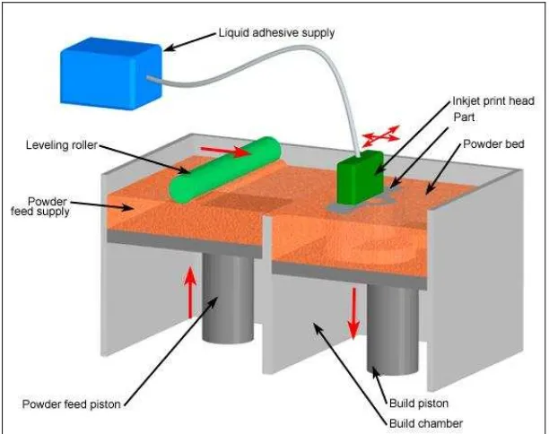
2.1.2 Three Dimensional Printing (3DP)
Three Dimensional Printing (3DP) technologies was developed at the Massachusetts Institute of Technology and licensed to several corporations. The process is similar to the Selective Laser Sintering (SLS) process, but instead of using a laser to sinter the material, an ink-jet printing head deposits a liquid adhesive that binds the material. Material options, which include ceramic powders, are somewhat limited but are inexpensive relative to other additive processes. 3D Printing offers the advantage of fast build speeds, typically two to four layers per minute. However, the accuracy, surface finish, and part strength are not quite as good as some other additive processes. 3D Printing is typically used for the rapid prototyping of conceptual models (limited functional testing is possible) (M. Firdaus, 2009).
multi-channel ink-jet print head then deposits a liquid adhesive to targeted regions of the powder bed. These regions of powder are bonded together by the adhesive and form one layer of the part. The remaining free standing powder supports the part during the build. After a layer is built, the build platform is lowered and a new layer of powder added, leveled, and the printing repeated. After the part is completed, the loose supporting powder can be brushed away and the part removed. 3D printed parts are typically infiltrated with a sealant to improve strength and surface finish (M. Firdaus, 2009).
Figure 2.1: Three dimensional printing machine system.
2.1.3 Overview the Z-Printer 310 Plus Machine
software that drives Z Corp.’s 3D printers accepts all major 3D file formats, including .stl, .wrl, .ply, and .sfx files, which leading 3D software packages can export. After exporting a solid file from a 3D modeling package, the next step is open the file in
ZPrint™, the desktop interface for Z-Printer 310 Plus. The primary function of ZPrint™
is to cut the solid object into digital cross sections or layers. In addition to sectioning the model, ZPrint™ also can utilize to address other production options, such as viewing, orienting, scaling, coloring, and labeling multiple parts. The ZPrint™ software sends 2D images of the cross sections to the 3D Printer via a standard network, just as other software sends images or documents to a standard 2D printer. Setup takes approximately 10 minutes (Z Corporation, 2005).
2.1.3.1 The Z-Printer 310 Plus Machine Operation
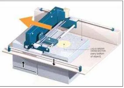
represented by 3D data. Process time depends on the height of the part or parts being built. Typically, Z-Printer 310 Plus builds at a vertical rate of 25mm –50mm (1” – 2”) per hour. When the 3D printing process completes, loose powder surrounds and supports the part in the build chamber. The part can remove from the build chamber after the materials have had time to set, and return unprinted, loose powder back to the feed platform for reuse. Then, forced air will use to blow the excess powder off the printed part, a short process which takes less than 10 minutes. The Z Corporation technology does not require the use of solid or attached supports during the printing process, and all unused material is reusable.
Figure 2.2: Spread a layer of powder