Impact of Coupled Resonator Geometry on Silicon-on
Insulator Wavelength Filter Characteristics
Hazura Haroon
a,b, Mardiana Bidin
a,b, Hanim Abdul Razak
a,b, Menon, P.S
a,
Member, IEEE,
N. ARSADa,
Member,
IEEE
and Zulatfyi F. Mohammed Napiah
ba
Institute of Microengineering and Nanoelectronics (IMEN) Universiti Kebangsaan Malaysia (UKM)
43600 UKM Bangi, Selangor, Malaysia b
Faculty of Electronics and Computer Engineering Universiti Teknikal Malaysia Melaka Hang Tuah Jaya, 76100 Durian Tunggal
Melaka, Malaysia Email: [email protected]
Abstract-We have analyzed and discussed the issues arising in
the design of Silicon - on - Insulator (SOI) wavelength filters with different types of device geometry. Microring and microdisk geometries have been chosen as the device configurations and in order to demonstrate the device performance and potential, Free Spectral Range (FSR), and Q-factor values are computed. Studies of the transmittance characteristics are carried out using Finite-Difference Time-Domain (FDTD) methods by RSOFT Software. Results show that the microring-based wavelength filter has a FSR of 1.4 THz and a Q-factor value of 486. On the other hand, the microdisk based filter has a broader FSR with slightly smaller Q-factor.
I. INTRODUCTION
Over the years, photonic circuits have been established as a promising platform for realizing densely integrated optics. To date, a variety of photonic components that emit, split, couple, guide and detect light on a chip have been demonstrated both on silicon and related materials [1-2]. Microresonators based on semiconductor waveguides are increasingly gaining attention due to wide applications such as wavelength filter, switch, sensor and modulator [3- 4]. These devices offer a numerous advantages to integrated circuits applications, such as, compactness, easy design and simpler structures. Microresonators have been utilized to develop add-drop wavelength filter with superior filter characteristics such as flat-top passband and sharp roll-off.
There are many materials have been mainly applied as a platform for resonator fabrication; polymer, GaAs/AlGaAs, Si3N4/SiO2[5-6], and so forth. However, our work has focused on SOI owing to its excellent properties such as high-index contrast, low-cost, as well as compatibility with current silicon fabrication facility [7-9].
It is known that by changing the geometrical structures or configuration of the resonator, the transmittance characteristics of the device can be altered. Thus, choosing appropriate configurations is critical to ensure an optimum resonator design to be used in very large-scale optical integrated circuits.
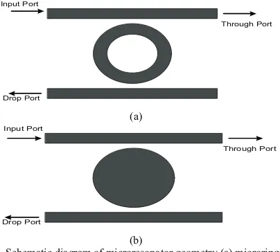
Common geometries of microresonators are spheres, disks, rings and capillaries. Here, we concentrated on microring and microdisk configuration as illustrated in Fig.1.
The purpose of this paper is to investigate the influence of the resonator geometry as one of the important feature in resonator design, where microring and microdisk configurations have been chosen for analysis, simulation and characterization.
In this paper, FDTD numerical simulations are employed to qualify key design parameters of single mode microring and microdisk based SOI filter. We have described the device designs for the filters modeling. The relationship between the device geometry and the transmission characteristics are diccussed.
II. DEVICE CONFIGURATION AND THEORY
Fig.1 shows schematically the design configurations for the proposed add-drop wavelength selective device. The devices studied in this work are designed to have a cross section of
!"#$%&'&!"#$%&()&*(+&(,&!"-!$%&./0123&('132&45620 71*8&9$%&
ring radii. The gap size between bus waveguide and circular waveguide is 300nm, the waveguide width of 400nm and ring
05311&(,&9$%"
RSM2011 Proc., 2011, Kota Kinabalu, Malaysia
Input Port Drop Port Through Port (a) Input Port Drop Port Through Port (b)
Fig.1. Schematic diagram of microresonator geometry (a) microring (b) microdisk
Theoretically, power transmission outputs at the through port and the drop port for the first order filter can be predicted by [10]:
!
"
! "
!
"
!
2 2"
2 2 2 0 2 2 2 2 2 4 4 p p o through FSR FSR T#
#
$
%
%
#
$
%
%
& ' ( ) * + , & -' ( ) * + , & -. (1)! "
!
"
!
2 2"
22 2 0 4 2 2 4 4 4 p drop FSR FSR x T
#
#
$
%
%
#
$
& ' ( ) * + , & -' ( ) * + , . (2)78202& :o1;& *82& 02;()5)*& 75<242)=*8>& ?2is the power coupling coefficient between the bus waveguide and the resonator, and
?2pis the propagation power loss coefficient per round trip in the microring resonator.
By employing the FDTD software, the input signal is applied at the input port, while the output signal will be traced either at the drop or through port; depends on the resonance
@()31*1()"&A,&*82&75<242)=*8>&:ofulfills the resonant condition,
5;& 32,1)2;& .24(7>& *82& 1)+/*& ;1=)54& 71*8& 75<242)=*8& :owill be coupled into the circular waveguide and all others will be suppressed [11].
n
effL
.
m
%
o (3)where neffis the effective index of the circular waveguide, L is the length of the ring, and m is an integer.
The frequently observed properties of optical wavelength filter are Free Spectral Range (FSR) and quality factor (Q-factor). FSR is one of the key parameters of the microresonator filters, which can be calculated by[12]:
(
2
2
)
2 2 C eff o eff o
L
R
n
L
n
FSR
&
/
.
$
%
%
(4)where R is the ring radius and LCis the coupler length. From the transmission spectrum, the FSR can be estimated by observing the difference between two consecutive resonant
peaks. Wide FSR is demanded in the integrated optics whereby more channels can be accommodated.
Another important parameter of microresonator wavelength filter is the Q-factor. In general, Q-factor can be used to predict the resonator’s ability to circulate and store input signal. The Q-factor is determined from the following equation [13]:
0 0 1 2 3 3 4 5 -& . 6 /
7
7
7
%
$
%
%
t t t L nQ gr eff
dB 2 4 1 arccos 2 2 )
( 2 2
0 3
0
(5)
where ngris the group velocity, Leffis the2,,2@*1<2&42)=*8>&B&1;& the field attenuation and tis transmission coefficient.
III. RESULTS AND DISCUSSION
To characterize the proposed optical wavelength filter, TE- light was coupled into the input port and the response at the output port was measured where the output was scanned from wavelength 1554nm to 1556nm. The device was designed to operate for TE mode of polarized light. The refractive indexes applied in the simulations were 3.47, 1.45 and 1.0 for Si, SiO2 and air, respectively. Fig.2 and Fig.3 depict the 2D simulations of light transmission for both filter topologies with the shaded bar on the right side represents linear scale of light energy.
From both figures, we can see that at the on-resonance state, most the input signal is evanescently coupled to the circular waveguide and directed to the drop port depends on the resonance frequency; where there is comparably low power at the through port. On the other hand, at the off-resonance state, the input signal bypassed the circular waveguide and emitted at the through port, and less power appeared at the drop port.
(a) (b)
Fig. 2. Light transmission in microdisk based filter (a) ON- resonance state (b) OFF-resonance state
(a) (b)
Fig. 3. Light transmission in microring based filter (a) ON- resonance state (b) OFF-resonance state
RSM2011 Proc., 2011, Kota Kinabalu, Malaysia
[image:2.595.48.289.303.418.2]0 0.1 0.2 0.3 0.4 0.5 0.6 0.7 0.8 0.9 1
1540 1545 1550 1555 1560
Through Drop
(a)
0 0.2 0.4 0.6 0.8 1 1.2
1540 1545 1550 1555 1560
Through Drop
(b)
Fig. 4. Output response of (a) microring based filter (b) microdisk based filter
The resultant transmission response at the through and drop port for both designs with the same radius of curvature are presented as in Fig. 4. In Fig.4 (a), the filter was resonated at wavelength 1544nm and 1556 giving the FSR of 11nm or 1.4 Thz. The FSR value obtained is sufficient for a filtering applications, as it represents the spectral bandwidth of the system to be utilised. At 1544nm resonance wavelength, the Q-factor value calculated is 486.
The same trend is observed in case of microresonator with a microdisk geometry, as depicted in Fig. 4(b). We note that the microdisk geometry contributes less output power at the drop channel. This is due to weaker mode confinement in the disk structure, as compared to ring structure. This phenomenon is called substrate leakage loss, thus leads to signal attenuation. As seen from the figure, the locations of the two highest resonances have changed to 1548nm and 1560nm, with FSR = 12nm (1.5 THz) and Q-factor of 447. Obviously, in comparing the two structures, the microdisk based filter has a wider FSR, nonetheless the Q-factor is lesser. In addition, the transmission loss is 28% higher than the microring structure.
IV. CONCLUSIONS
We have presented that the microresonators geometries have significant effects on the wavelength filter performance. The performance of the device via simulation can be improved if we prolonged the computation time. This work will continue with fabrication and characterization. For this purpose, the results provide here will be useful guidance before laboratory works are carried out.
ACKNOWLEDGMENT
The authors would like to thank Universiti Teknikal Malaysia Melaka (UTeM) for the support. This research is supported by funding from Universiti Kebangsaan Malaysia, grant no: UKM-OUP-NBT-27-119/2011 and Industri-2011-015. The authors would also like to acknowledge Ministry of Higher Education, Malaysia for their support.
REFERENCES
[1] P. S. Menon, K. Kandiah, A. A. Ehsan and, S. Shaari, “The development of a new responsivity prediction model for In(0.53)Ga(0.47)As interdigitated lateral PIN photodiode,” Journal of Optical Communications, vol. 30, no. 1, pp. 2-6, 2009.
[2] Menon, P. S., Kandiah, K., Ehsan, A.A and Shaari, S, “An interdigitated diffusion-based In(0.53)Ga(0.47)As lateral PIN photodiode,”
Proceedings of SPIE - The International Society for Optical Engineering, 6838, art. no. 68380, 2008.
[3] F. Xia, L. Sekaric and Y. Vlasov, "Ultracompact optical buffers on a silicon chip", Nature Photonics, vol. 1, pp. 65-71, 2007
[4] W. Y. Deng, D. G. Sun, S. L.E., and W. Xu, " Analysis od a 1x32 polymer microring resonant wavelength de-multi/multiplexer assistant with interleave filter",Optik, vol. 120, pp. 188-194 , 2009.
[5] C.YChao, W. Fung, and L.J Guo, "Polymer microring resonators for biochemical sensing applications,"Optics Express, vol.18, no. 2, pp. 393-400, 2010.
[6] P.P.Absil. J.V. Hryniewicz, B.E. Little, P.S. Cho, R.A. Wilson, L.G. Joneckis, and P.-T. Ho, “Wavelength conversion in GaAs micro-ring resonators,” Optics Letters, vol. 25, no. 8, pp. 554-556, April 2000. [7] Hazura H., Hanim A.R., Mardiana B., Sahbudin Shaari, and Menon P.S,
"Free carrier absorption loss of p-i-n silicon- on- insulator (SOI) phase modulator” in International Conference on Enabling Science and Nanotechnology (Escinano) 2010 Proceedings, Malaysia, 2010.
[8] Sahbudin Shaari, Hanim A.R, Mardiana B., Hazura H., Menon, P.S, "Modeling and analysis of lateral doping region translation variation on optical modulator performance" inthe 4thAsian Physics Symposium AIP Conference Proceedings,vol. 1325, pp.297-300, 2010.
[9] Hazura H., Hanim A.R., Mardiana B., Menon P.S., "An analysis of silicon waveguide phase modulation efficiency based on carrier depletion effect" in IEEE International Conference on Semiconductor Electronics 2010 (ICSE '10) , pp. 348-350, Malaysia, 2010.
[10] S. Xioa, M. H. Khan, H. Shen, and M. Qi, “Modeling and measurement of losses in silicon-on- insulator resonators and bends,” Optics Express, vol. 15, no. 17, pp. 10553-10561, 2007.
[11] C.-Y. Chao, and L.J. Guo, “Design and optimization of microring resonators in biochemical sensing applications,: J. Lightwave Technol., vol. 24, no. 3, pp. 1395-1402, March 2006.
[12] http://www.apollophoton.com/apollo/APNT/APN-APSS-RingResonator.pdf
[13] A. Vorckel, M. Monster, W. Henschel, P. H. Bolivar, and H.Kurz, “ Asymetrical coupled silicon-on-insulator microring resonators for compact add-drop multiplexers,” Photon. Technol. Letter., Vol. 15, pp. 921-923, 2003.
RSM2011 Proc., 2011, Kota Kinabalu, Malaysia