Australian Journal of Basic and Applied Sciences
Journal home page: www.ajbasweb.com
Corresponding Author: Zahriladha Zakaria, Centre for Telecommunication Research and Innovation (CeTRI), Faculty of Electronics and Computer Engineering, Universiti Teknikal Malaysia Melaka (UTeM), Hang Tuah Jaya 76100 Durian Tunggal, Melaka, Malaysia.
Centre of Telecommunication Research and Innovation (CeTRI), Department of Telecommunication Engineering, Universiti Teknikal Malaysia Melaka (UTeM), Hang Tuah Jaya 76100, Melaka, Malaysia
A R T I C L E I N F O A B S T R A C T
This paper presents the investigation and characterization of dual-mode Substrate Integrated Waveguide (SIW) filter with two metalized posts on the cavity to reduce the overall volume of RF front-end subsystems. By introducing two vertical metalized posts and two diagonal metalized posts in dual-mode SIW filter, both SIW filters show different flow of Electromagnetics (EM) can be identify from the E-fields. In order to compare which dual-mode SIW filter gives the better performance, the designs are simulated at centre frequency 2 GHz using CST Studio Suite software and the results are validate through measurement. The measurement shows a good agreement with the simulated results. This design is suitable for any integration microwave system where the reduced complexity of the design and cost as well as weight is very important for the wireless communication systems.
© 2013 AENSI Publisher All rights reserved. INTRODUCTION
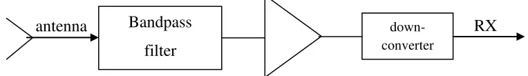
Most of the applications are diverse although satellite television as well as in to public and military radar systems in wireless communication systems. In most communication systems the receiving antenna is accompanied by a bandpass filter shown in Figure 1. In the microwave band, normally the receiving bandpass filters are distributed. These bandpass filters are not compact and in most applications their size becomes a subject and as such may not provide a better solution.
Fig. 1: Typical block diagram of receiving front end of communication system
Most of the researchers have taken this issue into account to invent an alternative solution for the better communication systems that able to reduce the overall volume, manufacturing time and manufacturing cost. However, most of the wireless communication applications required the better performance in term of selectivity, simple, small in size and easy to fabricate of the filter that can be implemented in systems (Zhang, Y.L., et. al., 2005; Potelon, B., et. al., 2006; Wu, L.S., et. al., 2009; Athanasopoulos, N.C., et. al., 2011; Bozzi, M., et. al., 2011). Basically, filters are one of most important part that used to filter unwanted signal from the receiving signal from the antennas. In order to get better performance, filters need to design based on a good selectivity to avoid any important information or signal is filtering out from the filters.
filter. The method applied for dual-mode SIW filter in Deslandes, D. and K. Wu, 2003 by adjusting the position of the probes in order to get better performance. However, the design structure looks not symmetric and the selectivity is not good which is increasing the bandwidth. In Chuang, C.C., et. al., 2007 and Wang, D.P., et. al., 2008, the dual-mode SIW filter was design with additional perturbation vias was used on the filter design. However, the selectivity of the filter design is not narrow enough will affect the overall insertion loss response. Meanwhile in Li, R.Q., et. al. 2010, the design is using slot lines perturbation method to produce dual-mode response. However, the measurement for insertion loss is slightly poor than the simulated design.
In this paper, a development of dual-mode SIW filter based on microwave filter circuit theory is presented. The dual-mode SIW filter is designed at resonant frequency of 2 GHz based on 2 type’s position of the metalized posts i.e. vertical and diagonal. The advantages of this method are to realize the SIW filter that can be transformed for broadband applications and also can be applied to the any integration systems between microwave filter and any planar structures.
The physical layout dual-mode SIW filter using metalized posts is presented. Resonant frequency of 2 GHz is selected as the centre frequency to proof the concept for this technique. TE102 is used as a dominant mode to realize a dual-mode of the microwave filter as a mode of propagation. The scope of work in this paper will focuses on metalized posts method of SIW filter design.
Resonant Circuit Of Dual-Mode Siw Filter:
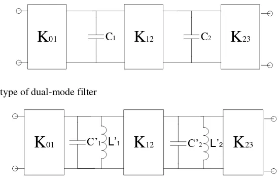
In this section, a low-pass prototype equivalent circuit is used to produce dual-mode SIW filter equivalent circuit as shown in Figure 2. The impedance inverter, K01, K12 and K23 represents the coupling method between the input port and the output of the filter. In Figure 3 shows the equivalent circuit of dual-mode based on the low-pass prototype circuit. It can be developed based on the combination of two single-mode equivalent circuit into one Abunjaileh, A.I., et. al., 2007. The most important about designing the dual-mode equivalent circuit of SIW filter and is used to produce a better selectivity of response. This design also can used to integrate with any applicable equivalent circuit of filter with suitable common impedance matching.
K
12K
01 C1 C2K
23Fig. 2: Low-pass prototype of dual-mode filter
K
12K
01 C’1 L’1 C’2 L’2K
23Fig. 3: Equivalent circuit of dual-mode bandpass filter
The capacitance Cr and the impedance inverter Kr, r+1 value of the low-pass prototype can be determined using the following equation (Hunter, I.C., 2001; Zakaria, Z., et. al., 2013):
� =2
�sin
2 −1 �
2� (1)
, +1=
�2+� 2 �/� 1/2
� (2)
where the number of orders, N of the network andη is defined as (Hunter, I.C., 2001; Zakaria, Z., et. al., 2013):
�= � ℎ 1
� � ℎ−1
1
while � is the ripple of insertion loss. The transformation of the low-pass prototype equivalent circuit into bandpass equivalent circuit can be determined using the following equation (Hunter, I.C., 2001; Zakaria, Z., et. al., 2013):
′ = 1
�� � (4)
�′ =��
�0 (5)
where � is the geometric midband frequency; �′ is capacitance; ′ is inductive; � is the bandwidth scaling factor and the r is representative as number of orders.
Design Of Dual-Mode Siw Filter Cavity:
Substrate Integrated Waveguide (SIW) filter is the most recent interest of many researchers due to its various benefits in microwave filter technology. The SIW has the advantages in term of high power handling capability, low losses, low weight, low cost and planar compatibility Grubinger, H., et. al., 2009; Liu, J., et. al., 2011, but they also present overall design flexibility. The structure of SIW is an artificial waveguide which is constructed on a planar substrate with periodic arrays of metalized via holes. The effects on the array of via holes act as a boundary that prevents the escaping of the electric field (E-field); thus providing an artificial wall constructed with similar properties to rectangular waveguide (Zakaria, Z., et. al., 2012). The rule of the design for the rectangular SIW based upon � is determined by the resonant frequency (Chuang, C.C., et. al., 2007; Wang, Y., et. al., 2010; Zakaria, Z., et. al., 2008; Zakaria, Z. and B.H. Ahmad, 2011):
( )=2� � � 2
+ � 2+ �
2
(6)
where , and are the mode of indexes for � mode; is the free-space velocity of light; while the efficient length, , and efficient width, are dimensions of the SIW cavity.
′= ��−
2
0.95 , ′= ��− 2
0.95 (7)
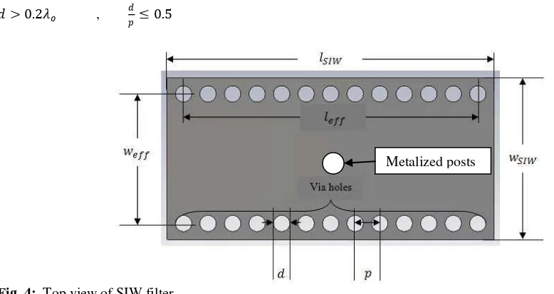
where, ��and ��are the length and width of the resonant SIW cavity, d and p are the diameter and the distance between adjacent vias respectively. and � are the relative permeability and the dielectric constant of the substrate respectively. The metalized via holes diameter, d and pitch, p can be calculated using the design rules from the following equations (Wu, K., et. al., 2003) as shown in Figure 4.
> 0.2 , ≤0.5 (8)
Fig. 4: Top view of SIW filter
RESULTS AND DISCUSSION
The dual-mode SIW filter equivalent circuit has been designed at centre frequency of 2 GHz by using equations (1) – (5) to obtain the coupling value, K01 = K23 = 50 and K12 = 69.37, capacitance, C’1 = C’2 =
108.2313 pF and inductance, L’1 = L’2 = 58.5075 pH. The simulated result of the dual-mode SIW filter equivalent circuit is shown in Figure 5. The return loss, S11, with better than -10 dB, insertion loss, S21 of 0 dB with a bandwidth of around 40 MHz have been achieved.
The physical layout design of the dual-mode SIW filter is then simulated using CST Microwave Studio software. The devices are constructed using FR-4 material on a 1.6 mm dielectric substrate thick with dielectric constant � = 4.6. The copper thickness is 0.035 mm and the loss tangent is 0.019. The dimensions of dual-mode SIW can be calculated using equations (6) – (8).
Fig. 5: Simulation results of equivalent circuit SIW filter
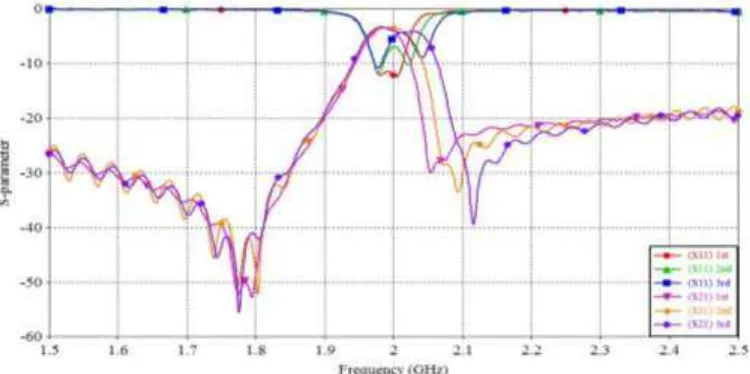
It is found that the diagonal gap between two centre metalized posts is considered and needs to be optimized in order to achieve a better response. Figure 6 shows the variation of the gap of the SIW resonator, indicating the increase or decrease in the gap that will shift the resonator frequency to a lower or higher frequency. In this analysis, at resonance of 1.990 GHz when the gap between two centre metalized posts is 84.86 mm (1st), at a resonance of 2.001 GHz, the gap increase to 85.86 mm (2nd) and at a resonance of 2.012 GHz, the gap increase to 86.86 mm (3rd). As the gap increases, the resonant frequency increase as well as the value of return loss (S11) decreases too. However, there is a major shift of insertion loss (S21) to a higher frequency when the variation of the gap of the SIW resonant increases.
Fig. 6: Effect of gap between two metalized posts
Meanwhile for the vertical gap between two centre metalized posts is considered and needs to be optimized in order to achieve a better response. Figure 7 shows the variation of the vertical gap of the SIW resonator, indicating the increase or decrease in the gap that will shift the resonator frequency to a lower or higher frequency. In this analysis, at resonance of 2 GHz when the gap between two centre metalized posts is 7.5 mm (1st), at a resonance of 2.004 GHz, the gap increase to 8 mm (2nd) and at a resonance of 2.014 GHz, the gap increase to 8.5 mm (3rd). As the gap increases, the resonant frequency as well as the value of return loss (S11) increases too. However, there is a minor shift of insertion loss (S21) to a higher frequency when the variation of the gap of the SIW resonant increases.
2.0
1.6 2.4
-30 -20 -10
-40 0
Frequency (GHz)
S
-p
ara
m
et
er
(d
Fig. 7: Effect of gap between two metalized posts
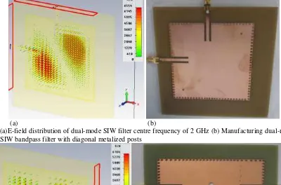
The Electric field (E-field) for the TE102 of the dual-mode SIW filter with diagonal metalized posts is simulated at centre frequency of 2 GHz is shown in Figure 8(a) The simulations show the magnitude of E-field is typically concentrated at diagonal positions of dual SIW cavity with diagonal metalized posts. The physical layout of the dual-mode SIW resonator filter with vertical metalized posts from the manufacturing fabrication is shown in Figure 8(b). Meanwhile, the Electric field (E-field) for the TE102 mode of the dual-mode SIW filter with vertical metalized posts at centre frequency of 2 GHz is shown in Figure 9(a). The simulations show the magnitude of E-field is typically concentrated at 2 positions horizontally of dual SIW cavity with vertical metalized posts. The physical layout of the dual-mode SIW resonator filter with vertical metalized posts from the manufacturing fabrication is shown in Figure 9(b).
(a) (b)
Fig. 8: (a)E-field distribution of dual-mode SIW filter centre frequency of 2 GHz (b) Manufacturing dual-mode SIW bandpass filter with diagonal metalized posts
(a) (b)
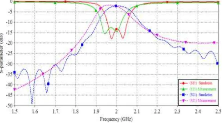
Meanwhile, Figure 10 shows the simulated and measured results on the dual-mode SIW filter with diagonal metalized posts. The physical length, �� and width, �� of SIW filter are 118 mm and 118 mm, metalized post diameter = 1 mm, whilst the via-hole diameter, d = 2 mm and the pitch, p = 3 mm respectively. The simulated results show that the return loss (S11) is better than -11 dB and insertion loss (S21) of -3.4 dB with a bandwidth of around 56 MHz at frequency 1.99 GHz. In the experimental results, the centre frequency of 2.095 GHz with a return loss (S11) and insertion loss (S21) of -12 dB and -6.5 dB and bandwidth of around 60 MHz are measured. However, there is nevertheless a noted frequency shift to the left of 96 MHz (4.82%) from the centre frequency.
Fig. 10: Comparison of simulated and measured response
Figure 11 shows the simulated and measured results on the dual-mode SIW filter with vertical metalized posts. The physical length, �� and width, �� of SIW filter are 120 mm and 91 mm, metalized post diameter = 3.88 mm, whilst the via-hole diameter, d = 2 mm and the pitch, p = 3 mm respectively. The simulated results show that the return loss (S11) is better than -15 dB and insertion loss (S21) of -2.2 dB with a bandwidth of around 74.4 MHz. In the experimental results, the centre frequency of 1.975 GHz with a return loss (S11) and insertion loss (S21) of -12.6 dB and -2 dB and bandwidth of around 87.6 MHz are measured. However, there is nevertheless a noted frequency shift to the left of 25 MHz (1.25%) from the centre frequency which is due to the variations of permittivity in the substrate, i.e. 4.6 ± 0.15 (≈ up to 3.26%) and the inconsistencies of dielectric thickness, i.e. 1.6 ± 0.025 (≈ up to 1.56%) , and also manufacturing tolerance. The losses which occurred, particularly in the passband are due to the losses at the transitions from microstrip to SIW and also through SMA connectors. In addition, radiation loss through the surface of the SIW cavity, and leakage through via-holes and pitches, also contributes a small amount of loss.
Fig. 11: Comparison of simulated and measured response
of return loss, insertion loss and the frequency shift. However, dual-mode SIW filter with diagonal metalizes posts has better bandwidth than vertical metalized posts. In summary results, dual-mode SIW filter with vertical metalized has better overall results that can give better performance which in line with the simulated and measured results with smaller size compare with the dual-mode SIW filter with diagonal metalized posts.
Table 1: Summary comparison simulated with measurement results Frequency agreement with the ideal circuit. The experimental results of the dual-mode SIW filter show a good agreement and in-line with the simulated performance. This method would be useful in integrating with any planar structure as well as the overall physical volume.
ACKNOWLEDGEMENT
W. Y. Sam would like to thank UTeM and the MyBrain15 program for sponsoring this study. The authors would also like to thank UTeM for sponsoring this work under the short-term grant UTeM PJP/2012/FKEKK(15B)/S01019 and RAGS/2012/FKEKK/TK02/1 B00004.
REFERENCES
Abunjaileh, A.I., I.C. Hunter and A.H. Kemp, 2007. Application of Dual-mode Filter Techniques to the Broadband Matching of Microstrip Patch Antennas. Microwaves, Antennas & Propagation, IET, 1(2): 273-276.
Athanasopoulos, N.C., D.V. Makris and K.N. Voudouris, 2011. 5th Order Militmeter-wave Substrate Integrated Waveguide Band Pass Filters. International Conference on Electromagnetics in Advanced Applications (ICEAA), IEEE, pp: 98-101.
Bozzi, M., A. Georgiadis and K. Wu, 2011. Review of Substrate-Integrated Waveguide Circuits and Antennas. Microwaves, Antennas & Propagation IET, 5(8): 909-920.
Chuang, C.C., H.H. Lin and C.L. Wang, 2007. Design of Dual-Mode SIW Cavity Filters. TENCON, Region 10 Conference, IEEE, pp: 1-4.
Deslandes, D., and K. Wu, 2003. Millimeter-wave Substrate Integrated Waveguide Filters. Canadian Conference on Electrical and Computer Engineering (CCECE), IEEE, pp:1917-1920.
Grubinger, H., H. Barth and R. Vahldieck, 2009. An LTCC-based 35 GHz Substrate-Integrated-Waveguide Bandpass Filter. MTT-S International Microwave Symposium Digest (MTT), pp:1605-1608.
Hunter, I.C., 2001. Theory and Design of Microwave Filter, London: Institution of Electrical Engineers. Li, R.Q., X.H. Tang and F. Xiao, 2010. Substrate Integrated Waveguide Dual-mode Filter using Slot Lines Perturbation. Electronic Letters, 46(12): 223-224.
Liu, J., D.R. Jackson and Y. Long, 2012. Substrate Integrated Waveguide (SIW) Leaky-Wave Antenna With Transverse Slots. IEEE Transaction on Antenna and Propagation, 60(1): 20-29.
Mostrah, A.E., B. Potelon, E. Rius, C. Quendo, J.F. Favennec, H. Leblond, H. Yahi and J.L. Cazaux, 2010. C-Band Inductive Post SIW Alumina Filter for a Space Application. Expreimental Analysis of the Thermal Behaviour, Proceeding of Asia-Pacific Microwave Conference Proceeding (APMC), pp:103-106.
Potelon, B., J.C. Bohorque, J.F. Favennec, C. Quendo, E. Ruis and C. Person, 2006. Design of Ku-Band Filter based on Substrate Integrated Circular Cavities (SICCs). MTT-S International Microwave Symposium Digest (MTT), pp: 1237-1240.
Wang, D.P., W.Q. Che and P. Russer, 2008. Tunable Substrate-Integrated Waveguide (SIW) dual-Mode Square Cavity Filter with Metal Cylinders. MTT-S International Microwave Workshop Series on Art of Miniaturizing RF and Microwave Passive Components, IEEE, pp: 128-131.
Wu, K., D. Deslandes and Y. Cassivi, 2003. The Substrate Integrated Circuits – A New Concept for High-Frequency Electronics and Optoelectronics. 6th International Conference on Telecommunications in Modern Satellite, Cable and Broadcasting Service, pp: 3-10.
Wu, L.S., L. Zhou, X.L. Zhou and W.Y. Yin, 2009. Bandpass Filter Using Substrate Integrated Waveguide Cavity Loaded With Dielectric Rod. Microwave and Wireless Components Letters, IEEE, 19(8): 491-493.
Zakaria, Z., B.H. Ahmad, 2011. Design of SIW Bandpass Filter with 6 dB Offset. International RF Microwave Conference (RFM), IEEE, pp: 87-90.
Zakaria, Z., I.C. Hunter and A.C. Guyette, 2008. Design of Coaxial Resonator with Nonuniform Dissipation. MTT-S International Microwave Symposium Digest, IEEE, pp: 623-626.
Zakaria, Z., W.Y. Sam, M.Z.A. Abd Aziz, A.A.M. Isa and F.M. Johar, 2012. Design of Integrated Rectangular SIW Filter and Microstrip Patch Antenna. Asia-Pacific Conference on Applied Electromagnetics (APACE), pp: 137-141.
Zakaria, Z., W.Y. Sam, M.Z.A. Abd Aziz, K. Jusoff M.A. Othman, B.H. Ahmad, M.A Mutalib and S. Suhaimi, 2013. Hybrid Topology of Substrate Integrated Waveguide (SIW) Filter and Microstrip Patch Antenna for Wireless Communication System. Australian Journal of Basic and Applied Sciences, 7(3): 24-34.
Zakaria, Z., W.Y. Sam, M.Z.A. Abd Aziz, M. Muzafar Ismail, 2013. The Integration of Rectangular SIW Filter and Microstrip Patch Antenna based on Cascaded Approach, Procedia Engineering, Elsevier, 53(1): 347-353.
Zakaria, Z., W.Y. Sam, M.Z.A. Abd Aziz and M.A. Meor Said, 2012. Microwave Filter and Antenna for Wireless Communication Systems. Symposium on Wireless Technology and Application (ISWTA), IEEE, pp: 220-223.
Zakaria, Z., W.Y. Sam, M.Z.A. Abd Aziz and M.A. Meor Said, 2012. Rectangular Microstrip Patch Antenna Based on Resonant Circuit Approach. Symposium on Wireless Technology and Application (ISWTA), IEEE, pp: 220-223.