i
ANALYSIS AND DEVELOPMENT OF MULTIPLE-BAND BANDSTOP FILTER
USING SUBSTRATE INTEGRATED WAVEGUIDE (SIW) TECHNOLOGY
ZAHARULRIZAL BIN ZAKARIA
This Report Is Submitted In Partial Fulfillment Of Requirements For The Bachelor
Degree of Electronic Engineering (Industrial Electronic) With Honors
Faculty of Electronic and Computer Engineering
Universiti Teknikal Malaysia Melaka
ii
UNIVERSTI TEKNIKAL M ALAYSIA M ELAKA
FAKULTI KEJURUTERAAN ELEKTRONIK DAN KEJURUTERAAN KOM PUTER
BORANG PENGESAHAN STATUS LAPORAN
PROJEK SARJANA M UDA II
Tajuk Projek :
ANALYSIS AND DEVELOPMENT OF MULTIPLE-BAND BANDSTOP FILTER USING SUBSTRATE INTEGRATED WAVEGUIDE (SIW) TECHNOLOGY
Sesi Pengajian : 2010/ 2011
Saya ZAHARULRIZAL BIN ZAKARIA m engaku m em benarkan Laporan Projek Sarjana M uda ini disimpan di Perpust akaan dengan syarat -syarat kegunaan sepert i berikut :
1. Laporan adalah hakmilik Universiti Teknikal M alaysia M elaka.
2. Perpust akaan dibenarkan m em buat salinan unt uk t ujuan pengajian sahaja.
3. Perpust akaan dibenarkan m em buat salinan laporan ini sebagai bahan pert ukaran ant ara inst it usi
pengajian tinggi.
4. Sila t andakan ( √ ) :
SULIT*
* (M engandungi maklumat yang berdarjah keselamat an atau kepent ingan M alaysia sepert i yang t ermaktub di dalam AKTA
RAHSIA RASM I 1972)
TERHAD* * * * (M engandungi maklumat t erhad yang t elah dit ent ukan oleh organisasi/ badan di mana penyelidikan dijalankan)
TIDAK TERHAD
Disahkan oleh:
__________________________ ___________________________________
iii
“I declare that this report is all my own work except the certain passage that I have
clarified each of their sources.”
Signature : ………
Prepared by : ZAHARULRIZAL BIN ZAKARIA
iv
“I declare that I have read this report and in my opinion I think this report is sufficed in
partial fulfillment of requirements for the Bachelor of Electronic Engineering with
Honors (Electronic Industry).”
Signature : ………
Supervised by: PM. TAN KIM SEE
v
Special dedication to my family, my kind hearted supervisor PM. Tan Kim See and to all
vi
ACKNOWLEDGEMENT
In the name of Allah, the most Gracious and Merciful, whom without His loving
and Blessing, I would not be able to finish my Projek Sarjana Muda and do this report
on time.
I would like to extend my sincere gratitude to my supervisor, PM Tan Kim See,
for his assistance and guidance towards the progress of this thesis project. Throughout
the year, PM. Tan has been patiently monitoring my progress and guided me in the right
direction and offering encouragement. Obviously the progress I had now will be
uncertain without his assistance.
My special appreciation and thanks to all my friends who were involve directly
or indirectly for their invaluable assistance towards this project thesis. I would like to
thank to Universiti Teknikal Melaka Melaysia (UTeM), my faculty lecturer, lab
technician for the support and guidance that had encouraged me to finish this project.
Lastly, the most of all I am very grateful to my family for their unfailing encouragement
vii
ABSTRACT
This project is about the analysis and development of a multiple-band bandstop
filter using Substrate Integrated Waveguide (SIW) technology. Bandstop and bandpass
filters play an important role in microwave and millimeter-wave systems, which are
applied to discriminate the desired and unwanted signals. A new transversal coupling
network is used to design a multiple-band bandstop filter. By carefully placing
resonators in the coupling network will result in the generation of a number of centre
frequencies. Some of these frequencies may have similar resonating frequency to realize
a number of frequency band rejections or suppressions which can be applied to reject
pulse signals or bandwidth signals in broadband application. This filter will be use in
X-band which is for military broadX-band microwave application. This project will study and
analyze on the feasibility of the number of the band suppressions or rejections and
develop a prototype for best application. Whilst many researches using Substrate
Integrated Waveguide (SIW) technology are being carried out because of it has proven
its significance in microwave and millimeter-wave communication systems for its
attractive advantages of high Q, low insertion, reduced size, low costs, and easily to be
viii
ABSTRAK
Projek ini adalah berkenaan dengan analisis dan menghasilkan multi-band
bandstop filter menggunakan teknologi Substrat Integrated Waveguide (SIW). Bandstop
dan bandpass filter memainkan peranan penting untuk membezakan isyarat yang
diingini dan tidak diingini dalam microwave dan sistem milimeter-wave. Konsep new
transversal coupling network telah digunakan untuk menghasilkan multi-band bandstop
filter. Dengan memasukkan resonator ke dalam coupling network akan menghasilkan
beberapa jumlah generasi frequecy centre. Beberapa frekuensi mungkin mempunyai
frekuensi resonansinya sama untuk mewujudkan sejumlah frequency band yang tidak
diingini atau hendak di hentikan yang boleh dilaksanakan untuk menolak isyarat pulse
atau isyarat bandwidth dalam aplikasi broadband. Filter ini akan digunakan di X-band
sebagai aplikasi tentera dalam microwave broadband. Projek ini akan mengkaji dan
menganalisis mengenai seberapa banyak jumlah suppresion band atau rejection band
yang boleh dimasukkan ke dalam satu filter dan menghasilkan prototaip untuk aplikasi
terbaik. Sementara itu, banyak kajian telah dibuat dengan menggunakan teknologi
Substrat Integrated Waveguide (SIW) sedang dilakukan kerana mempunyai banyak
kebaikan yang telah terbukti signifikan dalam komunikasi microwave dan sistem
milimeter-wave seperti berkualiti tinggi, penyisipan rendah, mengurangkan saiz, kos
rendah, dan mudah untuk diintegrasikan dengan litar planar yang dari waveguide persegi
ix
CONTENT
CHAPTER ITEM PAGE
PROJECT TITLE i
PSM STATUS VERIFICATION FORM ii
DECLARATION iii
SUPERVISOR VERIFACATION iv
DEDICATION v
ACKNOWLEDGEMENT vi
ABSTRACT vii
ABSTRAK viii
CONTENT ix
LIST OF TABLE xii
LIST OF FIGURE xiii
LIST OF ABREVIATION xv
1 INTRODUCTION
1.1 INTRODUCTION 1
1.2 PROJECT OBJECTIVE 3
1.3 PROJECT SCOPE 4
1.4 PPROBLEM STATEMENT 5
x
2 LITERATURE REVIEW
2.1 INTRODUCTION 7
2.2 APPLICATION OF RF AND MICROWAVE
FILTER
9
2.3 NEW TRANSVERSAL COUPLING NETWORK 10
2.4 TE MODES 12
2.5 SUBSTRATE INTEGRATED WAVEGUIDE
(SIW)
14
2.6 VIAS HOLE 17
2.7 TRANSITION BETWEEN PLANAR CIRCUIT
AND SIW
18
2.8 OPERATION FREQUENCY 19
2.8.1 Satellite communications 19
2.8.2 Radar 19
2.8.3 Terrestrial communications and networking 19
2.8.4 Amateur radio 20
3 PROJECT METHODOLOGY
3.1 PROCESS OUTLINE 21
3.2 FLOW CHART 24
3.3 K-CHART 25
3.4 GANTT CHART 26
3.5 SIMULATION DESIGN 27
3.6 ETCHING PROCESS 32
3.6.1 Exposing and developing the resist layer 33
3.6.2 Etching the printed circuit board 34
3.6.3 Drilling, shaping and soldering the board 36
xi
4 PROJECT THEORY AND CALCULATION
4.1 INTRODUCTION 40
4.2 FILTER SPECIFICATION 41
4.3 THEORITICAL AND CALCULATION 43
4.3.1 Transmission line 43
4.3.2 Vias hole 44
4.3.3 The resonator 45
4.3.4 Step Impedance 46
5 RESULT AND ANALYSIS
5.1 INTRODUCTION 48
5.2 MULTIPLE-BAND BANDSTOP FILTER 49
5.3 RESULT 52
5.4 RESULT ANALYSIS 54
6 CONCLUSION AND SUGGESTION
6.1 CONCLUSION 57
6.2 DISCUSSION 59
6.3 SUGGESTION 60
6.4 REFERENCES 61
APPENDIX A: POSTER 62
xii
LIST OF TABLE
NO TITLE PAGE
4.1 Board Specification 41
4.2 Band specification 42
xiii
LIST OF FIGURE
NO TITLE PAGE
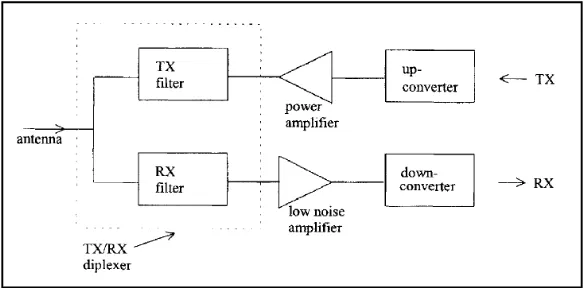
2.1 RF front end of a cellular base station 9
2.2 The transversal coupling network 10
2.3 Filter coupling schemes 11
2.4 Electrical and magnetic fields for the TE10 mode in a rectangular
waveguide.
13
2.5 The geometric parameters for via diameter, via spacing, waveguide
physical width, and substrate height as: d, s, w, and h.
14
2.6 The effects of arrays of via holes which act as boundary to prevent
the electrics field from escaping thus provide an artificial wall
similar to waveguide.
16
2.7 Diameter and pitch 17
3.1 Draw of design 27
3.2 Unit Setup 28
3.3 Material Setup 29
3.4 Wave port setup 29
3.5 Solution setup 30
3.6 Result Setup 31
3.7 PCB layout for Exposure Process 33
xiv
4.1 The vias hole 45
4.2 The resonator 46
4.3 Transition between microstrip line and SIW 47
5.1 Filter Design 49
5.2 Filter prototype 50
5.3 Simulation result 52
5.4 Measurement result 53
xv
LIST OF ABBREVIATION
3D 3 Dimension
DBS Direct Broadcast Satellite
EBG Electromagnetic Band Gap
GHz Giga Hertz
GPS Global Positioning Satellite
HFSS High Frequency Structures Simulation
IEEE Institute of Electrical and Electronics Engineers
ITU International Telecommunications Union
MHz Mega Hertz
mm Millimeter
PCB Printed Circuit Board
PCS Personal Communication Systems
RF Radio Frequency
SIW Substrate Integrated Waveguide
SMA Sub-Miniature version A
TE Transverse Electric
TEM Transverse Electric and Magnetic
TM Transverse Magnetic
TV LNB Television Low Noise Block-downconverter
2
CHAPTER I
INTRODUCTION
1.1 INTRODUCTION
Microwave filter can be found in most of microwave subsystems, from
entertainment via satellite television, to civil and military radar systems. The increasing
development of microwave and millimeter-wave communication systems has promoted
the need for suppression of multiple unwanted signals for military broadband
applications [1]. Bandstop and bandpass filters play an important role in microwave and
millimeter-wave systems, which are applied to discriminate the desired and unwanted
signals. Many bandstop filters are mainly designed for single-band rejection
applications.
This project is about the development of a multiple-band bandstop filter which is
the single filter that consists of more than two stop band frequencies. In order to achieve
this project, a new transversal network is used in the rectangular waveguide to design a
multiple-band bandstop filter by combining several resonators to the transmission line.
This project will study and analyze on the feasibility of the number of the band
suppressions or rejections which can be applied to reject pulse signals or bandwidth
3
This filter will operate in the X-band network because this network consist of the
operation of communication that related to the military, such as satellite communication,
radar, space communication, amateur radio and terrestrial communications and
networking. SIW technology will be used in this filter because of it has proven its
significance in microwave and millimeter-wave communication systems for its attractive
advantages of high Q, low insertion, reduced size, low costs, and easily to be integrated
4
1.2 PROJECT OBJECTIVE
The objective of this project is to analyze and develop a multiple-band bandstop
filter by using Substrate Integrated Waveguide (SIW) technology. This objective can be
achieved by understanding the concepts of new transversal network in rectangular
waveguide in order to design multiple-band of bandstop filter. The increasing
development of microwave and millimeter-wave communication systems has promoted
the need for suppression of multiple unwanted signals for military broadband
applications. Bandstop and bandpass filters play an important role in microwave and
millimeter-wave systems, which are applied to discriminate the desired and unwanted
signals.
Many bandstop filters are mainly designed for single-band rejection applications.
The new transversal network which uses a resonator concept can combine the
single-band rejection to be two or multiple-single-band rejection. Besides, the technology of filter is
also very important on this project. There are a lot of types of rectangular waveguide
that can be used but this project will use SIW technology. SIW is new technology of the
filter that promise many more advantages. To apply this technology to the multiple-band
bandstop filter, the concept of SIW has to be understood first. The SIW replacing the
waveguide walls with a series of metallic via holes through the substrate to achieve the
same effect of metallic walls.
Furthermore, the type of board is also an important consideration in this project.
The board will give different result from fabricated and simulated results. To minimize
the difference between the simulation and fabrication, suitable board has to be chosen.
An in-depth understanding and familiarization on the simulation software is required
before the prototype can be considered. This SIW technology is a new technology, so
ADS software will come handy for the simulation process. This project will used HFSS
5
1.3 PROJECT SCOPE
The scope of work of this project is to study and analyze the data or information
about two major areas of interest. The first one is to understand the concept and
principal of the multiple-bandstop filter and the second is the SIW technology in order to
achieve the objective of this project. The main scope of this project is to fully understand
the principles of filters by studying the characteristics of the bandstop filter and collect
the data and information on this topic. For the multiple-band bandstop filter, it will be
focused on the understanding and analysis of the concept and properties of the new
transversal network and the feasibility of the number of the band suppressions or
rejections. Then outcome is to develop a prototype for best application as published in
numerous papers and books.
With the SIW technology, time was set aside to study, analyze and understand
about rectangular waveguide, SIW cavity and basic concept of the SIW technology.
Another area that needed attention was on the simulating process. With a sound outcome
from the simulation process, having a comparable output theoretically, then only will the
prototype be developed. In this aspect, the understanding and familiarization of the
HFSS software is most significant to enable a simulation output. Apart from that, the
knowledge on the properties of the substrate board is necessary to decide which one is
the best board to be selected for the fabrication process. Finally, the study about the
frequency spectrum and the microwave channel application has to be considered for the
main application. The use of which microwave range, the signal involved and the
bandwidth can be best recommended for the X- Band and military applications.
The other scope of work includes:
Application of theoretical engineering principles on the proposed project.
Design and production of the required circuit board for the project.
Prepare the necessary documents.
Project presentation.
6
1.4 PROBLEM STATEMENT
Microwave filter can be found in most of microwave subsystems, from
entertainment via satellite television, to civil and military radar systems. The increasing
development of microwave and millimeter-wave communication systems has promoted
the need for suppression of multiple unwanted signals for military broadband
applications. Bandstop and bandpass filters play an important role in microwave and
millimeter-wave systems, which are applied to discriminate the desired and unwanted
signals. Many bandstop filters are mainly designed for single-band rejection
applications. The multiple-band bandstop filter can increase the capability of the used
filter.
Microwave communication systems handle a large fraction of the world and
other long haul voice, data and multimedia transmission. Most of the currently
developing wireless communication systems, such as direct broadcast satellite (DBS)
television, personal communication systems (PCSs), wireless local area networks
(WLANs), cellular radio (CVs) system and global positioning satellite (GPS) systems,
operate in the frequency range of 1.5 GHz to 94 GHz, and thus rely heavily on
microwave technology. All these need filter to operate for high quality assurance and
performance.
The evolution of technology have brought about changes in many aspect, one of
the most critical aspect is the miniature size of the SIW. The SIW technology can
produce the small size filter besides additional advantages such as high Q, low cost and
lower loss compared to other technology of filter. This filter will give high performance
7
1.5 PROJECT METHODOLOGY
As the final year project, this project needs more concentration on research and
construction of the multiple-band bandstop filter using SIW technology. The project
methodology will cover the complete flow of this project progress. The flow chart and
K-chart of the program are enclosed in Chapter 3.
The various method and resources that are used in this project include:
1) References books, references from the web link, journals and work paper
conferences.
2) Discussion with lecturers and supervisor.
3) Discussion with classmate and course mate.
4) Simulation and fabrication.
7
CHAPTER II
LITERATURE REVIEW
2.1 INTRODUCTION
Rectangular waveguides are one of the earliest type of the transmission lines.
They are used in many applications. A lot of components such as isolators, detectors,
attenuators, couplers and slotted lines are available for various standard waveguide
bands between 1GHz to above 220GHz. The microwave circuitry recently uses the
planar transmission line such as microstrips line and strips lines. The need of
waveguides in many applications such as microwave and millimeter-wave systems
brought the evolution of this technology [1].
A waveguide is a structure which directs the propagation of an electromagnetic
wave by confining the wave energy. It normally consists of hollow metallic pipes with
uniform cross sections. Waveguide resonators are useful elements in filter design as they
generally have much higher Q factors than coaxial or other TEM resonators. There are
distinct differences between waveguides and TEM transmission lines. A transmission
line has a minimum of two conductors and support TEM propagation, which has a zero
8
for signal propagation to occur other than that determined by dissipation losses. On the
other hand, a waveguide has only one consisting of the boundary of the pipe.
The waveguide has a distinct cut-off frequency above which electromagnetic
energy will propagate and its cross section dimensions. Furthermore, propagation in
waveguide occurs with field pattern, or modes. Any waveguide can support an infinite
number of modes each of which has their own cut-off frequency. Both the characteristic
impedance and the propagation constant of a waveguide are function of frequency. TEM
modes cannot exist inside waveguides because they need minimum of two conductors to
propagate, and simplest modes are those with purely transverse E fields (TE and H
modes) or purely transverse H fields (TM or E modes). It is necessary to analyze these
9
2.2 APPLICATION OF RF AND MICROWAVE FILTER
Microwave systems have an enormous impact on modern society. Applications
are diverse, from entertainment via satellite television, to civil and military radar
systems. Radar systems are used for detecting and locating air, ground or sea going
targets, and for air traffic control systems, missile tracking radars, automotive
collision-avoidance systems, weather forecast, motion detectors and a wide variety of remote
sensing systems.
The design of filters is unusual in that it uses network synthesis, with which it is
possible to apply systematic procedures to work forward from a specification to a final
theoretical design. This is the converse of most engineering disciplines which tend to use
design rules based on analysis. A prerequisite to skills in network synthesis is a thorough
grounding in the circuit theory of passive networks, a subject often treated superficially
in modern electrical engineering degree courses. However, knowledge of network
synthesis is not the only tool needed in order to design filters. Synthesis provides the
designer with a prototype network which can then be transformed into a variety of
microwave networks including TEM transmission lines, waveguides and dielectric
resonator realization. Thus the designer also has to have a reasonable knowledge of the
[image:24.612.181.474.547.691.2]properties of the electromagnetic of these devices.