MOHD JOHARI BIN SANIMIN
FACULTY OF ELECTRICAL ENGINEERING
FINAL YEAR PROJECT REPORT 2
ULTRASONIC GUIDED OBSTACLE DETECTION ROBOT
PREPARED BY
:
MOHD JOHARI BIN SANIMIN
B010710111
Obstacle Detection Robot” found that it has comply the partial fulfillment for awarding the degree of Bachelor of Mechatronic Engineering”
Signature : ……….
Supervisor’s Name : Prof. Madya Dr. Ismadi b. Bugis
MOHD JOHARI BIN SANIMIN
This Report is submitted in Partial Fulfillment of Requirements for the Degree of Bachelor in Mechatronic Engineering
FACULTY OF ELECTRICAL ENGINEERING UNIVERSITI TEKNIKAL MALAYSIA MELAKA
Detection Robot” is a result of my own work except for the excerpts that have been cited clearly in the references. The report has not been accepted for any degree and is not concurrently submitted in candidature of any other degree.”
Signature : ………
Name : Mohd Johari Bin Sanimin
ACKNOWLEDGEMENT
I wish to dedicate the most sincere thanks to my dearest supervisor, Prof. Madya Dr. Ismadi Bin Bugis for his invaluable editorial support, encouragement, supervision and useful suggestions throughout my meaningful accomplishment of the progress report and the progress of the project. His reputable moral support and continuous guidance enabled to complete my tedious work and task successfully.
I also would like to thank the panel, Mr. Muhammad Herman Bin Jamaluddin and Mr. Mohd Razali Bin Mohamad Sapiee @ Alia, whose give me a good comment during my presentation. I also would like to take this opportunity to express my appreciation to my family and friends for their patients, understanding and also for their undivided support that they had gave me throughout the completion of my project.
ABSTRACT
ABSTRAK
TABLE OF CONTENT
2.1 Obstacle Avoidance Mobile Robot Review 4 2.1.1 SR04 Mobile Robot 4 2.2.1.1 PING Ultrasonic Rangefinder 8 2.2.1.2 The MaxSonar®-EZ1™ 8
2.2.2 Microcontroller 10
2.2.3.6 Pulse Width Modulation 14
2.2.3.7 DC Motor Speed 15 3.3.1 Design Robot By Using SolidWorks Software 19 3.3.2 Basic Mechanical Parts Component 20 3.3.3 Build Mechanical Hardware Part 22 3.4 Electronic Design 22 3.4.1 Microcontroller Circuit Design 22 3.4.2 L293D Dual H-Bridge Motor Driver 25 3.4.3 MaxSonar®-EZ1™ 26 3.5 Software Design 28 3.5.1 Differential Drive Method 28 3.5.2 Program With MicroC Software 29 3.5.3 Simulate With Proteus Software 30 3.5.4 Burn The HEX File Into Microcontroller 31
4 RESULT AND ANALYSIS 33
4.0 Introduction 33
4.1 Design Robot Using SolidWorks 33 4.2 Build Robot Hardware 37 4.4.2 Experiment 2 : ADC Application
- Potentiometer and Ultrasonic Range Finder 47 4.4.3 Experiment 3 : Measurement For Beam
Characteristic 52
5 DISCUSSION, CONCLUSION & RECOMMENDATION 57
5.1 Discussion 57
5.2 Conclusion 57
5.3 Recommendation 58
REFERENCE
LIST OF FIGURES 2.2.1.3 Crystal-lock Ultrasonic Motion Detector 9 2.2.2 The diagram of PIC16F877A and its pin description 10
2.2.3 DC Motor 11
2.2.3.3.1 Graph torque versus motor current 12 2.2.3.5 Structure of an H-bridge 13
3.5.2.1 MikroC software 29 4.1.2 Design Of Ultrasonic Guided Obstacle Detection Robot 34 4.1.3 Complete Robot Designed By using SolidWorks Software 35 4.1.4 4 View For Ultrasonic Guided Obstacle Detection Robot 36 4.2.1.1 Basic Mechanical Part Components 37 4.2.1.2 View for real completed robot 38 4.2.2.1 PIC microcontroller Soldering board process 39 4.2.2.2 PIC microcontroller board 39 4.4.1.4 Program Wrote Using MikroC Software To Control
LIST OF TABLES
TABLE TITLE PAGE
3.4.3.1 Features and Benefits of MaxSonar®-EZ1™ 27
LIST OF APPENDICES
NO. TITLE
Appendix A Project Gantt Chart Appendix B MaxSonar®-EZ1™ Data Sheet Appendix C Coding For Ultrasonic Guided obstacle Detection Robot Appendix D Coding For Experiment 1 : DC Motor Control
Appendix E Coding For Experiment 2 : ADC Application - Potentiometer and Ultrasonic Range Finder Appendix F Assemble Mechanical Robot’s Parts
INTRODUCTION
There are many definitions of robot. It seems to be of difficulty to suggest an accurate meaning for the word robot, that there are various definitions of this word, different according to the point of view. Some view a robot through the aspect of reprogrammability while others more concern on the manipulation of the robot, behavior, intelligence and so on.
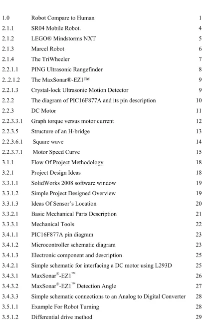
Generally, robot have three main parts known as processor, sensor and motor control system. If robot is replaced by human, sensor is represented eye, controller is represented brain and actuator is represented leg.
Figure 1.0 : Robot Compare to Human
1.1 PROJECT BACKGROUND
This project proposes method to solve the problem of collision avoidance for mobile robots. The project is about mobile robot that is able to detect obstacles and avoid them. The model based on ultrasonic sensor guided the direction, to generate collision free motion. It should be able to detect obstacles before collision occurs. It follows that, the robot should be able to draw conclusion either turns to the left or right. This type of mobile
Human Robot
robot may need to carry out missions in hazardous or populated environments. A typical application is to assist human being in indoor environments, like offices, homes and etc. This project use PIC microcontroller to control the robot. The intelligent of the robot is implementing through PIC preprogrammed in such a why the robot is able to draw conclusion regarding to conditions detected.
1.2 PROBLEM STATEMENT
Nowadays, obstacles avoidance robots usually make collision with an object before turn around. The collision can damage the robot or component inside. So, to make sure the robot not damage because of collision, the ultrasonic sensor for obstacle detection can be perform.
The idea of projects based from the concept of an autonomous vehicle. It is apparent that a future of driverless cars is soon upon us. The motivation of this project is due to the needs of the robot which is able to turn in precise, perfect and quick when it is facing obstacles.
1.3 OBJECTIVE
The main objective of this project is to build An Ultrasonic Guided Obstacle Detection Robot. In order to make this project successful, the objectives have been declared that are:
1. To design a Ultrasonic Guided Obstacle Detection Robot.
2. To create hardware for Ultrasonic Guided Obstacle Detection Robot.
1.4 SCOPE
The scope of this project is to build a robot structure that will function properly according to the objective. This project uses ultrasonic sensor as its sensor. The robot uses a microcontroller for processing the sensor readings and responds by controlling the motors. Lastly, movement direction algorithm should be developed to make sure the product well function as stated in the objective.
1.5 SUMMARY
LITERATURE REVIEW
2.0 INTRODUCTION
Robot can be classified in two categories that are mobile robot and fixed robot [1]. The purpose of this chapter is to explain description for the previous project mobile robot which are mostly used in difficult task or dangerous environment. It also reviewed existing technologies and theory of mobile robot. Besides that, in order to create hardware of the mobile robot the suitable materials must be known and selected.
2.1 OBSTACLE AVOIDANCE MOBILE ROBOT REVIEW
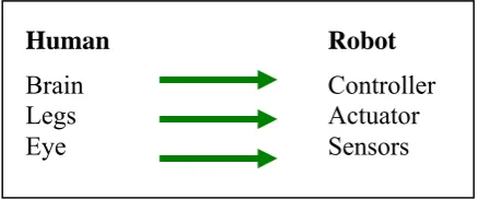
2.1.1 SR04 Mobile Robot
Author : David P. Anderson.
Institution : Department of Geological Sciences, Southern Methodist University. Description :
SR04 is a small mobile robot suitable for exploring human habitats unattended. Two 12-volt DC gear-head motors maneuver the robot in a dual-differential drive configuration, balanced by a non-driven tail wheel caster and powered by a 12 volt 2.2 amp-hour sealed lead acid battery. Sensory input is provided by (in order of priority): front bumper switches, IR collision avoidance, stereo sonar ranging, photo detectors, passive IR motion detection, and shaft-encoder odometry [2].
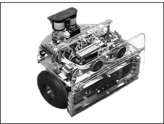
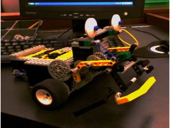
2.1.2 LEGO® Mindstorms NXT
Figure 2.1.2 : LEGO® Mindstorms NXT
Author : Pmocibov Description :
should turn. White wall means „turn 90˚ right“, black one means „turn 90˚ left“ and blue one means „stop“. Robot used light sensor to measure an amount of reflected light from coloured wall and then, depending on the colour of the wall, it turns right or left on spot. A.O.U.S. then again drives straight ahead until it spots another wall and then does the turn. Action is repeated until the robot comes to blue wall when program stops [15].
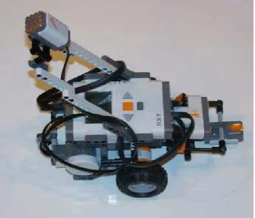
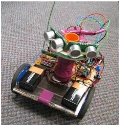
2.1.3 Marcel Robot
Figure 2.1.3 : Marcel Robot
Author : Jordan Bridges (2007) Description :
2.1.4 The TriWheeler
Figure 2.1.4 : The TriWheeler
Author : Chang 'Calvin' Liu (cl457) and Yi 'Tommy' Fan Tang (yft2)
Institution : School of Electrical and Computer Engineering, Cornell University. Discription :
2.2 HARDWARE REVIEW
2.2.1 Ultrasonic Sensor
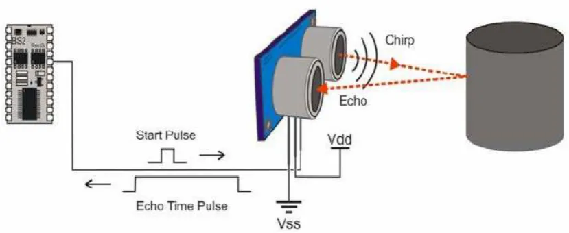
2.2.1.1 PING Ultrasonic Rangefinder
The PING Ultrasonic Rangefinder is a great sensor to add to a robot when the robot needs to know how far it is from an object or obstacle. The rangefinder takes up only one I/O pin on microcontroller. Because it uses only a single I/O pin it needs a unique control algorithm. It sends out an ultrasonic signal from one of its ultrasonic transducers and measures how long it takes for that signal to bounce back to the 2nd ultrasonic transducer. The time can be converted to inches or cm.
Figure 2.2.1.1 : PING Ultrasonic Rangefinder
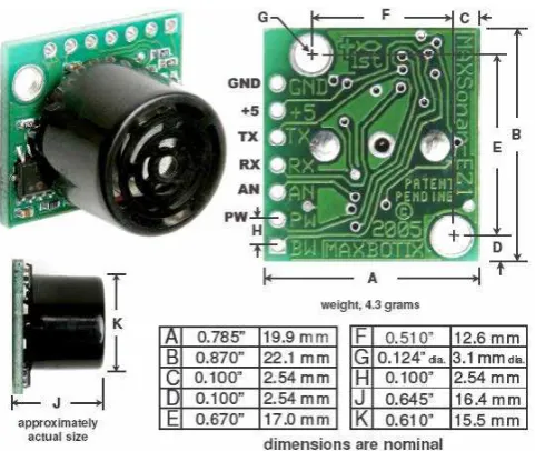
2.2.1.2 The MaxSonar®-EZ1™
Figure 2.2.1.2 : The MaxSonar®-EZ1™
2.2.1.3 Crystal-lock Ultrasonic Motion Detector
A pair of 40 KHz ultrasonic transducers detects moving objects or human bodies up to 10 meters. When any object is found moving in front of the transducers, the detector responds by energizing a miniature relay (LED on) for about 2 seconds. This will repeat continuously until the object stops moving. The transducers are mounted off board via 2 pairs of cables (as shown in the picture ).