Finite element analysis of machining thin-wall parts
R. Izamshah R.A
1,2 a, John P.T Mo
2,b, Songlin Ding
2,c1
School of Aerospace, Mechanical and Manufacturing Engineering, RMIT University, Bundoora Victoria 3083, Australia
2
Faculty of Manufacturing Engineering, Universiti Teknikal Malaysia Melaka, Durian Tunggal, Melaka 76100, Malaysia
a
[email protected], [email protected], [email protected]
Keywords: Finite element analysis, Milling, Thin-wall parts.
Abstract.
In an attempt to decrease weight, new commercial and military aircraft are designs with unitised monolithic metal structural components which contains of thinner ribs (i.e., walls) and webs (i.e., floors). Most of the unitised monolithic metal structural components are machined from solid plate or forgings with the start-to-finish weight ratio of 20:1. The resulting thin-walled structure often suffers a deformation which causes a dimensional surface error due to the action of the cutting force generated during the machining process. To alleviate the resulting surface errors, current practices rely on machining through repetitive feeding several times and manual calibration which resulting in long cycle times, low productivity and high operating cost. A finite element analysis (FEA) machining model is developed in this project to specifically predict the distortion or deflection of the part during end milling process. The model aims to provide an input for downstream decision making on error compensation strategy when machining a thin-wall unitised monolithic metal structural components. A set of machining tests have been done in order to validate the accuracy of the model and the results between simulation and experiment are found in a good agreement.
Introduction
The manufacturing demands faced by the aerospace industry, with experts forecasting 13,000 new aircraft over the next 20 years leads to the production of thin-wall monolithic parts [1]. Airframe designs for modern commercial and military aircraft contain hundreds of unitized monolithic metal structural components which contains of thinner ribs (i.e., walls) and webs (i.e., floors). Thin-wall machining of monolithic parts allows for higher quality and precise parts in less time, impact business issues including inventory and Just-In-Time (JIT) manufacturing. However, because of the poor stiffness, the resulting thin-walled structure often suffers a deformation which causes a dimensional surface error due to the action of the cutting force generated during the machining process. To alleviate the resulting surface errors, current practices rely on machining through repetitive feeding several times and manual calibration which resulting in long cycle times, low productivity and high operating cost.
and the cutting system deflections are solved iteratively by modified Newton-Raphson method. Ratchev et al. [5] investigated the modelling and simulation environment for machining low-rigidity components. Later in his work, Ratchev et al. [6] modelled the material removal process using voxel-based representations by cutting through the voxels at the tool/part contact surface and replacing them with equivalent set of mesh. Recently, Rai and Xirouchakis [7] consider the effects of fixturing, operation sequence and tool path in transient thermo-mechanical coupled milling simulation of thin-walled components.
Despite of significant works on finite element modeling of thin-wall machining has been developed and successfully applied [8-12], there still a need for more efficient approach on modeling the thin-wall machining especially in modeling the real component attribute of the workpiece and cutting tool instead of an idealized geometry such as a cantilever beam and a simple cylinder to represent the cutting tool. A finite element analysis (FEA) machining model is developed in this project to specifically predict the distortion or deflection of the part during end milling process. The model aims to provide an input for downstream decision making on error compensation strategy when machining a thin-wall unitized monolithic metal structural components. A set of machining tests have been done in order to validate the accuracy of the model and the results between simulation and experiment are found in a good agreement.
Surface Error When Machining Thin-Wall Part
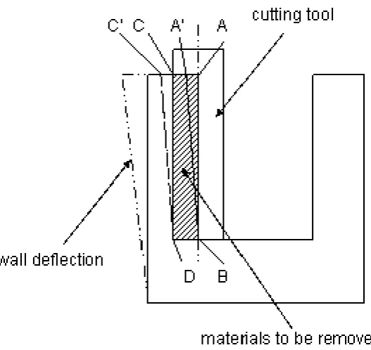
Because of the poor stiffness of thin-wall part, deformation is more likely to occur in the machining of thin-wall part which resulting a dimensional form errors. Fig. 1 shows the machining sketch map that illustrates the deflection of the thin-wall in machining process. The shadow area ABCD represents the material to be removed ideally. However, under the acting of the cutting force, point C and A is shifted to point C’ and A’. Thus, resulting only material A’BCD is remove in practical machining process due to the deflection. After the tool moves away from the milling surface, the wall recovers elastically, and material CDC’ that should be cut remain unremoved resulting the surface errors [16].
Finite Element Models Of Thin-Wall Parts And Helical Endmill
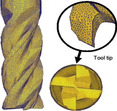
The structural of the thin-wall workpiece and helical endmill are modelled with the three-dimensional tetrahedron solid element. Tetrahedron solid element is preferred because of the complexity of the shape and to capture the change in structural properties of the wall due to material been removed. For the three-dimensional element, each node has three degrees of freedom, i.e, three displacements (δx, δyand δz) and the displacements within each element are interpolated by the nodal values [3]. Fig. 2 and Fig. 3 show the thin-wall component and helical endmill model respectively, for the deflection calculations. Only the removed part is refined for accuracy and to save the computational calculation time. The workpiece is modelled as a plastic object which means it can be deformed and cut by the endmill teeth. Consequently, when the mesh is deformed it must be regenerated frequently, often at every time step. The workpiece mesh must be finer than the cutting tool mesh because the chip geometry can sometimes only be described with very fine elements. The initial wall thickness ti is reduced to tc at the transient zone where the cutter flutes enter and exit the material in the milling process. Only the bottom part of the workpiece is held constrained. For simplicity, in this simulation the cutting tool is assumed to be rigid and the cutter deflection can be neglected.
Fig. 2. Finite element model of thin-wall part.
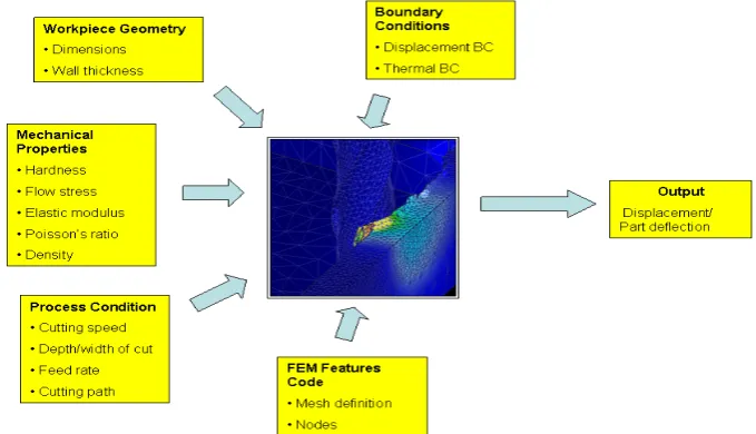
The Lagrangian method is adopted in the machining simulation, in which each individual node of the mesh follows the corresponding material particle during motion [8]. One key advantage of the Lagrangian mesh in simulating the machining process is the ability to know the entire time history of the key variables at every point during the simulation. On the other hand, if a simulation crash for any reason, a new simulation can start where the crashed simulation stopped. This is particularly useful because nearly every simulation has some sort of problem during the run. This is possible because the Lagrangian mesh is reformulated at nearly every time step, in order to manage the deformation of the material. Fig. 4 shows the FEA input for modelling the thin-wall machining.
.
Fig. 4. FEA input for modelling the thin-wall machining.
Model Validation
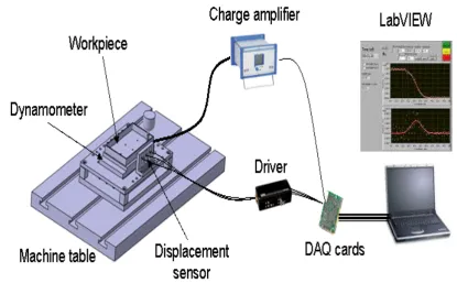
The proposed model was experimentally tested by comparing the simulation results with the results of experiment for an identical set of test components. The geometry of the component used in the simulation and experiment is 150x150x17 mm with 1.8 mm of wall thickness. The radial depth of cut is 0.3 mm and the axial depth of cut is 15 mm. The experimental set-up is shown in Fig. 5. All experimental tests were performed on a HAAS VF1 vertical machining center. Three component Kistler dynamometer (type 9257B) and Kistler charge amplifier (type 5070A) are used to measure the cutting loads, while National Instrument DAQ card is used to acquire the signal. The wall deflection is measured using three Lion Precision ECL 130 inductive displacement sensors. The sensors are mounted at three different equal locations (37.5, 75 and 112.5 mm) at the back of the workpiece. Both the signals from the dynamometer and displacement sensors are then been analyse using LabVIEW 8.5.1.
Table 1. Chemical compositions of Ti-6Al-4V alloy (wt. %).
Chemistry N C H O Fe Al V Ti Other el.
% w/w, min. - - - 5.50 3.50 - -
% w/w, max. 0.05 0.10 0.0125 0.20 0.30 6.75 4.50 Balance 0.40
Table 2. Mechanical properties of Ti-6Al-4V alloy at room temperature.
Density
[kg/m3]
Young’s modulus [GPa]
Poisson ratio Yield strength
[MPa]
Hardness
[HB]
Elongation
[%]
4430 113.8 0.34 880 334 14
Fig. 5. Experimental set-up.
Table 3. Parameter used for simulation and experiment.
Tool 4 flutes carbide flat endmill Tool diameter 6 mm
Helix angle 38o
Ramp down angle 5o
Cutting speed 4244 rpm
Feed rate 340mm/min
Axial cutting depth 15 mm
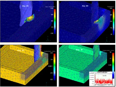
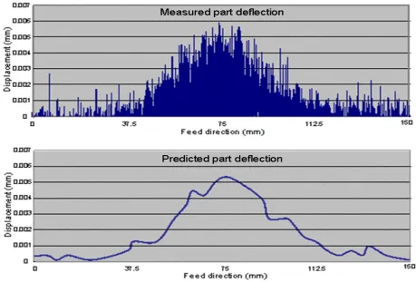
Fig. 6 shows the simulation during the machining process. The top row shows the stress and temperature state during the machining process. The bottom row shows the calculated displacement at the cutter feed location. Fig. 7 shows the comparison between simulation and experiment. It can be seen that the predicated displacement matches those measured in the cutting tests very well. The deflection of the workpiece is small at both ends and maximum at the middle region. In this two graphs it can be seen clearly that the displacement and its variation obtained from simulation follow the same pattern and trend of those measured in the cutting test, which indicates the proposed model is valid. Once the deflection of the workpiece is established, it can be used for further investigation on error compensation strategy.
Fig. 7. Results comparison between simulation and experiment.
Conclusions
In aerospace industry, accuracy of machined components is one of the most critical considerations for many manufacturers especially in where most of the part used unitised monolithic metal structural components which contains of thinner ribs (i.e., walls) and webs (i.e., floors). In the current work, a finite element analysis (FEA) model is developed to specifically predict the distortions or displacements for machining thin-wall component. The thin-wall component and helical fluted endmill is modelled with three dimensional isoparametric tetrahedron elements, which can accurately model the specific geometry and structural behaviour of the part and the endmill. A set of machining tests have been done in order to validate the accuracy of the model and the results between simulation and experiment are in a good agreement. The FEA deflection model would be an efficient means for analysing the root cause of errors induced during machining of thin-wall parts and provide an input for downstream decision making on error compensation. On the other hands, through the FEA deflection model, manufacturers can further enhance their productivity by eliminating the need of expensive preliminary cutting trials often require for validating the designed machining process plan.
References
[1] Information on http://www.makino.com/about/article/10-1-2002/Thin_Wall_Machining
[2] E. Budak, Y. Altintas, Peripheral milling conditions for improved dimensional accuracy, Int. J. Mach. Tools Manuf. 34 (1994) 907-918.
[4] M.A Elbestawi, R.Sagherian, Dynamics modelling for the prediction of surface errors in the milling of thin-walled sections, J. of Materials Processing Technology 25 (1991) 215-228.
[5] S.Ratchev, W.Huang, S.Liu, A.A Becker, Modelling and simulation environment for machining of low-rigidity components, J. of Materials Processing Technology 153-154 (2004) 67-73.
[6] S.Ratchev, W.Huang, S.Liu, A.A Becker, Milling error prediction and compensation in machining of low-rigidity parts, Int. J. of Mach. Tools Manuf. 44 (2004) 1629-1641.
[7] J.K Rai, P.Xirouchakis, Finite element method based machining simulation environment for analyzing part errors induced during milling of thin-walled components, Int. J. of Mach. Tools Manuf. 48 (2008) 629-643.
[8] Liu Gang, Study on deformation of titanium thin-walled part in milling process, J. of Materials Processing Technology 155-156 (2008) 1383-1389.
[9] M. Wan, W.H. Zhang, Calculations of chip thickness and cutting forces in flexible end milling, Int. J. of Adv Manuf. Tech. (2006) 637-647.
[10] S.Ratchev, E. Govender, S. Nikov, K. Phuah, G. Tsiklos, Force and deflection modelling in milling of low-rigidity complex parts, Int. J. of Materials Processing Technology 143-144 (2003) 796-801.
[11] S.Ratchev, S.Liu, W.Huang, A.A Becker, A flexible force model for end milling of low-rigidity parts, Int. J. of Mach. Tools Manuf. 153-154 (2004) 134-138.
[12] M. Wan, W.H. Zhang, G.H Qin, Z.P Wang, Strategies for error prediction and error control in peripheral milling of thin-walled workpiece, Int. J. of Mach. Tools Manuf. 48 (2008) 1366-1374.
[13] W. Chen, J. Xue, D. Tang, H. Chen, S. Qu, Deformation prediction and error compensation in multilayer milling process for thin-walled parts, Int. J. of Mach. Tools Manuf. 49 (2009) 859-864.
[14] M.C. Yoon, Y.G Kim, Cutting dynamic force of endmilling operation, J. of Materials Processing Technology 155-156 (2004) 1383-1389.
[15] E.Budak, Analytical models for high performance milling. Part 1: Cutting forces, structural deformations and tolerance integrity, Int. J. of Mach. Tools Manuf. 46 (2006) 1478-1488.