MOVING VEHICLE TRAFFIC CONTROLLER
Shafrein Izwan Bin Hasshim
i
“I hereby declared that I have read through this report and found that it has comply the partial fulfillment for awarding the degree of Bachelor of Mechatronic Engineering”
Signature : _______________________________________
Supervisor’s Name : PROF MADYA MOHD ARIFF BIN MAT HANAFIAH
ii
MOVING VEHICLE TRAFFIC CONTROLLER
SHAFREIN IZWAN BIN HASSHIM
This Report is submitted in partial fulfillment of requirements for the Degree of Bachelor in Mechatronic Engineering
Faculty Of Electrical Engineering
UNIVERSITI TEKNIKAL MALAYSIA MELAKA
iii
DECLARATION
“I hereby declared thatthis report entitled ‘Moving Vehicle Traffic Controller is a result of my own work except for the excerpts that have been cited clearly in the references.”
Signature : _______________________
iv
DEDICATION
v
v ACKNOWLEDGEMENTS
First of all, I would like to express my thankfulness and gratitude to Allah S.W.T who has given me all the strength that I needed to complete this final year project (FYP 2) and also to prepare this report.
With this opportunity, I would like to express my gratitude to the Faculty of Electrical Engineering (FKE), Universiti Teknikal Malaysia Melaka (UTeM) generally, and especially to my supervisor Prof. Madya Mohd Ariff Bin Mat Hanafiah for the help, advices and guidance that he gave during this project.
vi
ABSTARCT
vii
ABSTRAK
ix
2.7 Sixth Review 25
3 PROJECT BACKGROUND
3.1 Project Background 29
3.2 Programmable Logic Controller (PLC) 30
3.3 Theory of Sensors 33
3.4 Theory of Pneumatics 35
4 METHODOLOGY
4.1 Introduction 40
4.2 Process flowchart of the project 42
4.3 Project methodology 43
5.2 Traffic Light at Four Junction Operation 66
x
LIST OF TABLES
TABLE TITLE PAGE
4.1 Gantt chart 44
4.2 Sensor specification 50
4.3 Input Components 56
4.4 Output Components 57
xi
LIST OF FIGURES
FIGURE TITLE PAGE
1.1 Controller System 2
2.1 VANET System 6
2.2-2.10 Traffic light using MATLAB Simulation 9-14 2.11 Fuzzy logic controller for 4-lane traffic 18
2.12 Input Fuzzy Variable 19
2.13 20 output sequencing circuit PCB 20
2.14 20 Output Sequencing Circuit 21
2.15 20 Step LED Circuit 23
2.16 20 Step Traffic Light Schematic 24
2.17 20 Output Sequencing Circuit PCB 26 2.18 20 Output Sequencing Circuit Diagram 26
2.19 MEL-12 Sensor Position 28
3.1 5 major parts of the project 29
3.2 Flows of PLC’s input and output section 32
3.3 Capacitive Sensor 33
3.4 Photoelectric Sensor 34
3.5 Solenoid valve 37
3.6 Pneumatic Cylinders 38
4.1 Project Process Flowchart 42
4.2 Flowchart of project methodology 43
4.3 Track Design 45
4.4 Car Track Design 46
4.5 Train Track Design 46
xii
4.7 Prototype model of the track 48
4.8 Car track 49
4.9 Sensor Output Circuit 50
4.10 Through-beam sensor Emitter circuit 51
4.11 Sensor Adjustment 51
4.19-4.26 SCADA development 61-65
5.1 LED Traffic Light 66
5.2 Moving Vehicle Traffic Light Controller Model 67
5.3-5.4 Traffic Light Output 68-69
CHAPTER 1
INTRODUCTION
1.1 Definition
A control system is a device or set of devices to manage, command, direct or regulate the behaviour of other devices or systems. This project is categorized in on/off control. In most applications of on-off feedback control, some consideration needs to be given to other costs. Therefore, practical on-off control systems are designed to include hysteresis, usually in the form of a deadband, a region around the setpoint value in which no control action occurs. The width of deadband may be adjustable or programmable. Larger more complex systems can be controlled by a Distributed Control System (DCS) or Supervisory Control and Data Acquisition (SCADA) system.
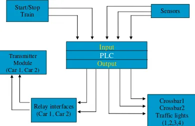
1.2 Project Overview
2
Figure 1.1: Controller System
1.3 Problem statements
To reduced manpower to operate the train gate across the road.
System operated by human that is not efficient in handling traffic movement.
Unexpected incident due to lack of awareness of the train gate operator.
The existing system is static and very hard for student to understand.
3
1.4 Objectives of the project
The project is aimed to meet the following objectives:
To design a model of roadway system that can simulate the operation of
traffic control system.
To design a wireless control car using a relay interface that can get signals from the roadway.
To design an automatic crossbar that utilizes the uses of pneumatic.
To build a model kit to portray the traffic system for students.
1.5 Scope of the project
CHAPTER 2
LITERATURE REVIEW
2.1 Introduction
Several numbers of books, catalogues, technical manuals and also on-line references have to be studied in order to identify and come-up with suitable hardware, components, and software to make this project successful. The existing control systems can also be referred for further improvement.
2.2 First Review: Traffic Light System Using BASIC STAMP 2 (BS2)
Many traffic light systems operate on a timing mechanism that changes the lights after a given interval. An intelligent traffic lights system senses the presence or absence of vehicles and reacts accordingly. The idea behind intelligent traffic system is that drivers will not spend unnecessary time waiting for the traffic lights to change.
5
The traffic signal system consists of three important parts. The first part is controller, which represents the brain of the traffic system. It consists of a computer that controls the selection and timing of traffic movements in accordance to the varying demands of traffic signal as registered to the controller unit by sensors [2]. The second part is the signal visualization or in simple words is signal face. Signal faces are part of a signal head provided for controlling traffic in a single direction and consists of one or more signal sections. These usually comprise of solid red, yellow, and green lights. The third part is the detector or sensor. The sensor or detector is a device to indicate the presence of vehicles. One of the technologies today, consists of wire loops placed in the pavement at intersections. They are activated by the change of electrical inductance caused by a vehicle passing over or standing over the wire loop. Recent technology utilization is video detection. A camera feeds a small computer that can “see” if a vehicle is present.
BASIC STAMP 2 (BS2) is used as the microcontroller of the traffic signal. The BS2, which needs to be plugged to the Board Education (BoE), is directly attached to the computer in order to program it.
2.3 Second Review: Traffic Lights Using Car-to-Car Communication
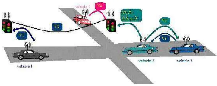
Advances in mobile computing and wireless communication have offered new possibilities for Intelligent Transportation Systems (ITS), aiming at improving driving safety and traffic efficiency. By adding short-range wireless communication capabilities to vehicles, the devices form a mobile ad-hoc network, allowing cars to exchange information about road conditions. This is referred as Vehicular Ad-hoc Networks (VANETs) [3].
6
The paper examines the possibility of deploying an adaptive signal control system in intersections, a system that can base its control decision on information coming from cars. It is assume that each vehicle is equipped with a short-range wireless communication device, as is a controller node placed in the intersection with traffic lights (figure 2.1).
Figure 2.1: VANET System
There are several goals that can be taken into consideration when designing a signal control mechanism, like minimizing the average delay of vehicles approaching an intersection, increasing progression by coordinating vehicle platoons between intersections, reducing the queue length of all approaches to an intersection and even reducing overall fuel consumption and pollutant emissions.
7
intersections, the degree of saturation is calculated through the demand per capacity ratio which is greater than 1.
Several adaptive traffic control systems have been implemented for intersections all over the world. Some of the most important ones include Split, Cycle and Offset Optimization Technique (SCOOT) and Sydney Coordinated Adaptive Traffic System (SCATS) [4]. SCOOT is based on loop detectors placed on every link to an intersection, usually at the upstream end of the approach. Other systems, including SCATS, have detectors placed immediately before the stop line at an intersection. Thus, they cannot get accurate data when the queue grows beyond the length of the detector, or the link is over saturated. Since they use a model based especially on occupancy, they also have difficulties in differentiating between high flows or intersection stoppage. Reported research shows poor performance when incidents occur.
Adaptive traffic lights based on wireless communications with the vehicles can employ greater flexibility than the ones mentioned above as they are provided with more information for the signal decision process (e.g. vehicles positions and speeds). The cost is also significantly lower considering loop detectors are usually installed in the asphalt under each lane approaching the intersections and cameras require high processing power. If all vehicles will be equipped with wireless communication devices, then all that is needed is wireless devices with some processing power in intersections.
By making use of wireless communication and GPS, it enables vehicles to collect and disseminate traffic information and, finally, to provide meaningful data to the driver. Vehicles periodically transmit information about themselves and other cars they know about. They use one-hop broadcasts to avoid a broadcast storm. Each record consists of a position, identification number, speed, direction, state and a timestamp of the moment when the information was created.
8
controllers in adjacent intersections may communicate through a wired network, in order to provide each other with additional information. For every vehicle record received, the controller checks it against its local database. If the vehicle wants to pass through the controlled intersection and there is no newer record about this vehicle in the database, the record will be stored and taken into account when calculating link parameters.
The control method benefits from the wireless communication system with vehicles and can accurately determine traffic metrics. The most important metrics were use are control delay and queue length. The control delay is calculated for each car that passes through an intersection. It is the difference between the estimated travel time in the absence of the intersection control and the travel time reported by a vehicle, in the presence of the intersection control. The queue length is computed by the traffic controller, which knows the traffic configuration at every moment.
The controller keeps track of the vehicles throughout the entire period when they are in a few miles range around the intersection (through the information propagation scheme of Traffic View), so it is able to measure accurately both volume and demand. The timing plan generation process takes place once during each cycle and establishes a plan for the following cycle based on the measured parameters [3].
9
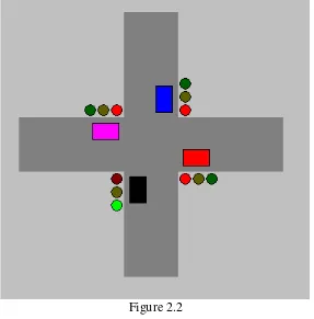
2.4 Third Review: Traffic Light Control Simulation Using MATLAB
Consider a situation where there is a junction. In order to ensure that the flow of the traffic run smoothly, traffic lights are very much needed. So in this simulation program, several parts are constructed, four functional traffic lights and four cars that can move when a traffic light at their junction turns green (figure 2.2).
Figure 2.2
10
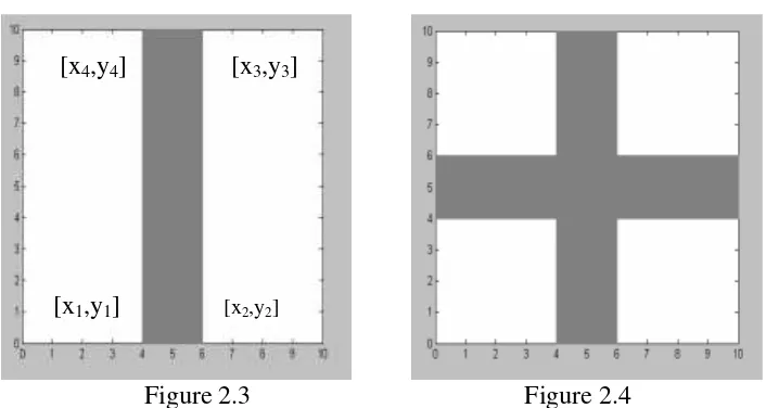
[x4,y4] [x3,y3]
[x1,y1] [x2,y2]
Figure 2.3 Figure 2.4
fill is a MATLAB function to create a polygon defined by column vector x and y as in figure 2.3 and 2.4.
fill([x1 x2 x3 x4], [y1 y2 y3 y4], ...
‘face color’, [.5 .5 .5], ‘edge color’, [.5 .5 .5]);
Create a vertical road.
fill ([4 6 6 4],[0 0 10 10], [.5 .5 .5], 'edge color', [.5 .5 .5])
Create a horizontal road.
fill ([0 10 10 0],[4 4 6 6], [.5 .5 .5], 'edge color', [.5 .5 .5])
11
t = 0:pi/20:2*pi;
Circle=fill(x + r*sin(t), y + r*cos(t), 'r');
With r as radius for the circle; and x and y is the center point of the circle. Positioning those circles at every junction with respect to the traffic light color order.