i
“I hereby declared that I have read through this report and found that it has comply the partial fulfillment for awarding the degree of Bachelor of Electrical Engineering
(Mechatronic)”
Signature : ………
Supervisor’s Name : ……….
ii
MOBILE TRAFFID LIGHT FOR EMERGENCY VEHICLE
MOHAMAD AZFAR BIN SAZALI
This Report Is Submitted In Partial Fulfillment of Requirements for the Degree of Bachelor in Electrical Engineering (Mechatronic)
Fakulti Kejuruteraan Elektrik Universiti Teknikal Malaysia Melaka
iii
“I hereby declared that this report is a result of my own work except for the excerpts that have been cited clearly in the references.”
Signature :………..
Name :………..
iv
AKCNOWLEGDEMENT
Asssalamuakaikum..
First and foremost, I would like to thank to my supervisor Pn. Ainain Nur Binti Hanafi who had taken a lot of efforts to meticulously go through my Final Year Project 1 and came up with helpful suggestion. Without helping from her, we surely came into deep problem in completing this report to fulfill the requirement in FYP II.
Besides that, I’ am indebted to the numerous people who have contributed their time, effort, advice, help and constructive criticism throughout my project for FYP II on MOBILE TRAFFIC LIGHT FOR EMERGENCY VEHICLE. Finally, I would like to express my heartfelt gratitude to my family and friends for their support, constructive suggestion and also criticism.
v
ABSTRACT
vi
ABSTRAK
Kesesakan lalu lintas fenomena yang memberi impak yang besar terhadap sistem pengangkutan negara kita. Hal ni menyebabkan pelbagai masalah timbul terutama bila berlakunya kes-kes kecemasan di kawasan simpang empat yang sentiasa sibuk dan padat dengan kenderaan. Tambah merumitkan apabila laluan khas tidak disediakan untuk kenderaan kecemasan contohnya ambulans, polis dan bomba untuk tujuan kecemasan ketika lampu isyarat merah (berhenti). Bagi mengatasi masalah ini, satu sistem kawalan lampu isyarat untuk kenderaan kecemasan direkabentuk. Dengan mengunakan kaedah komunikasi Frekuensi Radio (RF) dan
vii
TABLE OF CONTENT
CHAPTER TITLE PAGE
PROJECT TITLE iii
DECLARATION v
ACKNOWLEDGEMENT vi
ABSTRACT vii
ABSTRAK viii
TABLE OF CONTENTS ix
LIST OF TABLES xii
LIST OF FIGURES xiii
LIST OF SYMBOLS AND ABBREVIATIONS xiv
LIST OF APPENDICES xv
1 INTRODUCTION 1
1.1 Project Overview 1
1.2 Project Objective 2
1.3 Statement of Problem 3
1.4 Scope of Project 3
1.5 Executive Summary 3
2 LITERATURE REVIEW 5
2.1 Introduction 5
2.1.1 Case 1 5
2.1.2 Case 2 6
2.1.3 Case 3 7
2.1.4 Case 4 8
2.1.5 Case 5 8
viii
3 THEORETICAL BACKGROUND 11
3.1 Traffic light 11
3.2 Radio Frequency 12
3.2.1 Special properties of
RF electrical signals 14 3.3 PIC (Programmable Integrated Controller) 15
3.3.1 PIC feature 15
3.3.2 PIC 16F877A specification 17
4 METHODOLOGY 19
4.1 Introduction 19
4.2 Project progress procedure 19 4.2.1 Methodology general description 21
5 SOFTWARE DEVELOPMENT 23
5.1 Introduction 23
5.2 Software Development 23
5.2.1 Construct overall emergency
traffic light algorithm 24 5.2.2 Construct normal traffic light
Algorithm 26
5.2.3 Construct normal traffic light
PIC output algorithm 27 5.2.4 Design traffic light system
circuit by using software Proteus 28 5.3 Develop C language programming
using MicroC software 29
5.4 Design traffic light system circuit
ix
6 HARDWARE DEVELOPMENT 32
6.1 Introduction 32
6.2 Hardware development 32
6.2.1 Procedure 1 33
6.2.2 Procedure 2 36
6.2.3 Procedure 3 37
6.2.4 Procedure 4 38
6.2.5 Procedure 5 40
6.2.6 Procedure 6 43
6.2.7 Procedure 7 44
7 EXPERIMENT & ANALYSIS 45
7.1 Introduction 45
7.2 Experiments on RF Module 45
7.3 Problem analysis 47
7.3.1 Programming development 47 7.3.2 Radio Frequency Module 48
7.3.3 Wiring 49
7.4 Achievement 49
8 CONCLUSION & RECOMMENDATION 50
8.1 Introduction 50
8.2 Conclusion 50
8.3 Recommendation 51
REFERENCES 52
x
LIST OF TABLE
NO TITLE PAGE
3.1 Table of frequency of electromagnetic
radiation spectrum 14
5.1 Four junction traffic light sequence (normal) 26
5.2 PIC output sequence (normal) 27
5.3 Integral types and keywords in parentheses 30 6.1 RF transmitter module specification 40 6.2 RF transmitter module pin description 40 6.3 RF receiver module specification 41 6.4 RF receiver module pin description 41 7.1 Transmitter and receiver voltage
xi
LIST OF FIGURE
NO TITLE PAGE
2.1 Emergency vehicle frequency waveform 6
2.2 Four junction traffic light 7
2.3 Side view between emergency
vehicle and other vehicle 8
2.4 Tricolors traffic light 10
2.5 Emergency icon 10
3.1 4-state lights warn traffic 11
3.2 Computerized traffic control box 12
3.3 PIC16F877A 16
5.1 Emergency traffic light system
circuit simulation 31
6.1 Top and bottom view for left
side of prototype base 34
6.2 Top and bottom view for right
side of prototype base 34
6.3 Four junction layout 35
6.4 Layout of four junction prototype 35
6.5 Hole for traffic light, receiver and wiring
layout on Styrofoam board 36
6.6 Four junctions’ layout on cardboard 36
6.7 Constructed hole on Styrofoam board 37
6.8 Traffic light and receiver prototype 37
6.9 Solid Work 2007 traffic light prototype design 38
6.10 Traffic light prototype 39
6.11 Traffic light prototype circuit 39
xii
6.13 RF receiver module 41
6.14 Transmitter circuit 42
6.15 Transmitter with casing 42
6.16 Receiver circuit 42
6.17 Receiver with casing 43
6.18 Wiring scheme by Proteus 6 Professional 43 6.19 Top view for overall project wiring scheme 44
6.20 Complete prototype 44
7.1 Transmitter circuit 46
7.2 Transmitter circuit 46
xiii
LIST OF FLOW CHART
NO TITLE PAGE
3.1 Overall flow chart 20
5.1 Overall emergency traffic light algorithm 24
xiv
LIST OF SYMBOLS AND ABBREVIATIONS
PIC - Peripheral Interface Controller
RF - Radio Frequncy
PID - Proportional Integration Derivation
V - Voltage
A - Ampere
Ω - Ohm
SCADA - Supervisory Control and Data Acquisition CAD - Computer Aided Design
xv
LIST OF APPENDICES
APPENDIX TITLE PAGES
A Project planning 53
B Source Code of four junction traffic
light for emergency vehicle system. 54
B User's Manual RF_RX_v1 57
1
CHAPTER 1
INTRODUCTION
1.1 Project Overview
Malaysia is among developed country and also known as new industrial country. As we know, the term of development can be classified with improvement in every province. As an example, an improvement is need in prefect convolution of roadway convenience. This is because roadway is most important transportation element.
Moreover, with Malaysian level as a growing country in development, the land transportation system become dominant and the system are completely used to produce every activity regarding to human need. Meanwhile, roadways are the most efficient, faster and reduce transportation cost in domestic transportation system. With advance convolution of roadway convenience, Malaysia can compete with other developed countries such as Singapore, Hong Kong, Korea and Taiwan.
2
The extreme increasing number of vehicle will cause a difficulty among traffic movement in the country. Traffic jams are happening in city area especially in Kuala Lumpur, and different cities have different context of traffic jam problem. In Kuala Lumpur context, “Single Occupancy Vehicle” (SOV) is the number one factor in traffic jam problem. More than that still have other factor such as human behavior, traffic light system and other.
Miscellaneous of effect are recorded base to this traffic problem. Taking one of these problems than can be focused is emergency vehicle problem. An emergency vehicle can be categories as ambulance, police car, fire engine and VIP vehicle. As we all know, the emergency vehicle not really use the road compare to other private vehicle, this is because the emergency vehicle will needed when emergency case occur only. As an example, the ambulance vehicle will be very important in term of time because will be involved human life and need to rushing to hospital to get emergency treatment. In addition, with the normal traffic light system, more time will be wasted by the ambulance to arrive to the destination. To solve this problem, a continuous research and improvement of the system must be done.
1.3 Project objective
The objectives of the project are to apply the Radio Frequency Communication in traffic light control system for emergency vehicles. Beside that, to develop an algorithm for traffic light controller with emergency mode when the emergency vehicle switch ON the emergency system. Therefore, the developments of a prototype of the new junction’s traffic light system are needed to upgrade the traffic light system technology in Malaysia.
1.4 Problem statement
3
to control the traffic jam when emergency situation occurs. The traffic becomes more worst because other vehicle had to huddle for given route to emergency vehicle. Moreover, an emergency vehicle has to avoid the traffic red light (stop) for emergency purpose. This situation will cause another accident between vehicles from the other junction. The following problem will be solving when this project applied to the real life soon. In hope it will reduce the difficulty for the emergency vehicle soon.
1.5 Project scope
Generally, every project or task have it own scope as a guideline for accomplish it. For this project, the scope is limited to certain selected fields, which are design a four junction’s traffic light control system at main road using only timer controller. To specify the scope, the system will be implemented at four junction’s traffic light where a main route to hospital or clinic. Beside that, this system will been prefer only in an emergency vehicles especially ambulance. In addition to improve this project control system, implementation of RF transmitting device [4] (to transmit signal up to 100 meters) and receiving device (receive RF signal from any 315MHz transmitter) via radio signal are very needed [3]. Beside that, design software coding using MicroC software to implement to the traffic light system and the system flow controlled by PIC microcontroller.
1.6 Executive Summary
4
5
CHAPTER 2
LITERATURE REVIEW
2.1 Introduction
In every state along the globe are facing very large problem regarding to traffic light junction that cause accident between emergency vehicle and other public vehicle. Conducting literature review prior to undertaking research project is critical as this will provide much needed information on the technology available and methodologies used by other research counterparts around the world on the topic. This chapter provides the summary of literature reviews on key topics related to balancing a two-wheeled robot. Below are the several previous projects related to this project:
2.1.1 (Emergency traffic control system with security transmission coding by
Levi L. Rose)
6
Figure 2.1: Emergency vehicle frequency waveform.
2.1.2 (Emergency vehicle warning and traffic control system by Michael R.
Smith, Paul J. Davidson and Henry L. Pfister)
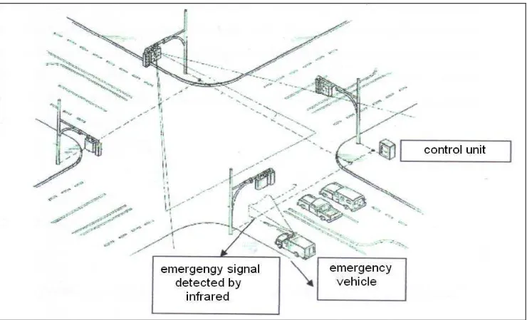
This traffic light system designed to give early warn to the emergency vehicle to find a way out from traffic jam and will easy the emergency vehicle reach to the destination more faster. This method, early emergency warn, will appeared to give direction where approaching of emergency vehicle. Beside that, it will be showed the traffic jam area at every junction.
The emergency vehicle transmitter device will transmit the emergency signal when any emergency situations occur. This signal will be received directly by receiver with infrared (I.R) interface. The receiver will be placed at every junction and operated to receive the signal from transmitter. The controller will process the transmitted data or signal from receiver and control all traffic light system operation and traffic movement where the junction that emergency vehicle located.
The controller also provides the output for display as a messages and symbol regarding to the path of emergency vehicle at every junction. In addition, the display system also displayed the emergency vehicle position where the emergency vehicle
TIME
CODE
TRANSMITTED CODE BY EMERGENCY
7
[image:22.595.135.505.155.380.2]has past trough the junction or not. After emergency vehicle past trough the junction, automatically system for emergency vehicle will deactivate and system turn to normal.
Figure 2.2: Four junction traffic light.
2.1.3 (Traffic light control for emergency vehicle by Wilbur L. Mitchell)
A traffic light control system for overcome the traffic jam problem and make easier to emergency vehicle obtain a emergency path where the radio transmitter and antenna provided in the emergency vehicle. The radio will transmit the signal to the other vehicle that nearby. The radio receiver had been placed at four junction traffic light to receive the emergency signal from emergency vehicle that passed by the junction. The first signal code contains a frequency for emergency vehicle but the second signal code contains a frequency for other vehicle.
8
2.1.4 (Emergency vehicle detection system by William E. Brill)
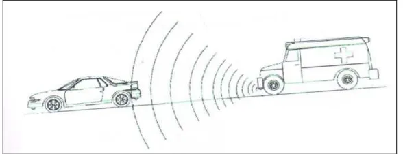
[image:23.595.173.467.426.539.2]This system is the system to detect the emergency vehicle approaching. This system to alarm the other driver that emergency vehicle are approaching to have a way through. This system also equipped with a sound sensor to all vehicle and a device produce emergency sound to emergency vehicle (especially ambulance). The device at emergency vehicle will produce and transmit a sound signal. For the emergency vehicle attending a emergency situation, a switch will activate to produce sound signal and it will connected to siren. When the siren was activated, automatically the sound signal produces a waveform to alarm the driver in front of the emergency vehicle. The driver will received it trough a display panel in vehicle and the display panel will set the poles or waveform pattern of the emergency vehicle. When the emergency vehicle transmits the sound wave, the sound transduction will read this wave for get a confirmation about the vehicle type. If has a similarity of the emergency vehicle pole, other vehicle must give a way trough for the emergency vehicle.
Figure 2.3: Side view between emergency vehicle and other vehicle
Figure 2.3 shows the wave produce by ambulance then the other vehicle in front will give a way trough. Ambulance will have an emergency path because other vehicles no need to huddle.
2.1.5 (Traffic signal light control for emergency vehicles by Carl J. Obeck)
9
that must been trough. The system was containing several poles and pattern about expected response that will be happen to control the traffic flow. That mean, this system has a very effective method to control traffic flow that always busy cause by a lot commuter.
This traffic light controller mechanism will receive the signal from emergency vehicle then it will find a pole to emergency situation and than give command to traffic light to give the emergency vehicle a way trough. The poles storage system for controlling the traffic light will sent the response via all traffic flow situation to the controller. The system will stored much more pales and pattern about expected response of traffic light to control the traffic floe especially at four junction road. Although, this system still not perfect because it can’t operated when there in certain situation doesn’t satisfied before.
2.1.6 (Automated traffic control system having an interactive emergency
vehicle warning therein by Jeremiah W. Pearson)
Traffic flow priority system define as the system that executed by emergency vehicle at four junction traffic light. A signal designed as a secondary electronic signal and an amplifier system, electronically as a source and it will be transmit to the traffic light controller as tricolors traffic light.