DUAL POLARIZATION RECONFIGURABLE ANTENNA
NUR SHAHEERA ALIA BINTI SADICK ALI
This Report Is Submitted In Partial Fulfillment of the Requirements for the Bachelor Degree in Electronic Engineering (Wireless Communication)
Faculty of Computer Engineering and Electronic Engineering. Universiti Teknikal Malaysia Melaka
iii
DECLARATION
“I hereby admit that this report is my own work except that every such summaries and excerpts only have me explain the source.”
Signature :………
Name : NUR SHAHEERA ALIA BINTI SADICK ALI
iv
SUPERVISOR APPROVAL
"I acknowledge that I have read this work in my / THIS work is sufficient in scope and quality for the award of a Bachelor of Electronic Engineering (Wireless Communication).”
Signature :………
Name : DR. MOHAMAD ZOINOL ABIDIN BIN ABD AZIZ
v
DEDICATION
vi
ACKNOWLEDGEMENT
First of all, thank to our creator, "ALLAH" for the continuous blessing and for give me the strength and chances to complete this study.
I would like to express my appreciations to Dr. Mohamad Zoinol Abidin Bin Abd Aziz for their advice during my research. As my supervisors, he has constantly encouraged me to be in focus hardly towards achieving my goal. His observations and comments helped me to establish the overall direction of the research and move forward with in depth investigations.
I am extremely indebted to my family especially my parents for their endless love and emotional support which has brought me this for in my life.
vii
ABSTRACT
viii
ABSTRAK
ix
CONTENTS
CHAPTERS TITLE PAGE
PROJECT TITLE i
PROJECT APPROVE FORM ii
DECLARATION SUPERVISOR APPROVAL DEDICATION ACKNOWLEDGEMENT ABSTRACT iii iv v vi vii
ABSTRAK viii
CONTENTS ix
LIST OF FIGURES LIST OF TABLES
xii xiv LIST OF ABBREVIATIONS
LIST OF APPENDICES
xvi xvii
I INTRODUCTION
1.1 Problem statement 2
1.2 Objective 4
1.3 Project scope 4
x
II LITERATURE REVIEW
2.1 Fading 7
2.2 Diversity 8
2.3 Polarization 9
2.4 Polarization of antenna 11
2.5 Reconfigurable antenna 12
2.6 Type of antenna reconfiguration 12
2.7 Reconfiguration techniques 13
2.8 Electrical reconfigurable antenna
2.8.1 Reconfigurable antenna based on RF-
MEMS
2.8.2 Reconfigurable antenna based on PIN Diodes
2.8.3 Reconfigurable antenna based on Varactors
14 15
15
16
2.9 Optically reconfigurable antenna 17
2.10 Physically reconfigurable antenna 17
2.11 PIN Diode 17
III METHODOLOGY
3.1 Antenna design process 19
3.2 Design specification 22
3.3 Square Patch Linear Polarization Antenna (Design 1)
23
3.4 Square Patch Circular Polarization Antenna (Design 2)
25
3.5 Square Patch Dual Polarization Antenna (Design 3)
xi
3.6 Square Patch Tri-Polarization Antenna (Design 4)
27
3.7 Simulation process 28
3.8 Fabrication process 30
3.9 Measurement process
3.9.1 Return loss measurement 3.9.2 Radiation pattern measurement 3.9.3 Gain measurement
31 31 32 33
IV RESULT AND DISCUSSION
4.1 Square Patch Linear Polarization Antenna (Design 1)
35
4.2 Square Patch Circular Polarization Antenna (Design 2)
40
4.3 Square Patch Dual Polarization Antenna (Design 3)
44
4.4 Square Patch Tri-Polarization Antenna (Design 4)
52
4.5 Data Comparison and Analyses 58
V CONCLUSION AND FUTURE WORK
5.1 Conclusion 5.2 Future work
xii
LISTS OF FIGURES
No Title Page
1.1 Flow chart 6
2.1 Fading occur during multipath propagation 8
2.2 Type of diversity 9
2.3 Direction of polarization 10
2.4 Classification of polarization 11
2.5 Electric field of polarize 11
2.6 Type of antenna reconfiguration 13
2.7 Reconfiguration techniques 14
2.8 Different type of switch 14
2.9 PIN Diode 15
2.10 Equivalent circuit of PIN Diode 16
2.11 Varactor Diode 16
2.12 Equivalent circuit of varactor diode 16
2.13 PIN Diode BAR50-02V 18
3.1 Flow chart of design process 21
3.2 Antenna design of Design 1 23
3.3 Antenna design of Design 2 26
3.4 Antenna design of Design 3 27
3.5 Antenna design of Design 4 28
3.6 Condition of biasing circuit 29
3.7 Reconfiguration technique 29
3.8 Flow chart of fabrication process 30
3.9 Additional design of fabrication process 31
xiii
3.11 Setup of anechoic chamber 32
3.12 Setup of gain measurement 34
4.1 Antenna design of Design 1 36
4.2 Simulation and measured return loss results of Design1 37 4.3 Radiation pattern results of Phi 0, Phi 90 and Theta 90 38
4.4 Antenna design of Design 2 40
4.5 Simulation and measured return loss results of Design2 41 4.6 Radiation pattern results of Phi 0, Phi 90 and Theta 90 43
4.7 Antenna design of Design 3 45
4.8 Simulation and measured return loss results of Design3 46 4.9 Radiation pattern results of Phi 0, Phi 90 and Theta 90 49
4.10 Antenna design of Design 4 52
4.11 Simulation and measured return loss results of Design4 53 4.12 Radiation pattern results of Phi 0, Phi 90 and Theta 90 55
4.13 Radiation pattern of Phi 0 60
4.14 Radiation pattern of Phi 90 62
xiv
LIST OF TABLES
No Title Page
3.1 Design specification 22
3.2 Characteristic of substrate 23
3.3 Optimum parameter of additional design 31
4.1 Optimum parameter of Design 1 36
4.2 Axial ratio, directivity, efficiency and gain results of Design 1
37
4.3 Surface current results of Design 1 39
4.4 Optimum parameter of Design 2 41
4.5 Axial ratio, directivity, efficiency and gain results of Design 2
42
4.6 Surface current results of Design 1 43
4.7 Optimum parameter of Design 3 45
4.8 Return loss and resonance frequency results of Design 3
47
4.9 Axial ratio, directivity and efficiency results of Design 3
47
4.10 Simulation and measured gain results of Design 3 48
4.11 Surface current results of Design 3A 49
4.12 Surface current results of Design 3B 51
4.13 Diode configuration of Design 4 52
4.14 Return loss and resonance frequency results of Design 4
53
xv
4
4.16 Simulation and measured gain results of Design 4 54 4.17 Surface current results of configuration S1 and S2 56 4.18 Surface current results of configuration S3 and S4 57
4.19 Phi 0 59
4.20 Phi 90 61
4.21 Theta 90 63
4.22 Comparison of resonance frequency, return loss, gain, axial ratio, directivity and efficiencies of Design 4
xvi
LIST OF ABBREVATIONS
c - Velocity of light in free space L - Length of the patch antenna W - Width of the patch antenna Lg -Length of ground
Wg - Length of ground
ℰ� -Effective relative permittivity ℰ� -Relative permittivity
� - Desired resonant frequency h -Substrate thickness
xvii
LIST OF APPENDICES
No Title Page
A BAR5-02V 77
CHAPTER I
INTRODUCTION
This chapter is discussed about the introduction of the antenna design of dual polarization of reconfigurable antenna. Moreover, this chapter also explains about problem statement, objective and scope of work.
Nowadays, wireless communication are widely used. So it will increase the demand of high data speed and data rate. Example of application that use wireless communication are smartphone, laptop and etc. Wireless communication means communication between two or more devices using a wireless signal in a long distance through electromagnetic signal within the air. An antenna is one of the component that use in wireless application. An antenna is a device used to transform an RF signal, traveling on a conductor, into an electromagnetic wave in free space.
There are several type of antenna which is parabolic antenna, yagi-uda antenna, monopole antenna, dipole antenna, horn antenna and etc. Every antenna have their own capabilities and usage for different type of application. Each application have their own specific frequency. For an examples frequency for UWB is 3.1GHz – 10.6GHz and frequency WLAN is 2.4GHz. All of the frequency are the standard frequency that is provide from Federal Communication Commission (FCC). There are seven antenna parameters that are used to measure antenna performances which is radiation pattern, directivity, gain, efficiency, resonant frequency, return loss, and antenna polarization.
2
elliptical polarization. In linear polarization it is divided into two polarization which is vertical and horizontal polarization. Meanwhile circular polarization and elliptical polarization have two polarization, right-handed and left-handed polarization. In addition, an antenna only can communicate if have same polarization at both side, transmitter and receiver.
1.1 Problem Statement
Wireless communication have been penetrating into our society and affecting our everyday life profoundly during the last decade far beyond any earlier expectations. The facility of information exchange using wireless communication system has affected many aspect of the modern lifestyle. Increasing demand for high speed and multimedia application drives wireless market to grow in an explosive rate in order to deliver wireless data communication such as Internet access, as well as messaging, video-conferencing and other high-speed data transmission application.
3
temporary failure due to severe drop in the channel signal-to-noise ratio and it is known as a deep fade which is strong destructive interference.
Diversity is a way to protect against deep fades, a choice to combat fading. Diversity combats fading by providing the receiver with multiple uncorrelated replicas of the same information bearing signal. Multipath fading may be minimized by practices called polarization diversity. From a portable, a signal will varying and then received at the base station. This is a polarization diversity based on high multipath environments concept. When a signal traveling between the portable and base station it will cause mechanism of decorrelation for the different polarizations which is multipath reflections. Each polarization are typically different when reflection coefficient encountered. If one signal path go through a deep fade at a particular point of time then another path may have a strong signal. When having more than one path to select, both of the instantaneous and average signal-to-noise-ratio (SNR) can be improved in the receiver by a large amount.
The polarization of an antenna is the radiated fields produced by an antenna and evaluated in the far field. When do design of an antenna, polarization are important to consider. The polarization of each antenna in a system should be appropriately aligned. When both stations are using identical polarization maximum signal strength between stations will occurs. A single polarized antenna will responds only to one orientation of polarization either horizontal or vertical. By using dual polarization, it can increase system capacity of traffic handling. For example, one of combination transmitter/receiver are set on vertical polarization, while the second combination of independent transmitter/receiver are set on horizontal polarization. The advantage of using dual polarized is only use one antenna instead of using two antennas. An improvement in uplink performance can be expected by using two receive antennas with orthogonal polarizations and combining these signals.
4
platform, they can be reconfigured remotely without having to reconstruct the antenna or the platform upon which the antenna structure is mounted.
1.2 Objective
Objective of this project is to design, simulate and fabricate dual polarization reconfigurable antenna. The antenna design will be able to reconfigure the dual polarization which is consisting of linear polarization, right-handed polarization and left-handed polarization. Besides that, the antenna will be operating at the resonant frequency of 2.4GHz. Next, the antenna design should meet the minimum requirement where is the return loss of the antenna must be less than -10dB and gain more than 1dB.
1.3 Project scope
5
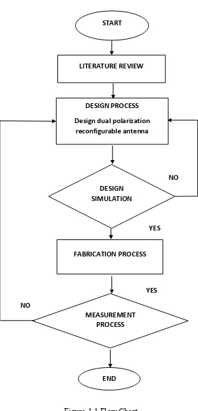
1.4 Project Methodology
6
[image:23.595.171.461.117.718.2]
Figure 1.1 Flow Chart START
LITERATURE REVIEW
DESIGN PROCESS Design dual polarization
reconfigurable antenna
DESIGN SIMULATION
FABRICATION PROCESS
MEASUREMENT PROCESS
END
YES NO
NO
CHAPTER II
LITERATURE REVIEW
The literature review is one of the developer’s methodologies to enhance the understanding of the field research for the developer. Besides that, literature reviews are made for the support of the arguments that are made during this research. Apart from that, the literature review is carried out in order to enable the reader to refer to this section if there is confusion and misunderstanding of some of the terms that are found throughout this research.