i
EVALUATION OF RADIO FREQUENCY INTERFERENCE (RFI) ON GLOBAL NAVIGATION SATELLITE SYSTEM (GNSS) SIGNALS
HASMADDY BIN WENTWES
This Report Is Submitted In Partial Fulfillment of Requirement for the Bachelor Degree of Electronic Engineering (Electronic Telecommunication) with Honours
Faculty of Electronic and Computer Engineering Universiti Teknikal Malaysia Melaka
v
Special dedicate:
vi
ACKNOWLEDGEMENT
Firstly, I would like to express my deepest thank to my supervisor, Dr. Ho Yih Hwa who had guided me a lot of task during two semesters. Besides that, thanks to the lectures and staffs from Faculty of Electronic and Computer Engineering for their cooperation, valuable information, suggestion and guidance during my research to complete this final year project.
Deepest thanks and appreciation to my family for their cooperation, encouragement, constructive suggestion and full of support for the report completion, from the beginning till the end. Thanks to all of my friends and everyone, those have been contributed by supporting my work and help myself during the final year project progress till it is fully completed.
vii
ABSTRACT
viii
ABSTRAK
ix
TABLE OF CONTENTS
CHAPTER TITLE PAGES
TITLE PAGE i
REPORT STATUS VERIFICATION FORM ii
DECLARATION iii
DEDICATION v
ACKNOWLEDGEMENT vi
ABSTRACT vii
ABSTRAK viii
TABLE OF CONTENTS ix
LIST OF TABLES xiii
LIST OF FIGURES xiv
LIST OG GRAPHS xvi
LIST OF ABBREVIATIONS xviii
I INTRODUCTION 1.1 INTRODUCTION 1
1.2 PROBLEM STATEMENTS 3
x
1.4 SCOPE OF THE PROJECT 3
II LITERATURE REVIEW
2.1 Global Navigation Satellite System (GNSS) 5
2.1.1 GPS and GLONASS 5
2.1.2 Satellite Propagation 6
2.1.3 How GPS Works 8
2.2 Radio Frequency Interference 11 2.3 Factors That Trigger GNSS Position Errors 13 2.4 The Effects of RFI on GNSS Receiver Output 16 2.5 Code Division Multiple Access (CDMA) 17
III PROJECT METHODOLOGIES
3.1 Project Methodology 19
3.1.1 Project Start 21
3.1.2 Literature Review 21
3.1.3 Equipment Preparations 21 3.1.4 Test Setup Analysis for Field Evaluations 24 3.1.5 Performing Test via Field Evaluations 25
3.1.6 Performance Analysis 25
xi
IV RESULTS AND DISCUSSIONS
4.1 Time Span Length and Test Circumstances 28 4.2 Absolute Signal Power and NMEA Data 29
4.3 GNSS Signal Measurements 31
4.3.1 Signal Power Interference of 20 dBm 31 4.3.1.1 Satellite PRN 26 31
4.3.1.2 Satellite PRN 22 32
4.3.1.3 Satellite PRN 18 32
4.3.1.4 Satellite PRN 14 32
4.3.1.5 Satellites Overview 33 4.3.2 Signal Power Interference of 10 dBm 34
4.3.2.1 Satellite PRN 26 34
4.3.2.2 Satellite PRN 22 34
4.3.2.3 Satellite PRN 18 35
4.3.2.4 Satellite PRN 14 35
4.3.2.5 Satellites Overview 35 4.3.3 Signal Power Interference of 0 dBm 37
4.3.3.1 Satellite PRN 26 37
4.3.3.2 Satellite PRN 08 37
4.3.3.3 Satellite PRN 18 38
4.3.3.4 Satellite PRN 14 38
4.3.3.5 Satellites Overview 38 4.3.4 Signal Power Interference of -10 dBm 40
4.3.4.1 Satellite PRN 26 40
4.3.4.2 Satellite PRN 22 40
xii
4.3.4.4 Satellite PRN 14 41
4.3.4.5 Satellites Overview 41 4.3.5 Overall Signal Interference in Each Satellite 42 4.3.6 Dilution of Precision (DOP) 44
4.4 Discussions and Analysis 46
4.4.1 GNSS Signals Strength 46
4.4.2 Dilution of Precision (DOP) 47
V CONCLUSION AND RECOMMENDATION
5.1 Conclusion 48
5.2 Recommendation 49
REFERENCES 50
xiii
LIST OF TABLES
NO TITLE PAGES
2.1 GNSS Frequencies and Bandwidths 11
3.1 Cost of Equipments 23
xiv
LIST OF FIGURES
NO TITLE PAGES
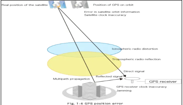
1.1 GNSS Position Errors 2
2.1 GNSS Satellite Overview 6
2.2 GNSS Satellite Propagation 8
2.3 Signals from 1 satellite 9
2.4 Signals from 2 satellites 9
2.5 Signals from 3 satellites 10
2.6 Signals from 4 satellites 10
2.7 The DOP Value either Smaller or Greater 14 2.8 Example of Stable GPS Positioning 15 2.9 Example of Unstable GPS Positioning 15 3.1 Flow Chart of Project Methodologies 19 3.2 Hittite HMC-T2000 700MHz-8GHz Signal Generator 22
3.3 Horn Antenna 22
xv
3.6 SMA-to-U.FL Connector Cable 23
3.7 Notebook 23
3.8 Block Diagram of setup analysis 24
3.9 Equipments setup analysis 24
3.10 Location of Field Measurement 25
xvi
LIST OF GRAPHS
NO TITLE PAGES
xviii
LIST OF ABBREVIATIONS
GNSS - Global Navigation Satellite System GPS - Global Positioning System
GLONASS - GLObal NAvigation Satellite System DOP - Dilution of Precision
1
CHAPTER I
INTRODUCTION
1.1 INTRODUCTION
2 The rapid growth in the development of Global Navigation Satellite Systems (GNSS) in current market, having penetrated various consumer products, such as cell phones, personal navigation devices (PNDs), cameras and assimilation with radio-frequency identification (RFID) tags are lead to degradation of GNSS signals. Thus, there is a need to characterize GPS signal degradation and quantify the effects of interference sources. GPS signal degradation typically occurs by signal masking caused by natural and man-made obstructions, ionospheric scintillation, Doppler shift, multipath, jamming, spurious satellite transmissions, and antenna effects. The impact of these interferences can result in total loss of tracking and possible tracking errors, depending on the severity of the effect and the receiver tracking characteristics. Tracking errors, especially if undetected by the receiver firmware, can result in large position errors. Partial loss of tracking results in geometry degradation, which in turn affects position accuracy. These error parameters can influence the accuracy of GNSS readings and in a number of cases it can disrupt GNSS signals as shown in Figure 1.1. This paper provides an overview of radio frequency interference (RFI) on the performance of GNSS signals strength and the Dilution of Precision (DOP) of the GNSS satellites via field evaluations.
3
1.2 PROBLEM STATEMENTS
Global navigation satellite system (GNSS) is powered by photocells, which are approximately 20200 km above the surface of earth. GNSS signal that reach the earth has very low power levels approximately -160 to -130 dBm, rendering them highly susceptible to jamming. Radio frequency Interference (RFI) has a significant influence on the tracking of GNSS satellite signals by a GNSS receiver. This can range from a degradation of the performance to a total prohibition of satellite signal acquisition and tracking. Any signals transmitted in or near the GNSS frequency bands will interfere with the reception of the GNSS signals.
So in this project, the performance of GNSS signals had been evaluated by an intentional jamming on the GNSS receiver. The test evaluation is conducted via field measurement by using GNSS receivers Arduino Compatible Development Board with GPS/GLONASS that receives real GNSS signals. The findings will be analysed using GNSS Viewer software.
1.3 OBJECTIVES
1) To observe the effect of radio frequency interference (RFI) on GNSS signals in real environment.
2) To study the signals strength and Dilution of Precision (DOP) of GNSS satellites before and after an intentional jamming.
1.4 SCOPE OF PROJECT
5
CHAPTER II
LITERATURE REVIEW
2.1 GLOBAL NAVIGATION SATELLITE SYSTEM (GNSS)
There are multiple constellations of GNSS satellites circling the earth. A constellation is essentially a precise arrangement of satellites, normally 20 to 30, in circles that have been intended to give a desired coverage, for instance, local or worldwide. GNSS satellites orbit well over the atmosphere, around 20,000 km over the world's surface. They are moving rapidly, a few kilometres for each second. There are two GNSS right now over the atmosphere which are GPS and GLONASS.
2.1.1 GPS AND GLONASS
6 1) Reduced signal acquisition time
2) Improved position and time accuracy
3) Reduction of problems caused by obstructions such as buildings and foliage
To determine a position in GPS-only mode, a receiver must track a minimum of four satellites. In combined GPS/GLONASS mode, the receiver must track five satellites, at least one of which must be a GLONASS satellite, so the receiver can determine the GPS/GLONASS time offset.
With the availability of combined GPS/GLONASS receivers, users have access to a satellite combined system with over 40 satellites. Performance in urban areas and other locations with restricted visibility improves as more satellites are accessible by the receiver [3].
2.1.2 SATELLITE PROPAGATION
[image:24.595.152.505.487.731.2]GNSS signals pass through the near-vacuum of space, then through the various layers of the atmosphere to the earth, as illustrated in Figure 2.1.