UNIVERSITI TEKNIKAL MALAYSIA MELAKA
THE EFFECT OF MATERIAL DISCONTINUITY ON THE
FLANGES OF AXIALLY COMPRESSED CYLINDER
This report submitted in accordance with requirement of the Universiti Teknikal Malaysia Melaka (UTeM) for the Bachelor Degree of Mechanical Engineering
Technology
(AUTOMOTIVE TECHNOLOGY) (Hons.)
by
LU KIAN HAP B071210514 920424-12-6515
UNIVERSITI TEKNIKAL MALAYSIA MELAKA
BORANG PENGESAHAN STATUS LAPORAN PROJEK SARJANA MUDA
TAJUK: The Effect of Material Discontinuity on the Flanges of Axially
Compressed Cylinder
SESI PENGAJIAN: 2015/2016 Semester 1
Saya LU KIAN HAP
mengaku membenarkan Laporan PSM ini disimpan di Perpustakaan Universiti Teknikal Malaysia Melaka (UTeM) dengan syarat-syarat kegunaan seperti berikut:
1. Laporan PSM adalah hak milik Universiti Teknikal Malaysia Melaka dan penulis. 2. Perpustakaan Universiti Teknikal Malaysia Melaka dibenarkan membuat salinan
untuk tujuan pengajian sahaja dengan izin penulis.
3. Perpustakaan dibenarkan membuat salinan laporan PSM ini sebagai bahan pertukaran antara institusi pengajian tinggi.
4. **Sila tandakan ( )
SULIT
TERHAD
TIDAK TERHAD
(Mengandungi maklumat yang berdarjah keselamatan atau kepentingan Malaysia sebagaimana yang termaktub dalam AKTA RAHSIA RASMI 1972)
(Mengandungi maklumat TERHAD yang telah ditentukan oleh organisasi/badan di mana penyelidikan dijalankan)
_____________________
Alamat Tetap:
4B 063, TAMAN PUTERI INDAH
BATU 4, JALAN LABUK, 90000
SANDAKAN, SABAH.
Disahkan oleh:
_______________________
Cop Rasmi:
iv
DECLARATION
I hereby, declared this report entitled “The Effect of Local Material Discontinuity on the Flanges of Axially Compressed Cylinder” is the results of my own research
except as cited in references.
Signature :………
Name : LU KIAN HAP
v
APPROVAL
This report is submitted to the Faculty of Engineering Technology of UTeM as a partial fulfilment of the requirements for the degree of Bachelor of Engineering Technology (Automotive Technology) (Hons.). The member of the supervisory is as follow:
vi
ABSTRACT
vii
ABSTRAK
viii
DEDICATIONS
ix
ACKNOWLEDGMENTS
Firstly, I would like to express my gratitude to my helpful supervisor Dr. Olawale Ifayefunmi from the Faculty of Engineering Technology, Universiti Teknikal Malaysia Melaka (UTeM), for his excellent supervision and encouragement on me to complete this final year project work.
Secondly, I would like to thank UTeM for the financial support throughout this project. Besides, I would also wish to express my gratitude towards the technicians, Encik Syafiq, Encik Fauzi and Encik Basri, who operate the water jet machine in the laboratory and helped me throughout this project. I would like to thank my colleagues who have worked with me and provide guidance and helped me to overcome the problems that I faced throughout the project.
x
TABLE OF CONTENTS
DECLARATION ... iv
APPROVAL ... v
ABSTRACT ... vi
ABSTRAK ... vii
DEDICATIONS ... viii
ACKNOWLEDGMENTS ... ix
TABLE OF CONTENTS ... x
LIST OF FIGURES ... xiii
LIST OF TABLE ... xv
LIST OF SYMBOLS AND ABBREVIATIONS ... xvi
CHAPTER 1 ... 1
1.0 Background ... 1
1.1 Problem Statement ... 2
1.2 Objectives ... 3
1.3 Scope ... 3
CHAPTER 2 ... 4
2.0 Introduction ... 4
2.1 Buckling of cylinder with initial geometric imperfection ... 4
2.2 Buckling of cylinder with non-uniform loading ... 6
xi
2.5 Summary of Literature Review ... 11
CHAPTER 3 ... 13
3.0 Research Design ... 13
3.1 Welded Cylinder without Flanges ... 14
3.2 Material selection ... 14
3.3 Manufacturing Process ... 15
3.3.1 Cutting process of flanges ... 15
3.3.2 The Gridding Process ... 18
3.3.3 Thickness measurement of cylinders and flanges ... 18
3.3.4 Height measurement of the cylinders ... 19
3.3.5 Diameter measurement of the cylinders ... 20
3.3.6 Welding process of the cylinders and flanges ... 21
3.4 Experimental Testing on Specimens ... 23
3.4.1 The setup of Instron Machine ... 23
3.4.2 The testing of Specimen ... 23
3.4.3 Collection of data ... 24
3.5 Numerical Analysis ... 26
3.5.1 Preparation of specimen drawing ... 26
3.5.2 Description of Numerical Modeling ... 26
CHAPTER 4 ... 28
4.0 Introduction ... 28
xii
4.1.1 Thickness measurement of cylindrical shell ... 28
4.1.2 Diameter measurement of cylindrical shell... 30
4.1.3 Height measurement of cylindrical shell... 33
4.2 Experimental results ... 34
4.3 Numerical result ... 40
CHAPTER 5 ... 46
5.0 Conclusion ... 46
5.1 Future Works ... 47
APPENDIX A ... 49
APPENDIX B ... 51
APPENDIX C ... 55
xiii
Figure 2.1: Measured flatness of the ring in Koiter (1963)... 7
Figure 2.2: Contact area of the cylinder and the loading surface in (Koiter, 1963). .... 7
Figure 2.3: Typical load-deflection curves for axially compressed mild steel cylinders. Two curves are shown for perfect cylinder and for cylinder with varying axial length (Blachut, 2010). ... 8
Figure 2.4: Variable axial length at the top of cylinder (Blachut, 2015). ... 9
Figure 2.5: Computational models of a cylinder shell with (A) a circumferential crack and (B) an axial crack. ... 10
Figure 3.1: Workflow of the project. ... 13
Figure 3.2: The design of cylinder without flanges. ... 14
Figure 3.3: Water jet cutting machine. ... 15
Figure 3.4: Metal plate is placed in the water jet machine... 16
Figure 3.5: The cutting process in progress. ... 16
Figure 3.6: The remaining metal plate. ... 17
Figure 3.7: Photograph of a cut out flange. ... 17
Figure 3.8: The gridding process. ... 18
Figure 3.9: Thickness measurement of cylinder. ... 19
Figure 3.10: Thickness measurement of flange. ... 19
Figure 3.11: Height measurement of cylinder. ... 20
Figure 3.12: Outer diameter measurement. ... 20
Figure 3.13: Inner diameter measurement. ... 21
Figure 3.14: The process of MIG welding. ... 21
Figure 3.15: The bottom part is fully welded. ... 22
Figure 3.16: The upper part is not fully welded. ... 22
Figure 3.17: The Instron Machine. ... 23
Figure 3.18: Axial compression test on 0% crack specimen. ... 24
Figure 3.19: The sample result of the axial compression test. ... 25
Figure 4.1: The intersection point for thickness measurement. ... 29
Figure 4.2: Distance between 2 opposite points at the circumference of the cylindrical shell as diameter. ... 30
Figure 4.3: Top view of the cylindrical shell with points labelled on the circumference. ... 31
Figure 4.4: Measurement of height in vertical direction. ... 33
Figure 4.5: The line-up of specimens after compressive test. ... 34
Figure 4.6: The appearance of specimen after compressive test. ... 35
Figure 4.7: Plot of compressive load against compressive extension (Specimen 10). ... 36
xiv
xv
Table 2.1: Summary of literature review. ... 12
Table 3.1: Measured geometry of specimens. ... 27
Table 3.2: Nominal geometry of specimens. ... 27
Table 4.1: Average thickness of cylinder of each specimen. ... 29
Table 4.2: Summary of diameter measurement of all specimens. ... 32
Table 4.3: Summary of height measurement of all the specimens. ... 33
xvi
LIST OF SYMBOLS AND ABBREVIATIONS
kN = kilo Newton
m = meter
mm = milimeter
r = radius
t = thickness
1
CHAPTER 1
INTRODUCTION
1.0 Background
Since decades ago, cylindrical structures are widely used in the field of civil, mechanical, architectural, aeronautical and marine engineering (Farshad, 1992). One of the main failure criteria when designing these structures is buckling (Budiansky and Hutchinson, 1972). Over the years, it has been argued that the presence of defects, such as cracks, may severely compromise the buckling behaviour of these structures and thereby jeopardize their structural integrity (El Naschie, 1974). The focus of this study is on the effect of materials discontinuity on the flanges of axially compressed cylinder. When the cylindrical shell structures are applied in some applications, such as pipelines, buildings support and cooling towers, they will be subjected to different kind of loads such as axial compression, external pressure, internal pressure, torsion etc (Blachut, 2014). In this condition, structural designer have to pay great effort on their design to overcome buckling effect that can cause failure to the structure. The failure of the structures has brought up a lot of research in this field about the mechanical behaviour of the thin shell structure under load. The understanding towards the factors contributing to buckling problem is necessary in order to carry out the buckling analysis successfully. In most of the situation, cylindrical shell structures are subjected to compressive forces in the direction of cylinder axis, either uniform or varying throughout the cylinder. The buckling strength of a thin cylindrical shell under axial compression is particularly sensitive to imperfections such as crack in the shell (Remmers, 2006).
2
numerical approach. Investigation has been done for this research to figure out the buckling behaviour of the welded cylindrical shells with material discontinuities of the hoop length on the flanges, when subjected to axial compression.
1.1 Problem Statement
It is undeniable that the presence of crack on any structure will affect or reduce the strength of the structure. In some cases, it might cause serious failure of the structure, the same goes to the cylindrical structure. According to (Remmers, 2006), the presence of crack will affect the buckling behaviour of structural components resulting in failure of the structures especially cylindrical shell structures. Defects could lead to large localized deformations such as local buckling or plastic deformation, which can alter the structure’s load carrying capacity or function (Javidruzi et al, 2004). Presence of defects, such as cracks, may severely compromise their buckling behaviour and jeopardize the structural integrity (Hutchinson et al, 1972). In general, the buckling behaviour of the cylindrical shells under torsional loading is less sensitive to the presence of a crack than that of a similar axially compressed cylindrical shell (Estekanchi and Vafai, 1999).
3
Based on the problem statement and background above, there are two objectives for this research:
i. To manufacture cylinders with material discontinuity introduced on its flange during welding process.
ii. To monitor and study the effect of material discontinuity on the flanges of axially compressed cylinder on the load carrying capacity.
1.3 Scope
The aim for this project is to investigate the effect of local material discontinuity of the percentage of the hoop length on the flanges of the welded cylindrical shells subjected to axial compression under experimental and numerical analysis. The chosen material for the cylindrical structures and the flanges is mild steel. The nominal thickness of mild steel plates for cylinders is 2 mm and 10 mm for the flanges.
4
CHAPTER 2
LITERATURE REVIEW
2.0 Introduction
Thin-walled shell structures have been widely used in pipelines, aerospace and marine structures, large dams, shell roofs, liquid-retaining structures and cooling towers (Farshad, 1992). Thin-walled structures are usually used to support load in most engineering applications. Anyway, there is a problem that needs to be considered, that is failure that occurs when they are subjected to high load. In shell structures, the load carrying capacity is usually limited and governed by the buckling phenomena. Failure of cylindrical structures can happen in any situation. There are various types of imperfections that can occur on a cylindrical structure which can cause failure on it. The imperfections are (i) initial geometric imperfection, (ii) non-uniform loading, (iii) non-non-uniform axial length, and (iv) crack on cylindrical structures. The following section presents extensive literature review of the four imperfection types mentioned. This is done in order to have an indepth knowledge of what have been done experimentally in this area of study, thereby identifying the gap in knowledge.
2.1 Buckling of cylinder with initial geometric imperfection
One of the most commonly considered type of imperfection is the initial geometric imperfection, i.e, axisymmetric dimple, eigen-mode imperfection, geometric dimple, single perturbation load and single stress-free dimple.
5
shells. It is found that the buckling behaviour of imperfection sensitive shells under axial loading is commonly affected by their initial geometric imperfections which resulted from the manufacturing procedure (Papadopoulos and Iglesis, 2007).
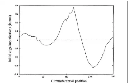
The buckling strength of circular cylindrical shells are sensitive to the form and amplitude of very minor deviations of geometry (geometric imperfections) from the ideal shape, meaning that measurement and characterization of the extent to which geometric imperfections reduces the load bearing capacity is of engineering significance (Fatemi et al, 2013).
According to (Linus et al, 2015), the presence of geometrical imperfections is found to have a high degrading effect even though the perfect shell structure are within the limits of manufacturing tolerance. In order to account for imperfect shell structures within the preliminary design phase, it is common practice to apply knock down factor, which is the ratio of experimentally determined buckling loads to theoretical buckling loads of the geometrically perfect shell structure. Besides, (Friedrich et al, 2015) also states that the rotational-symmetric imperfection is identified to be more critical than the non-rotational-symmetric imperfections. Consequently, this type of imperfection gains particular importance for the preliminary design of shell structures.
It was reported that both analytical results and experimental results are deviated widely from each other due to inevitable differences called imperfections which are presented in the real structure from the perfect structure (Rathinam and Prabu, 2015). According to (Victor et al, 2014), initial geometrical imperfections are identified as the major source of discrepancy between analytical and experimental results. An investigation about the applicability of the Single Perturbation Load Approach (SPLA) on sandwich shells has been done and it is compared with four other imperfection patterns.
6
engineers should acquire sufficient knowledge on the physical behaviours of shell buckling in order to prevent unexpected catastrophic failure of structures of which thin cylindrical shells are essential components.
2.2 Buckling of cylinder with non-uniform loading
Additional studies showed that geometric imperfections is not the only reason of the discrepancy between theory and experiments, and that the effect of thickness variability, material imperfections, imperfect boundary conditions as well as the non-uniformity of the applied axial load proved to be equally important leading to a further reduction of the predicted buckling loads (Arbocz and Babcock, 1969; Hoff and Soong, 1969; Libai and Durban, 1977; Greenberg and Stavsky, 1995; Arbocz, 2000; Arbocz and Starnes, 2002).
Non-uniformity of the axial loading as well as the uncertainty on the boundary conditions, were treated in the past using mainly the asymptotic theory without taking into account the combined effect of more than one sources of imperfections (Arbocz and Babcock, 1969; Hoff and Soong, 1969; Libai and Durban, 1977; Greenberg and Stavsky, 1995; Arbocz, 2000).
The approach used for modelling the non-uniformity of axial loading was essentially equivalent to that of modelling the geometric boundary imperfections in the sense that both of them resulted in introducing a non-uniform axial load pattern acting on the cylinders’ edges (Papadopoulos and Iglesis, 2007). This equivalence was made more evident in (Arbocz, 2000) where imperfections of the boundary conditions were modelled as in-plane geometric edge imperfections and were combined with the initial out-of-plane geometric imperfections in a non-linear finite element analysis using a two-step analysis procedure.
7
Figure 2.1: Measured flatness of the ring in Koiter (1963).
Figure 2.2: Contact area of the cylinder and the loading surface in (Koiter, 1963).
2.3 Buckling of cylinder with non-uniform axial length
8
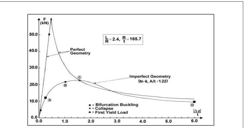
2010), these local effects at the imperfect end of the cylinder can propagate along the shell’s length and cause collapse. An experiment of a rigid plate and cylinder with various boundaries at the top edge has been carried out. As the rigid plate moves further down to the contact area between the plate and the cylinder changes. As a result of axial compression, the cylinder’s load carrying capacity can be limited either by collapse or by bifurcation buckling (Blachut, 2010). The result is shown in Figure 2.3.
Figure 2.3: Typical load-deflection curves for axially compressed mild steel cylinders. Two curves are shown for perfect cylinder and for cylinder with varying
axial length (Blachut, 2010).
9
Figure 2.4: Variable axial length at the top of cylinder (Blachut, 2015).
2.4 Buckling of cylinder with crack
Material discontinuity is also known as cracks or defects in thin-walled shell structures which can cause severe and catastrophic failure of the structural member. The post-buckling analysis of cracked plates and shells indicated that the buckling deformation could cause a considerable amplification of the stress intensity around the crack tip. Presence of defects such as cracks, which may develop during manufacturing or service life of composite cylindrical shells, could severely affect the buckling behavior of structures not only by reducing their load carrying capacity but also by introducing local buckling at the crack region (Vaziri and Estekanchi, 2006). The presence of cracks in a shell structure can play the role of geometrical imperfection and thus reduce the load carrying capacity of shell structure (Vafai and Estekanchi, 1996). (El Naschie, 1974), considered the buckling problem of a cracked shell for the first time, he found that the buckling load of circular cylindrical shells with a complete circumferential crack is shown to be half of that of the perfect cylinder.