UNIVERSITI TEKNIKAL MALAYSIA MELAKA
ENHANCEMENT OF THE NEW DRYING APPLICATION
This report submitted in accordance with requirement of the Universiti Teknikal Malaysia Melaka (UTeM) for the Bachelor Degree of Engineering Technology
(Bachelor of Mechanical Engineering Technology (Refrigeration and Air-Conditioning Systems) (Hons.)
by
AHMAD RIFDI BIN RAZALI
B071210549
910211-14-5967
UNIVERSITI TEKNIKAL MALAYSIA MELAKA
BORANG PENGESAHAN STATUS LAPORAN PROJEK SARJANA MUDA
TAJUK: “ENHANCEMENT OF THE NEW DRYING”
SESI PENGAJIAN: 2015/16 SEMESTER 1
Saya: AHMAD RIFDI BIN RAZALI
mengaku membenarkan Laporan PSM ini disimpan di Perpustakaan Universiti Teknikal Malaysia Melaka (UTeM) dengan syarat-syarat kegunaan seperti berikut:
1. Laporan PSM adalah hak milik Universiti Teknikal Malaysia Melaka dan penulis. 2. Perpustakaan Universiti Teknikal Malaysia Melaka dibenarkan membuat salinan
untuk tujuan pengajian sahaja dengan izin penulis.
3. Perpustakaan dibenarkan membuat salinan laporan PSM ini sebagai bahan pertukaran antara institusi pengajian tinggi. atau kepentingan Malaysia sebagaimana yang termaktub dalam AKTA RAHSIA RASMI 1972)
(Mengandungi maklumat TERHAD yang telah ditentukan oleh organisasi/badan di mana penyelidikan dijalankan)
( )
FAKULTI TEKNOLOGI KEJURUTERAAN
PENGKELASAN LAPORAN PSM SEBAGAI SULIT/TERHAD LAPORAN PROJEK SARJANA MUDA TEKNOLOGI KEJURUTERAAN MEKANIKAL (Bachelor of Mechanical Engineering Technology (Refrigeration and Air-Conditioning Systems) (Hons.). AHMAD RIFDI BIN RAZALI
Sukacita dimaklumkan bahawa Laporan PSM yang tersebut di atas bertajuk
“ENHANCEMENT OF THE NEW DRYING APPLICATION” mohon dikelaskan sebagai *SULIT / TERHAD untuk tempoh LIMA (5) tahun dari tarikh surat ini.
2. Hal ini adalah kerana IANYA MERUPAKAN PROJEK YANG DITAJA OLEH
SYARIKAT LUAR DAN HASIL KAJIANNYA ADALAH SULIT.
Sekian dimaklumkan. Terima kasih.
Yang benar,
________________
Tandatangan dan Cop Penyelia
* Potong yang tidak berkenaan
NOTA: BORANG INI HANYA DIISI JIKA DIKLASIFIKASIKAN SEBAGAI SULIT DAN
TERHAD. JIKA LAPORAN DIKELASKAN SEBAGAI TIDAK TERHAD, MAKA
iii
DECLARATION
I hereby, declared this report entitled “ENHANCEMENT OF THE NEW DRYING APPLICATION” is the results of my own research except as cited in references.
Signature :………
iv
APPROVAL
This report is submitted to the Faculty of Engineering Technology of UTeM as a partial fulfilment of the requirements for the degree of Bachelor of Engineering Technology (Bachelor of Mechanical Engineering Technology (Refrigeration and Air-Conditioning Systems) (Hons.). The member of the supervisory is as follow:
v
ABSTRAK
Kajian ini melibatkan penambahbaikan dalam proses pengeringan. Kebanyakan pengering konvensional yang asal menggunakan elektrik untuk menjana haba, penggunaan elektrik akan memberi kesan terhadap pengunaan tenaga. Pengering konvensional yang asal mengambil lebih banyak masa untuk mengeringkan pakaian, ia membuang masa. Masalah lain yang mungkin pengguna hadapi adalah bahagian-bahagian di dalam mesin pengering mengalami kerosakan yang membuat mesin itu tidak berfungsi. Dalam kajian ini, beberapa sasaran telah ditetapkan untuk memastikan bahawa kajian semasa tidak menyeleweng dari sasaran asal. Kajian utama projek semasa adalah, untuk mempercepatkan kadar pengeringan dan menjimatkan masa dengan menggunakan beberapa penebat dan juga untuk memeriksa jumlah haba yang disediakan dalam kabinet pengering yang melibatkan sumber haba ditutup. Reka bentuk kabinet logam adalah penting untuk mencapai objektif kajian semasa dan projek ini akan berakhir dengan kerja eksperimen ini. Kabinet logam akan dibina berdasarkan saiz sebenar almari yang boleh didapati di pasaran. Dimensi almari logam adalah 2 m (H) × 1 m (L) × 0.5 m (W), dan juga mempunyai beberapa lubang aliran udara untuk menyediakan aliran udara di dalam kabinet logam. Parameter yang paling penting untuk diukur dalam almari adalah suhu, dan perlu mengambil kira tahap suhu yang memberi suhu tertinggi didalam kabinet tersebut. Suhu tertinggi didalam kabinet adalah pada tahap satu dan tahap dua dengan 1.2 m dan 1.5 m dengan suhu tertinggi adalah 62.1°C dan 62.3°C. Objektif kedua eksperimen ini apabila menggunakan grill sebagai penghalang pada kawasan haba sumber, suhu tertinggi di dalam kabinet di peringkat tiga dan tahap satu memberi suhu tertinggi ialah 60.8 ° C dan 61.4 ° C. Ia dijangka bahawa penggunaan penebat untuk mempercepatkan kadar pengeringan di dalam kabinet logam adalah dicapai. Projek semasa bersedia untuk menyumbang kepada pengguna bagi tujuan pengeringan dengan beberapa kebaikan seperti mas untuk pengeringan lebih singkat, penjimatan kos dalam jangka masa yang panjang dan juga pakaian boleh terus dipakai setelah proses pengeringan selesai.
vi
ABSTRACT
vii
DEDICATIONS
To my beloved parents Asmah binti Ismail and Razali ABD Ghani and to my beloved siblings, who always love, pray for my success and always support me. Also I like to dedicated all my hard work and efforts on finishing this project to my supervisor, Dr Ahmed Salem Seed Bin Ghooth, for supporting me through this project
Lastly, I like to dedicate this project to my entire classmate and friends that always support and help to contribute some ideas and give some help on completing this project.
viii
ACKNOWLEDGMENTS
Firstly I would like to say Alhamdulillah and thanks to Allah for providing me strengths to complete the final year project in order to get my first degree in my study. This project is impossible to be complete in time without supports from people around me. I would like to thanks my family especially my parents, that always keep supporting and always gave advice to me and always pray for my health and successful in life.
I would like to express my appreciation to my supervisor, Dr Ahmed Salem Seed Bin Ghooth, because of his commitment to contribute his time and always keep on guiding me to complete my project. His knowledge helps me a lot to finish this final year project and without any help from him, it would be difficult for to complete this project.
Also thanks to my faculty, Faculty of Engineering Technology (FTK) which provide most of the equipment and tools that impossible for student to have it by our own to complete my final year project. Also thanks to all staff that support and guide during conducting my final project experiment.
ix
TABLE OF CONTENT
DECLARATION……….iii
APPROVAL………iv
ABSTRAK..………...v
ABSTRACT..………...vi
DEDICATION………...vii
ACKNOWLEDGMENTS………...viii
TABLE OF CONTENTS………ix
LIST OF FIGURE……….xiii
LIST OF TABLE………...xv
LIST OF SYMBOLS AND ABBREVIATIONS………..xvi
CHAPTER 1: INTRODUCTION 1.0 Background.………...1
1.1 Problem statement………...3
1.2 Project objective………..3
1.3 Work scope……….3
1.4 Organization of the thesis………...4
CHAPTER 2: LITERATURE REVIEW 2.0 Introduction for Drying Process………...5
x
2.1.1Air vented tumbler dryer………...7
2.1.2 Condensing Tumbler Dryer………...8
2.1.3 Heat Pump Tumble Dryers………...9
2.1.4 Gas Tumble Dryers………...10
2.2 Types of Insulation………...10
2.2.1 Blanket: batt and roll insulation……….11
2.2.2 Rigid fiber board insulation………...11
2.2.3 Foamboard or rigid foam...11
2.2.4 Loose - Fill And Blown In – Insulation………11
2.2.5 Radiant barriers and reflective insulation systems………12
2.3 Co2 as Working Fluid for Heat Pump Dryers………..12
2.4 Related Work………...13
CHAPTER 3: METHODOLOGY 3.0 Introduction………...16
3.1 Design and preparation of the project……….16
3.1.1 Materials and equipments………....16
3.1.2 Prototype preparation………...24
3.1.3 Preparation body of the metallic cupboard………...24
3.1.4 Apparatus and Material Assembly………...25
3.2 Experimental works………...25
3.2.1 Experiment setup………...25
xi
3.2.3 Experimental work 1...………...26
3.2.4 Experimental work 2…...35
3.2.5 Experimental work 3……….……...36
3.3 Flow chart of the experiment………...38
3.4 Procedure on making the metallic cupboard………....39
CHAPTER 4: RESULT AND DISCUSSION 4.0 Introduction………...41
4.1 Experiment 1………...41
Case 1 With closed all air flow…...41
Case 2 (a) open air flow at the side of cupboard body within the level 5………...43
Case 2 (b) open air flow under the body of the cupboard...44
Case 3 with open air flow all air flow…...45
4.2 Experiment 2………...46
Case 1 Insulated Cupboard………...47
4.3 Experiment 3………...48
Case 1 Insulated Cupboard with a Plate of Galvanized Steel Cover on Heat Source Area………...48
Case 2 Insulated Cupboards with a Grill Cover on Heat Source Area...50
4.4 Comparison between Insulated Cupboard and Without Insulated Cupboard………...51
xii
CHAPTER 5: CONCLUSION AND RECOMMENDATION
5.0 Introductions………...57
5.1 Conclusion of the current study………...57
5.1.1 Accelerate the Drying Rate and Save Time by Using Some Insulation...57
5.1.2 Check amount of heat provided inside the cupboard in case of Covering heat source………...58
5.2 Future Work………...58
Type of insulation use………...58
Design of the cupboard…………...59
Appendix………...60
xiii
LIST OF FIGURES
Figure 2.1: Schematics of a conventional air-vented dryer. (Fabric-drying process in
domestic dryers) ………...7
Figure 2.2: Schematic of a conventional condenser tumbler dryer...8
Figure 2.3: Cross section area for heat pump tumbler dryer...9
Figure 2.4: Gas tumbler dryer...10
Figure 3.1: Galvanized steel...17
Figure 3.2: Insulation foam type...17
Figure 3.3: Clothes cotton and jeans...18
Figure 3.4 (a): Small gas stove...19
Figure 3.4 (b): Propane gas...19
Figure 3.5: 2 Channel thermocouples...19
Figure 3.6: GL 220 data logger...20
Figure 3.7: Small scale weight balanced...21
Figure 3.8: Bending machine...21
Figure 3.9: Cutting machine...22
Figure 3.10: Cordless drill...22
Figure 3.11: Rivet tools...23
Figure 3.12: Grind machine...23
Figure 3.13: Galvanized metallic cardboard prototype...24
Figure 3.14: With no air flow provided...27
Figure 3.15: With open air flow within level five...29
Figure 3.16: With open air flow under the cupboard...31
xiv
Figure 3.18: Cupboard with insulation...35 Figure 3.19: Optimization cases...36 Figure 4.1: Temperature against gas flow rate with close all air flow...41 Figure 4.2: Temperatures against gas flow rate with open air flow within the
level 5...43 Figure 4.3: Temperature against gas flow rate with open air flow under the body of cupboard...44 Figure 4.4: Temperature against gas flow rates with open all air flow...45 Figure 4.5: Temperatures against gas flow rate inside the insulated cupboard...47 Figure 4.6 Temperature against gas flow rate with insulated Cupboards with a Plate of Galvanized Steel Cover on Heat Source Area...48 Figure 4.7 Temperature against gas flow rate Insulated Cupboards with a Grill
on Heat Source area...50 Figure 4.8 Percentage differences against gas flow rate with and without
xv
LIST OF TABLE
Table 3.1: Temperature in different levels...27
Table 3.2: Temperature in different levels...29
Table 3.3: Temperature in different levels...31
Table 3.4:Temperature in different levels...33
Table 3.5: Temperature in different levels...35
Table 3.6: Temperature in different levels...36
Table 3.7: Temperature in different levels...37
Table 3.8: Temperature in different levels...37
Table 4.1: Temperature different at different level...51
Table 4.2: Percentage at different level...52
Table 4.3: Temperature different at different level...54
xvi
LIST OF SYMBOLS AND ABBREVIATIONS
°C Degree celcius
KJ Kilo joule
KG kilogram
s second
K Kelvin
TS Temperature surface
Tφ Temperature surrounding
% Percentages
ṁ Gas Mass flow rate
(T 2- T1) Temperature difference
h2 - h1 Enthalpy difference
Wi Initial weight for propane gas
Wo Final weight for propane gas
Cp Specific heat
Ti Initial temperature
Tavg Average temperature
h Heat transfer coefficient
1
In this chapter introduction the most important topics which contain the project are briefing background, problem statement, objectives, scope of the project and thesis organization of overall chapters and all of these topics are presented with details within this chapter.
1.0 Background
In 1874 the first hand driven washing machine for home use was design by William Blackstone, from that time the technology begins to expand, the combination of the new invention has produced a washing machine and dryer to help to complete the task of laundry. Despite the basic design of the dryer has not changed much in people washed, rinsed and wrung out clothes by hand and hung them over rocks, tree branches or later clotheslines to dry in the open sun areas. The first dryer invented was a simple wooden rack to hang clothes near a fire to dry. The first mention of a modern type dryer appeared in the 1800s when a Frenchman by the name of Pochon invented a vented-barrel-shaped drum called a ventilator to dry clothes. Clothes were placed inside the drum and the drum was turned by hand over an open fire. It was not a very reliable method or machine, but opened the doors for future designs. Though there seems to be some controversy over the patent description of George T
2
Sampson's dryer, he is credited with a ventilator dryer using a stove as its heat source. By 1915, the electric clothes dryer was introduced but it was not until the Hamilton Manufacturing company produced the first automatic dryer in 1938 that the use of the dryer started to become known. (http://esporta.ca/) From 1938 through the 1960s, the cost of owning a dryer remained out of reach for most people with a dryer in the 1950s costing the equivalent of $1600 in today's money. New technologies, production methods, and lower costs put the dryer in more homes by the late 1990s. As technology continues to open the doors to the use of cost efficient designs, the use of new technology is changing the dryer, as we now know it. Using solar dryers, vent-less dryers, also known as compression or heap pump dryers, and dryers that make use of microwave technology may soon make the tumble dryer simply another part of history. The dryer that has not changed much in design or function in over two hundred years is going through rapid change in both design and energy use. These changes will provide a more efficient use of time and resources.
This study is representing on enhancement of the new drying application process. Mostly original conventional drying application using electric to generate heat, use of electricity will give an effect on energy consumption and also consume more cost to consumer. The original drying application also may take more time to dry the clothes, it waste time on waiting the clothes to dry. Other problem that consumer may face on modern drying application is parts in the drying machine might broken or malfunction that make the machine did not function.
The current project aimed to improvise the wardrobe which was done and based on the original idea of drying application to accelerate the drying rate and also to avoided odor coming inside the metallic cupboard cause from using the gas stove by adding some fans to make a good ventilation inside the metallic cupboard.
3 1.1 Problem Statement
Limitations associated with original design included hotness of the Galvanized metallic cupboard outside surfaces, more heat loss, and the occurrence of adverse effect if the clothes fall on the open fire. Avoiding heat loss in all sides of the metallic cupboard and find the appropriate manner to cover the heat of source area with supplying the same amount of heat is the challenge for the current project.
1.2 Project Objectives
In this study, some targets have been set to ensure that the current study is not diverge from the original target when investigations are conducted. The main objectives for the current project are:
1. To accelerate the drying rate and save time by using some insulation.
2. To check the amount of heat provided inside the drying cabinet in case of covering heat source.
1.3 Work Scope
4 1.4 Organization Of The Thesis
5
In this chapter there are several sub topics described, such as introduction for drying process, types of tumbler dryer, CO2 as a working fluid for heat pump dryers,
humidity and also related work.
2.0 Introduction For Drying Process
Drying is a process to remove water from a substance and it’s one of the most widely used operating processes in daily life which is undeniably as an energy-intensive operation (Ah Bing Ng, and Shiming Deng 2008). This process occurs when a wet is involved with thermal drying, it will involve with two process at the same time, first when heat energy is transferd from surrounding environment to evaporate the surface moisture and second, transfer of internal moisture to the surface of the solid and its subsequent evaporation due to the first process (Handbook of Industrial Drying fourth edirtion, Arun S. Mujumdar 2014). Rate of drying is accomplish by determined the rate of the two process occurs (Handbook of Industrial Drying). Heat transfer energy occurs from wet surrounding that result from a convection, conduction, radiation or in others cases, result of a combination of these effects. Clothes dryer is one of the common dryers was produced by industries for people to use either for commercial or residential use. In the past few years, a lot of effort has been made by researcher to ensure that the energy efficient dryer can decrease the total cost and help in contributing on the environment preservation such as replacing use of electricity with hot water, it’s because to use electricity for a small appliance such as clothes dryer is such a loss and not efficient in term of energy use (Ah Bing Ng, and Shiming Deng 2008) ,( Pradeep Bansal et al 2010). Mostly use of clothes
6
dryer depend on the electricity to work, by heat the heating element the hot air supply inside the clothes dryer. For conventional type of clothes dryer there are two categories, air vented dryer and condensing dryer. Conventional dryer operates with same operation where supply power is heating the heating element and with the help of outside air, the hot air enters the clothes dryer and drying process is happend. Tumbler dryer in the market mostly are not very efficient. It can be classified by the rating, which mostly the rating for tumbler dryer is lower compared with the given rating from the manufacturer. (http://www.nwu.ac.za). As stated previously, in order to operate correctly the dryer needs a constant flow of air. The airflow for the tumbler dryer was important; to make sure the tumbler dryer can be operate efficiently without any losses. the important of air flow for tumbler dryer is like this, if the air flow is not there the tumbler dryer will not function , if in tumbler dryer didn’t have enough airflow the tumbler dryer will not work correctly. A lot of experiments and researches on conventional tumbler dryer that popular among consumer which is air vented dryer, condensing dryer, heat pump and gas dryer that has been done. A lot of idea that come from research to improve and do an enhancement on all this type of tumbler dryer, some said using heat exchanger it can improve the performance tumbler dryer, some propose an idea by makeing an air pump cycle for this dry also have and suggestion from some researcher that propose by improve the drum seals to reduce the air leakage. There is a considerable leakage of warm air from the recirculation air system in the tumble dryer, which indicates an energy loss from the system. According to the Swedish Consumer Agency 1996:3, it is desirable to decrease the energy consumption by 12% during the drying of a standard 5.0kg load of dry cotton containing 3.5kg of water to reach an energy efficiency classification B for the machine.
2.1 Types Of Tumbler Dryer
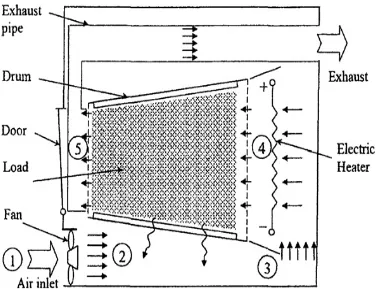
7 2.1.1 Air vented tumbler dryer
The figure below show a schematic of conventional air vented dryer, and some parts inside the air vented dryer.
Figure 2.1. Schematics of a conventional air-vented dryer. (Fabric-drying process in domestic dryers)