ISSN: 1693-6930
accredited by DGHE (DIKTI), Decree No: 51/Dikti/Kep/2010 25
Five-Level Common-Emitter Inverter Using
Reverse-Blocking IGBTs
Suroso*1, Toshihiko Noguchi2 1
Department of Electrical Engineering, Jenderal Soedirman University, Indonesia 2
Department of Electrical and Electronics Engineering, Shizuoka University, Japan e-mail: [email protected], [email protected]
Abstrak
Dalam operasi penyaklaran frekuensi tinggi untuk inverter sumber-arus (CSI), cara konvensional untuk mendapatkan saklar daya satu arah adalah dengan menghubungkan dioda diskrit secara seri dengan saklar daya kecepatan tinggi, seperti power MOSFETs atau IGBTs. Namun, dioda diskrit ini menyebabkan rugi-rugi tambahan pada konverter daya. Makalah ini menyajikan hasil pengujian eksperimen CSI emitor-bersama lima-level dengan penyaklaran frekuensi tinggi menggunakan saklar daya satu arah yang sedang berkembang saat ini, yaitu pemblokingan balik (RB)-IGBTs. Kinerja antara saklar daya satu arah power MOSFETs yang terhubung seri dengan dioda diskrit, dan RB-IGBTs yang tidak menggunakan dioda diskrit juga di uji. Hasil pengujian menunjukkan bahwa dengan menggunakan RB-IGBTs, efisiensi dari konverter daya meningkat jika dibandingkan dengan menggunakan power MOSFET dan dioda diskrit. Namun arus pemulihan balik untuk RB-IGBT ini lebih lambat dibandingkan dioda pemulihan-cepat diskret yang terhubung seri dengan MOSFET daya.
Kata kunci: common-emitter, CSI, frekuensi tinggi, inverter, multilevel
Abstract
In a high switching frequency operation of current-source inverter (CSI), a conventional way to obtain unidirectional power switches is by connecting discrete diodes in series with the high speed power switches, i.e. power MOSFETs or IGBTs. However, these discrete diodes will cause extra losses to the power converter. This paper presents experimental test results of high switching frequency five-level common-emitter CSI using the emerging unidirectional power switches, i.e. reverse blocking (RB)-IGBTs. Experimental tests were also conducted to compare the performance between power MOSFETs in series with the discrete diodes, and the RB-IGBTs having inherent reverse blocking capability. The results show that using RB-IGBTs, the efficiency of the power converter increase. However, it is also confirmed that the recently available RB-IGBTs have slow reverse recovery current than the discrete fast-recovery diodes connected in series with power MOSFETs.
Keywords: common-emitter, CSI, high frequency, inverter, multilevel
1. Introduction
waveforms, lower dv/dt or lower di/dt, and resulting in reduction of voltage or current stress in the switching devices, reduction of EMI noise and reduction of the output filter size [4], [5]. The CSI features simple converter topology, motor-friendly waveforms, and reliable short-circuit protection.
Many researchers and engineers have only focused on the multilevel VSI rather than its counterpart, multilevel CSI. Hence, a plenty of multilevel VSI topologies have been presented, but only a few topologies of multilevel CSI can be found in the literatures. As a result, the multilevel VSIs are more widely used than the multilevel CSIs topology. This condition is also caused by some drawbacks in multilevel CSI topologies such as bulky inductors required to obtain smooth DC current sources and the intermediate level currents [6]-[8]. Moreover, even symmetric thyristors having reverse-blocking capability can be used in CSI, however these devices are hard to operate in high switching frequency operation [9]. Thus, in higher switching frequency application, fast recovery discrete diodes are usually connected in series with the power switches, e.g. IGBTs and MOSFETs, to obtain reverse blocking capability. The series diodes often degrade the overall efficiency of the CSIs. However, the series diode will be unnecessary because new IGBTs with reverse-blocking capability (RB-IGBTs) are emerging [10]. Currently, some low and medium power RB-IGBTs are already available in market such as IXRH 50N120 and IXRP 15N120 from IXYS. These RB-IGBTs are very suitable for current-source inverter. It can eliminate the voltage drop caused by the discrete diodes connected in series with the power switches of the conventional unidirectional power switches. This paper presents experimental test results of the new five-level common-emitter CSI operates in high switching frequency operation using RB-IGBTs. The results are also compared to the power case of CSI, because filter capacitors are connected in parallel with power load, unidirectional power switches are indispensable in order to prevent short-circuit condition of the filter capacitor. Figure 1 shows various configurations of unidirectional current power switches for high switching frequency application. Figure 1(a) and (b) present unidirectional power switches obtained using power MOSFETs or IGBTs connected in series with discrete diodes. The extra loss caused by the discrete diodes is the main drawback of these power switch configurations. Currently, some power semiconductor companies have been developing unidirectional power switches with inherent reverse blocking capability, i.e. RB-IGBTs as shown in Figure 1(c). This RB-IGBT does not need discrete diode; hence it can reduce the component number, and eliminate the loss caused by the discrete diodes.
(a) (b) (c)
Figure 1. Various configurations of high speed unidirectional power switches: (a) power MOSFET with diode, (b) IGBT with diode, and (c) RB-IGBT
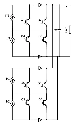
main feature of this circuit is that all of the power switches (Q1, Q2, Q3 and Q4) are connected at a common-emitter line. A higher level number of the output current is necessary in order to reduce the di/dt, and to improve the output waveform which also results in the reduction of the output filter size. Figure 3 shows a conventional strategy used to obtain a multilevel output current waveform from the three-level common-emitter inverter. Two three-level common-emitter CSIs are connected in parallel. This topology can generate a five-level output current waveform. By connecting more three-level CSIs in parallel, a higher level of output current waveform can be obtained. If n three-level CSIs are connected in parallel, the level number of the output current waveform, M, can be calculated as:
M=2n+1 (1)
However, this topology requires isolated DC current sources for each three-level CSI. Hence, for a higher level output, the number of the isolated DC current sources will be troublesome.
Figure 2. Three-level common-emitter CSI and its output waveform
Figure 3. Conventional five-level parallel common-emitter CSI
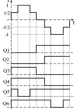
combinations required to generate a five-level current waveform are listed in Table 1. “0” means the switch is OFF, “1” means the switch is ON. Figure 5 shows the operation principle for five-level output current waveform generation, i.e. +I, +I/2, 0, -I/2 and -I current-five-levels.
Figure 4. Proposed five-level common-emitter CSI
Figure 5. Operation principle of five-level current waveform generation
Table 1. Switching states of proposed five-level CSI Q1 Q2 Q3 Q4 Q5 Q6 Output
0 0 1 1 0 1 +I
0 0 1 1 1 1 +I/2
1 0 0 1 1 1 0
1 1 0 0 1 1 -I/2
1 1 0 0 1 0 -I
Figure 6. Experimental test circuits of five-level common-emitter CSI
2.2. DC Current Source Circuits and Its Current Control
working as DC current supply. Figure 6 shows the circuit configurations of the five-level common-emitter CSI including the chopper circuits as DC current sources generator. The chopper circuits consist of four controlled switches, i.e. QC1, QC2, QC3 and QC4, controlling four DC currents flowing through the smoothing inductors L1, L2, L3 and L4. Four free-wheeling diodes (DF) are used to keep continuous currents flowing through the inductors.
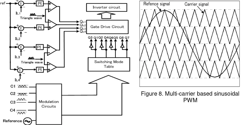
The current controller of the chopper circuits for DC current generation is presented in Figure 7. Proportional integral (PI) regulators are independently applied to control the currents flowing through the smoothing inductors, which determine the amplitude of the PWM output current waveform (IPWM) simultaneously. Making the inductor currents (IL1, IL2, IL3 and IL4) follow the reference current (Iref) is the objective of this current regulator. The gating signals of the chopper switches are generated by comparing the error signals of the detected steady state currents flowing through the smoothing inductors, and a triangular waveform after passing through the PI regulator. This signal is used to control the duty cycles of the chopper switches to obtain balanced and stable DC currents IL1, IL2, IL3, and IL4.
Figure 7. Current control diagram
Figure 8. Multi-carrier based sinusoidal PWM
2.3. PWM Modulation Strategy
In order to obtain a better output current waveform, a pulse width modulation (PWM) technique is applied, instead of a staircase waveform operation. Staircase waveform can easily be obtained at the fundamental switching frequency, so switching losses can be negligibly low. However more distortion of the output waveform is generated and a larger filter is needed. In this paper, a level-shifted multi-carrier based sinusoidal PWM technique is employed to generate the gate signals for the CSI power switches to obtain the PWM current waveforms as shown in Figure 7, and Figure 8 in more detail. All carrier waveforms (C1, C2, C3 and C4) are in phase with the identical frequency. The frequency of the reference sinusoidal waveform determines the fundamental frequency of the output current waveform, while the frequency of triangular carrier waves gives the switching frequency of the power switches. An M-level output current waveform using this modulation requires (M-1) triangular carriers with the same frequency [13]-[15].
3. Research Method
switching characteristics of the RB-IGBTs, power MOSFETs (FK30SM-6) in series with fast recovery diodes (HFA16PB120) were also used as power switches of the inverter. The experimental circuit specifications are listed in Table 2. The control circuits of choppers and inverter were built using mixed analog and digital circuits with opto-coupler as isolations between control circuits and power converter.
Table 2. Test parameters
Parameter Value Smoothing inductors of chopper 1 mH
Power source voltage DC 160 V Switching frequency 22 kHz Filter capacitor (Cf) 5 F
Load R= 6Ω, L= 1.2 mH Output current frequency 50 Hz
4. Results and Discussion
Figure 9 shows the experimental waveforms of the five-level CSI showing the load current, five-level PWM output current, and one of the DC current source waveforms obtained using 1 mH smoothing inductors. The total harmonic distortion (THD) of the five-level PWM current is 4.19% calculated up to 40th harmonic components. As can be seen in the figure, low distorted sinusoidal load current waveform was obtained after filtering by a small 5-µF filter
capacitor. Figure 10 shows the conduction loss characteristics of the five-level CSI using the RB-IGBTs, and power MOSFETs in series with fast-recovery diodes. As can be seen in the figure, the RB-IGBTs generate smaller loss for higher output power of five-level CSI.
Figure 9. Load current (ILoad), five-level current (IPWM) and smoothing inductor current waveforms (IL); (scales: amplitude 10 A/div, time 0.4 ms/div)
diodes. This figure shows that the RB-IGBT has slower reverse recovery current than the fast-recovery discrete diode connected in series with power MOSFET.
Figure 10. Conduction loss characteristics
Figure 11. Efficiency comparison for each kind of power switches
Figure 12. The enlarged figures of PWM output current: using reverse-blocking IGBTs (upper graph), and using power MOSFETs in series with discrete diodes (lower graph); (scales:
5. Conclusion
This paper presented experimental test results of the new five-level common-emitter CSI built using RB-IGBTs. The performance characteristics of the RB-IGBTs and power MOSFETs with series discrete diodes were also investigated. The results show that using RB-IGBTs, the efficiency of the power converter will increase. It is caused by the elimination of the losses caused by the discrete diodes connected in series with the power MOSFETs. However, it is also confirmed that the recently available RB-IGBTs have slow reverse recovery current than the discrete fast-recovery diodes connected in series with power MOSFETs.
References
[1] Rodiguez J, Jih-Seng L, Peng FZ. Multilevel inverter: a survey of topologies, controls, and application.
IEEE Transactions on Industrial Electronics. 2002; 49(4): 724-738.
[2] Malinowski M, Gopakumar K, Rodriguez J, Pérez MA. A survey on cascaded multilevel inverters.
IEEE Transactions on Industrial Electronics. 2010; 57(7): 2197-2206.
[3] Zhihong B, Zhongcao Z. Conformation of multilevel current source converter topologies using the
duality principle. IEEE Transactions on Power Electronics. 2008; 23(5): 2260-2267.
[4] Xu D, Zargari NR, Wu B, Wiseman J, Yuwen B, Rizzo S. A medium voltage AC drive with parallel
current source inverters for high power application. Proceedings of IEEE Power Electronics Specialist Conference (PESC). Recife. 2005; 2277-2283.
[5] Kwak S, Toliyat HA. Multilevel converter topology using two types of current-source inverters. IEEE
Transactions on Inductry Applications. 2006; 42(6): 1558-1564.
[6] Barbosa PG, H Braga HAC, Barbosa MC, Teixeria EC. Boost current multilevel inverter and its
application on single phase grid connected photovoltaic system. IEEE Transactions on Power
Electronics. 2006; 21(4): 1116-1124.
[7] Antunes FLM, Braga AC, Barbi I. Application of a generalized current multilevel cell to current source
inverters. IEEE Transactions on Power Electronics. 1999; 46(1): 31-38.
[8] McGrath BP, Holmes DG. Natural current balancing of multicell current source inverter. IEEE
Transactions on Power Electronics. 2008; 23(3): 1239-1246.
[9] Zargari NR, Rizzo SC, Xiao Y, Iwamoto H, Satoh K, Donlon JF. A new current source converter using
a symmetric gate-commutated thyristor (SGCT). IEEE Transactions on Industry Applications. 2001;
37(3): 896-903.
[10] Klumpner C, Blaajerg F. Using reverse blocking IGBTs in power converters for adjustable- speed
drives. IEEE Transactions on Inductry Applications. 2006; 42(3): 807-816.
[11] Suroso, Noguchi T. Three-level current-source PWM inverter with no isolated switching devices for
photovoltaic conditioner. IEEJ Transactions on Industry Application. 2009; 129(15): 505-510.
[12] Suroso, Noguchi T. A New Three-level current-source PWM inverter and its application for grid
connected power conditioner. ELSEVIER International Journal of Energy Conversion and
Management. 2010;51(7), 1491-1499.
[13] Kumar MR, Lenine D, Babu CS. A variable switching frequency with boost power factor correction
converter. TELKOMNIKA. 2011; 9(1): 47-54.
[14] Wu B. High Power Converters and AC Drives. New Jersey: A John Wiley & Sons. 2006: 189-219.
[15] Tobert LM, Peng FZ, Habetler TG. Multilevel PWM methods at low modulation indices. IEEE