DEVELOPMENT OF COMMUNICATION PROTOCOLBASED ON LOW VOLTAGE
DISTRIBUTION AUTOMATION SYSTEM
M.M.AHMED
w.
L.
soo
Paper Presented at the International Conference on Engineering and ICT (ICEI 2007), 27 -28 Nov 2007, Hotel Equatorial Melaka.
Development of Communication Protocol
Based on Low Voltage Distribution
Automation System
M. M. Ahmed, Member, IEEE and W. L. Soo
Abstract--This paper presents the development of a customer ide distribution automation system (DAS) for operating and ontrolling low voltage (LV) down stream of 415/240V by using IJe Tenaga Nasional Berhad (TNB) distribution system. ;0pervisory Control and Data Acquisition (SCADA) based temote Terminal Unit (RTU) along power line communication
PLC) system are used for DAS development that practically imulates the down stream distribution system functions in an utomated manner. It is the first DAS research work done on ustomer side substation for operating and controlling between Ile consumer side system and the substation. Most of the work , focused on building Human Machine Interface that provides a ;raphical operator interface function to monitor the system. The Inman Machine Interface of SCADA system is developed using ustomized software and an RTU microprocessor and its oftware implements.
ndex Terms-- SCADA system, RTU, RS-232, RS-485,
;erial Modules, Modbus, TCP/IP, Master-Slave.
I. INTRODUCTION
A SCADA system consists of a number of remote erminal units (RTUs) collecting field data and sending that lata back to a master station via a communications system. the RTU provides an interface to the field analog and digital ;ensors situated at each remote site. The master station lisplays the acquired data and also allows the operator to ierform remote control tasks. The RTU provides an interface o the field analog and digital sensors situated at each remote ;ite.
The advent of microprocessor has changed the :Unction of RTUs. In the early days, RTU did not have the :apability to program to specific applications and they iepended on a central controller to send or request data from ievice. Today, modern RTUs are capable to read and act 1pon values of discrete and analog sensor devices through a :ommunication link such as wire, fiber optic and etc.
GE-Harris in Calgary Canada is one of suppliers of modern RTUs used in substation automation. GE-Harris has a
This research was supported by Kolej Universiti Teknikal Kebangsaan \1alaysia (KUTKM).
W.L Soo is with the Department of Electrical Engineering, UTeM, Malaysia. M.M Ahmed is with the Department of Electrical Engineering, UTeM, Malaysia (e-mail: [email protected]).
large protocol library which allows the RTU to talk to most IED (Intelligent Electronic Devices).
The RTU is usually designed to monitor parameters such as bus-line volts, current, active power, reactive power, status of circuit breakers, switches and isolators, fault detection, temperature level, pressure, flow etc. It can be mounted on the equipment, line etc. It can be a line pole/tower mounted type, where a water-proof enclosure protects internal circuits such as the switch control circuit and communication circuit from outside moisture.
Recent RTU design focus has been on the ability of the unit to support multiple open communication protocols, such as modbus, modbus TCP, Ethernet IP, Profibus and Device Net. User friendly local human machine interfaces are also featured in many RTU designs that can operate independent from the central SCADA computer.
II. COMMUNICATION ARCHITECTURE
There are three main physical communication architectures that can be combined in one communication system which are point-to-point architecture, multi-point architecture and relay station architecture (1].
Point-to-point architecture involves data exchange between two stations only. One station can be setup as the master and the other one as the slave. It is possible for both stations to communicate in full-duplex mode or half-duplex mode with only one frequency. Full-duplex mode means transmitting and receiving two separate frequencies.
Multi-point architectures involve configuration of one master and multiple slaves. Data is passed between the master and each one of the slaves. If two slaves need to transfer data between each other, they would do so through the master. This research is based on this architecture where one RTU can be connected to many modules acted as slaves.
International Conference on Engineering and JCT (ICE! 2007)
Ill. COMMUNICATION ARCHITECTURE
There are two commonly used options which are a polled approach or a contention approach [2].
This research will be based on polled approach. Polled approach is where the master is in total control of the communication system and makes regular requests for data to be transferred to and from each one of a number of slaves. The slave only responds on a request from the master and do not initiate the transactions. If a slave does not respond in a defined time, the master then retries and then marks the slave as unserviceable before trying the next slave node in the sequence. It is possible to retry the unserviceable slave again on the next cycle of polling.
Contention method does not involve controlling master and contending of individual stations for access to the transmission medium. In a situation where RTU embarks to communicate with another RTU, a technique used is to respond to a poll by the master station with a message with a destination address other than that of the master station. The master station will then examine the destination address field of the message received from the RTU and if it does not observe its own, retransmits it onto the appropriate remote station.
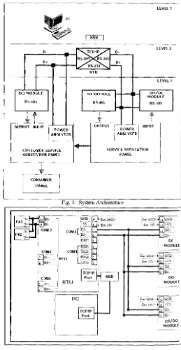
IV. SYSTEM ARCHITECTURE
The system architecture for this research is divided into three levels as shown in Fig. 1. Level 1 consists of SCADA equipment or Human Machine Interface (HMI). Personal computer is equipped with graphical user interface (GUI) that runs under the Microsoft Windows XP platform using InduSoft software. The GUI provides monitoring for service substation and customer service substation, real-time data, data trending, data archiving, display and recoding alarm messages, show communication status of the system and control execution. Systems operations personnel use this equipment to control and monitor the input and output remotely.
Level 2 consists of embedded Ethernet RTU. RTU communicate using a master-slave technique. In this technique, the master device will initiate transactions while the slave devices will respond by supplying the requested data to the master, or by taking the action requested in the query. The control program is downloaded into the RTU. The logic programming is configured by using RTU software
manufactured by vendor. RTU is responsible for
communicating with the supervisory system using TCP/IP protocol. RTU also acts as converter to link the SCADA equipment to the digital input (DI) module, digital output (DO) module and DI/DO module using RS485 protocol. The RTU also receives data from power analyzer by using RS-485 port using modbus protocol. RTU can handle control functions without the PC in real time.
Level 3 consists of I/O modules and three panels. Three types of I/O modules are used which are the DI module, DO module and combination of DI/DO module. DI/DO module receives signal from ELCB in the customer service substation panel. It then converts the signal into RS485 standard signal and transfers to RS485 network. This signal is received by RTU. DI/DO module receives signal
from the RTU to trigger certain actions to the relays as output devices. DI module and DO module are responsible to receive and send signals to input and output of service panel. Power analyzer is a power measurement metering device that displays volts, amps, watt, vars and etc. It sends data directly to the controllers to be displayed at the monitor.
In actual practice, service substation panel is connected to more than one customer service substation panel. In this research, service substation panel is only connected to one customer service substation panel. Customer service substation panel is connected to the consumer panel. In this case, the consumer panel consists of lights as the control loads. Fig. 2 describes the wiring diagram based on the system architecture.
D-O•
DO MODULE
RS-4115
'
..
..
OUTPUT INPUT
POWER t ANALYSER
CUSTOMER SERVICE SUBSTATION PANEL
;
CONSUMER
PANEL
LEVEL 1
LEVEL 2
セ@
o.O• 5 2 ,_
RTU
LEVEL 3
DI MODULE MODULE DO/DI
RS-4115 RS485
r
'
•
OUTPUT I POWER セ@
i
INPUT ANALYSERi.----
SERVICE SUBSTATIONPANEL
Fig. I. System Architecture
RTU
.2E:,:
H - - - - < 1 : ュセ@
DO MODULE
Em gnZ^Mエセ@ セセBdL@ fat :!..f'.--+5]-\ 5
_2 _セZ@ . _ _ _ _ _.,_ D>
DI/DO MODULE
[image:3.605.271.530.210.710.2]V. RTU SPECIFICATION
Embedded Ethernet RTU is used in this research ject. The RTU is designed as embedded RTU. Therefore, , software can be downloaded into it. Users can easily :iloy c language to develop their own programs. This RTU ports a battery backup SRAM board and Flash-Rom rd, providing non-volatile mass storage from 128K bytes )4K bytes. This RTU is powered by an 80188-40 processor h 5 l 2K bytes of static RAM and 5 l 2K bytes of Flash mory.
This RTU needs supply from de power that can be where from
+
30V to+
1 OV. This controller provides one 1al RS-232 port and one RS-485 port and can be mounted one I/O expansion board to implement various I/O ctions such as D/I, D/O, AID, DIA, Timer/Counter, Flash mory and battery ba£kup SRAM.This RTU is equipped with dual watchdog features ich are the software watchdog and hardware watchdog. If
module is down, it can be rebooted automatically. If the nmunication network is disconnected or under some
mal-ctions, the host PC and the individual modules can not nmunicate with each other, which can also activate the tware watchdog.
The EEPROM is designed to store the data which is changed very frequently. These data are module ID, com
t configuration settings and small databases. The erase
1 write cycle of the EEPROM is limited.
The 2-wire RS-485 port is designed to directly drive , series modules. The RTU is equipped with a Self Tuner .IC for all RS-485 ports. The Self-Tuner ASIC will auto ects and controls the send and receive directions of the 485 network. The general feature of the RTU is illustrated Fig. 3.
Flash-R.OM=512K
.
---!
16 bits timer
_,.. EE.
ーNー⦅ッセ@
I ·
NpセMMM
I
CO:\Ic.RS-+&5 I ___....+5V••
U ;er defin'i!<I
I
pm=l4I
Fig. 3. General Controller Block Diagram
The IEEE 802.3 standard documents (ISO 8802.3) pport various cable media and transmission rate up to !Mb/s such as 10Base2, lOBase 5, lOBaseT, IOBase F,
セ。ウ・U@ and 10Broad36[3].
This RTU provides one on-board 1 OBaseT port that equipped with a RJ-45 connector. The lOBaseT interface
supports a maximum of 100 meters of cable length between the RTU and the network hub.
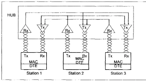
Based on IEEE 802.3 standard documents, IOBaseT standard for Ethernet networks uses A WG24 unshielded twisted pair (UTP) cable for connection to a node with a range of 0.4 to 0.6 mm conductor diameter. The physical topology of the standard is a star, with nodes connected to a wiring hub, or concentrator. Concentrators can then be connected to a backbone cable that may be coax or fiber optic. The node cable has a maximum length of 100 meters consists of two pairs for receive and transmit and is connected via RJ45 plugs. Fig. 4 shows schematically how the lOBaseT nodes are interconnected by the hub.
HUB
Tx Rx Tx maセ@ Tx Rx
MAC MAC
DTE DTE
Station 1 Station 2 Station 3
Fig. 4. Schematic Diagram of I OBaseT system
This RTU supports TCP/IP protocol suite that uses a 4-layer models which are the physical layer, network layer, transport layer and application layer described in Fig. 5.
4 Application Layer TELNET, FTP, SMTP, DNS
3 Transport Layer TCP, UDP
2 Network Layer IP, ICMP, ARP, RARP
1 Physical Layer Packet radio, Ethernet
Fig. 5. TCP/IP 4 Layer Models
IP is referring as internet protocol. IP (RFC 791) is responsible for the delivery of packets or datagrams between hosts. It forwards and delivers datagrams on the basis of IP address attached to the datagrams. The IP address is a 32-bit entity containing both the network address and the host address. Since this number is difficult for human beings to remember, it is converted into format such as 192.100.100.1. The default IP for this RTU is 192.168.255.1.
[image:4.603.252.506.216.358.2] [image:4.603.259.496.433.570.2] [image:4.603.13.239.460.640.2]International Conference on Engineering and JCT (ICE! 2007)
shows the general structure according to class internet address.
I 7 bib 24 bih
I
o
I
:.;c11nI
r.---
14 bit' • I • l6bil\ --+jJ 1 J 0
I
>:ctlD- - - 21 bir; - - - . . i 8 bib I
" ' I
•1---
28 bibJ I
I
1I
1I
0 \1ultica'1 addrc"Fig. 6. Internet Address
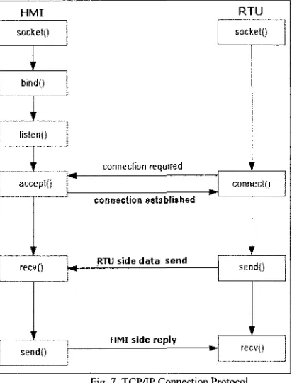
The communication between HMI and RTU is using fCP/IP protocol. A socket is a combination of port number md IP address. HMI will always listen for any request from :he RTU. RTU will request a connection to the HMI and HMI .vill accept the connection before data can be send or ·eceived.
HMI RTU
I
socket()I
connection required
'
I
accepl(i iI
connect()I
connection established
"
RTU side data send I"
send()
I
I
I_ recvO ',..., . ; 1 - - - - ' - - - l
}セᄋ@
""";,. '""" ..
セi@MMMNMセi@
j send()
i
.
recv{)Fig. 7. TCP/IP Connection Protocol
The RTU software provided by the vendor can be 1sed to upload logic programming into the RTU. To establish 'Ethernet" communication, internet address and port number ire set as shown in Fig. 8.
The internet community can access Modbus at a reserved system port 502 on the TCP/IP stack.
VI. I/0 MODULES
The series modules, including D/I, D/O, AID, DI A, Timer/Counter and MMI modules, will be directly connected to RS-485. These series modules can connect a maximum of 256 modules to the RS-485 network. The module address can be changed from 00 to FF, a total of 256 maximum. The series modules can be programmed to 1200, 2400, 4800, 9600, 19200, 38400, 57600, 115200, a total of 8 different speeds.
The I/O modules used in this research are DI/DO module which is an 8 channel digital output and 4 channel digital input module, DI module which is a 16 channel digital input and DO module which is a 13 channel digital output
These modules can be remote controlled by a set of commands. The PC will send out a command string to the RTU either by TCP/IP protocol or RS232 protocol. RTU converts this command into a 485 before it sends to RS-485 network.
A. Serial communication
The Electronics Industry Association (EIA) had introduced the interface for asynchronous serial standard which is RS-232-C in1962. The standard specifies signal voltage levels and handshaking signals to be used when serial data is being sent between data terminal equipment (DTE) such as computer, and data communication equipment (DCE) such as modem. With the definition by the EIA committee, this standard has become widely accepted because it improves compatibility between equipment and an RS-232 serial port. However RS232 standard restricts the data rate to less than 2000 bytes per second and cable lengths to less than 50 meter. Despite this disadvantage, the RS-232 standard is still commonly used.
[image:5.597.262.500.38.147.2] [image:5.597.5.211.309.579.2]tiefore stan data panty ;top idle
Fig. 9. A Serial Data Byte
The transmission starts at the left hand side. Each bit ·ill be true or false for a fixed period of time, determined by 1e transmission speed. The voltage/current on the line is 1ade true or false. The width of the bits determines the ossible bits per second (bps). The value shown before is used
> transmit a single byte. Between bytes, and when the line is
Ile, the txd is kept true, this helps the receiver to detect ·hether a sender is present or not. A single start is sent by 1aking the Txd false.
In Fig. 9, before signal is a period where no bit is eing sent and the line is true. Start is a single bit to help the rstem synchronized. Data contains 8 bits. The value shown ere is a byte with the binary value of 0010010 where the
セ。ウエ@ significant bit is sent first.
Following the data is a parity used to check if the
yte was sent properly. In this case, there is one bits set in the ata byte. If using even parity, the bit would be true if the >tal number of ls in the data is even. If using odd parity, the it would be false if the total is odd, it thus provides a check ;; to whether a bit has been corrupted in the transfer.
The stops bits allow a pause at the end of the data. lne or two stop bits can be used. Idle is a period of time •here the line is true before the next byte.
The transmission speed is the maximum number of its that can be sent per second. The unit for this is baud. The aud rate includes the start, parity and stop bits. For example 9600 baud transmission of the data in the figure above rould transfer up to 9600/ (1+8+1+2) = 800 bytes for every econd. Lower baud rates are 120,300, l.2K, 2.4K and 9.6K. ligher baud rates are 19.2K, 28.8K, and 33.3K.
B. RS-232 Standard
The RS-232c standard 1s based on a low/false oltage between + 3 to + l 5V, and a high/true between 3 to -5V.
Fig. 10 shows some of the common connection chemes. In all methods, the transmit data (txd) and receive ata (rxd) lines are crossed so that the sending txd outputs are 1to the listening rxd inputs when communicating between omputers.
com .,._ _ _ _ _ _, com
セᄋッューオエ・イ@ Computer txd A rxcl txd rxd
」セ@ 」セ@
rts ns
Fig. 10. RS-232 Connection
Computer
B
Common connectors for serial communications are shown in Fig. 11. These connectors are either male (with pins) or female (with holes), and often use the assigned pins shown. The DB-9 connector is connector with a nine pin.
C. RS-485
DB-9
(1
2 3}s}
\ opp8u90
i\.___(_>
o o
o__J
1-DCD
2 - RXD (receive data) 3 - TXD (transmit data) 4 - DTR (data tenninal ready)
5 -COM (common) 6 - DSR (data ;,et ready) 7 -RTS (request to send)
8 -CTS (clear to send)
9 - RI Positive Voltage
Fig. 11. RS-232 DB9 Connector
RS-485 is a two wire industrial field bus. Compared to the traditional RS-232, it uses differential transmission mechanism to transfer electrical levels, and has a significant improvement in the performance of anti-interference. Without repeater, the transmission distance can reach up to 1.2 KM at the speed of 9200bps. Only one pair of twisted wire is needed to send and receive data at a long distance in a high speed.
RS-485 permits network connection on two wires and provides for reliable serial data communication for distances of up to 1200m and data rates of up to lOMbps. Up to 32 line drivers permitted on the same line and up to 32 line receivers are permitted on the same line [5). The line voltages range between -l.5V to -6V for logic 'l' and + 1.5V to +6V for logic 'O'. The major enhancement ofRS-485 is that a line driver can operate in three states called as tri-state operation. The three states are logic 'O', logic '1' and 'high-impedance', where it draws virtually no current and appears no presence at all on the line.
VII. TRANSACTION USING MODBUS PROTOCOL
TABLE I
COMMUNICATION DEVICE SETTING
Device Set Com Baud IP
ID Port rate Address
DO MODULE OxOl 2 9600
-DI MODULE Ox02 2 9600
-DO/DI MODULE Ox03 2 9600
-Power Analyzer, OxOl 3 9600
-PAI
Power Analyzer, Ox02 3 9600
-PA2
RTU OxOl TCP/I - 192.168.2
p 55. l
PC - TCP/I -
[image:6.602.2.247.39.114.2] [image:6.602.293.451.94.275.2]International Conference on Engineering and JCT (ICE! 2007)
Modbus is the protocol commonly used for SCADA applications. The Modbus transm1ss10n protocol was developed by Gould Modi con for process control systems [ 6). A recent survey in the well-known American Control Engineering magazine indicated that over 40% of industrial communication applications use the Modbus protocol for interfacing. [7]
In this research, RTU communicate using a master-slave technique. The modbus protocol provides for one master and up to 246 slaves. Only the master initiates a transaction. All slaves need to have their own address or set ID. This is shown in TABLE 1.
The master which is the RTU can initiate a broadcast message to all slaves. Slaves return a message called a 'response' to queries that are addressed to them individually. The Modbus protocol provides frames for the transmission of messages between master and slaves. The information in the message is the address of the intended receiver, what the receiver must do, the data needed to perform the action and a means of checking errors.
The slave reads the messages, and ifthere is no error it performs the task and sends a response back to the master. The information in the response message is the slave address, the performed action, the result of the action and a means of checking errors. Data can be exchanged in two transmission modes:
• ASCII - readable, used e.g. for testing
• RTU - compact and faster; used for normal operation(hex)
The Modbus also provides an error check for transmission and communication errors. Communication errors are detected by character framing, a parity check, a redundancy check or Cyclic Redundancy Check (CRC). All functions supported by the Modbus protocol are identified by an index number. They are designed as control commands for field instrumentation and actuators and are as follows:
•
•
•
•
•
•
•
Coil control commands for reading and setting a single coil or a group of coils
Input control commands for reading input status of a group of inputs
Register control commands for reading and setting one or more holding registers
Diagnostics test and report functions Program functions
Polling control functions Reset
Modbus protocol can be broken down into five sections which are message format, synchronization, memory location, function codes and exception responses.
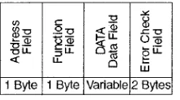
A transaction consists of a single request from the host to a specific secondary device and a single response from that device back to the host. Both of these messages are formatted as modbus message frames [8]. Each such message
frame consists of a series of bytes grouped into four fields as described in Fig. 12.
"
.::.<.<J) c al
gs :!2 .2u <:{ ]! ..cu セHjj@ Rセ@ t-: LL ()-a;
u
-セセ@
gu:
uLL :;LL
ct: u.. 0
w 1 Byte 1 Byte Variable 2 Bytes
Fig. 12. Format ofModbus message frame
The first field in each message frame is the address field, which consists of a single byte of information. This byte identifies the controller to which the request is being directed. The resulting response frame begins with the address of the responding device. The second field is the function field which also consists of a single byte of information. This byte identifies the function that the target controller is to perform.
Each request frame contains a function code that defines the action expected for the target controller. The meaning of the request data fields is dependent on the function code specified.
The third field is the data field, which varies in length according to which function is specified in the function field. This field contains information that the controller may need to complete the requested function. The last two bytes comprise the error-check fields. The numeric value of this field is calculated by performing a cyclic redundancy check (CRC-16) on the message frame. This error checking assures that the devices do not react to messages that may have been changed during transmission. Fig. 13 shows an example of message frame used in this research to read two words value of variable Vl by using modbus function 3.
Modbus address 0000 is associate with network address i
Req ls1v @3
I
Read2wordsI
Ans: Slv 03
High word
Fig. 13. Read long word by Modbus
Fig. 14 shows an example of message frame used in this research to write two words value of variable VI by using modbus function 16.
Req: slv rn 00 00
Ans lslv
I
1 OI
00I
00loo I
02 lcrcH セイ・ャ@I
[image:7.595.324.450.76.146.2] [image:7.595.271.510.458.554.2]VIII. MODBUS/BUS 7000 FUNCTION BLOCKS
MBUS_R
en Q
1 SLAVE_
セfXS@ ADDR
3 CODE 4 NUM_
N1 N2 N3 N4 NS_ N6_ N7_ NB_ N9 N10_ N11 comm
> - - l
ur_1 ur_2 ur_3 ur_4 MBUS_R en 1 SLAVE
-16#FC ADDR
3 CODE
-4 NUM
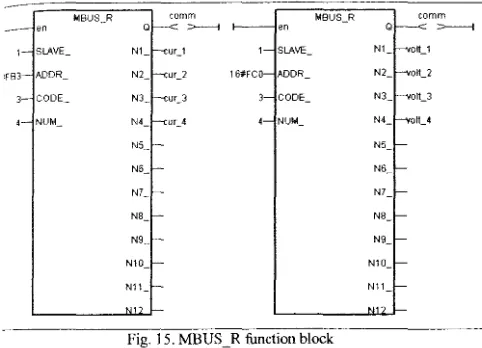
-Fig. 15. MBUS_R function block
comm Q >---! N1 ott_1
N2_ olt_2
N3_ 011_3
N4_ olt_4
NS N6_ N7 N8_ N9_ N10_ N11
Power analyzer communicates with RTU using com by RS-485 protocol. In order to read data from power 1lyzer, the RTU software provides two 'MBUS_R' function 1cks described in Fig. 15 are used. One function block is to rieve phase-current data and another function block is to rieve phase-voltage data. Slave is the 'address' of power 1lyzer which is set to 'I '. The data for current values are rting from 'I 6#FB3 '. '16#' indicates hexadecimal address. e data for voltage values start from 'l 6#FCO'. The nmand of read and write will be used in function code 3. ur words of the data wiU be retrieved during read nmand.
The serial modules can be assigned to input and tput variables by using function blocks. Function block for )/DI module is described in Fig. 16 which is already ailable in RTU software libraries. Address is set according 'Set ID" that is already configured in the modules. If the mmunication between the RTU and serial modules are
セ」・ウウヲオャL@ the 'Q' pin will generate a true state. 'Q' pin will in false state if communication is failed between the RTU d the modules.
DI/DO
en Module
comm_out_1_c
Q_ >---I
ADR - 811 nput_c
lamp1_c 801 812_
lamp2_c 802 - 813_
lamp3_c 803 814
lamp4_c 804
done5_c 805 -lamp6_c 806
lamp7 _c 807
reset_elcb_c
Fig. 16. Function Block of DO/DI Module
IX. COMMAND FORMAT OF DI/DO MODULE
Command format can be used to send and received data from HMI to DI/DO modules. The command format consists of leading, address, command and checksum. The response format consists of leading, address, data and checksum. For example to change module address from 01 to 02 a command "%0102400600" is written in the HMI. RTU will send "!02" to HMI ifthe new configuration is successful. Table 2 elaborates the command and received syntaxes.
TABLE2
SET MODULE CONFIGURATION
Command Syntax Description
%AANNTTCCFF[CHK](cr) %- a delimiter character
AA - address of setting module (00 to FF) NN - new address for setting module (00 to FF) TT - type 40 for DIO module
CC - new baudrate for setting module
FF- new data format for setting module
Response Svntax Description
!AArCHK](cr) Valid Command
?AA[CHK](cr) Invalid Command
X. READ/WRITE TO THE HMI FROM THE RTU
Data from RTU system is made available to other software program or Human Machine Interface (HMI) devices by declaring the variable with a "Network Address". The valid network addresses for RTU systems are from 1 to FFF in hexadecimal format. Other software programs or HMI devices will access the RTU information through these network addresses. Tags declared in HMI software are assigned to the respective network address assigned in the RTU system.
XI. CONCLUSIONS
[image:8.600.0.241.65.239.2] [image:8.600.10.235.512.699.2]International Conference on Engineering and JCT (ICE! 2007)
[!]
[2]
[3]
[4]
[5]
[6]
[7]
[8]
[9]
[JO]
[II]
XII. REFERENCES
Gordon Clarke, Practical Modern SCADA protocols: DNP3, 60870.5 and Related Systems, 2004, ISBN 07506 7995, pp.28
Gordon Clarke, Practical Modern SCADA protocols: DNP3, 60870.5 and Related Systems, 2004, ISBN 07506 7995, pp.31
Gordon Clarke, Practical Modern SCADA protocols: DNP3, 60870.5 and Related Systems, 2004, ISBN 07506 7995, pp.316
Hugh Jack, "Automating Manufacturing Systems with PLCs'', Version 4.7, April 14,2005, pp.643
John Uffenbeck,Microcomputers and Microprocessors, 2000, 1991, 1985 by Prentice Hall, ISBN 0-13-209198-4,pp 509
Gordon Clarke, Practical Modern SCADA protocols: DNP3, 60870.5 and Related Systems, 2004, ISBN 07506 7995, pp.45
Gordon Clarke, Practical Modern SCADA protocols: DNP3, 60870.5 and Related Systems, 2004, ISBN 07506 7995, pp.56
Gordon Clarke, Practical Modern SCADA protocols: DNP3, 60870.5 and Related Systems, 2004, ISBN 07506 7995, pp.47
ICP DAS, 7188E/843X/844X/883X/884X TCP/IP Library User's Manual, Ver. 1.0 Copyright 2002 [Online] Available: www .icpdas.com Customized Non-interruptible Distribution Automation System, Short Term Project No. PJP/2006/FKE (1), UTeM, 2005-2006
Intelligent Distribution Automation System: Customized SCADA Based Rtu For Distribution Automation System, M.Sc. Research Project, UTeM, 2005-2007.
XIII. BIOGRAPHIES
Dr. Musse Mohamud Ahmed is a senior lecturer at Faculty of electrical Engineering, UTeM. He graduated from Somali National University (SNU) in 1984, NWFP University of Engineering &
Technology, Peshawar, Pakistan in 1996 and Universiti Teknologi Malaysia (UTM) in 2000 and got his B.Sc., M.Sc. and Ph.D. respectively. He worked Multimedia University (MMU), as lecturer at the Faculty of Engineering & Technology in Malacca campus from 2000 to 2002. He joined UTeM in March 2002 as a lecturer. In October 2002, he was appointed as deputy dean, postgraduate studies, research &
development at the Faculty of Electrical Engineering, UTeM, a position he held till March 2007. Since then he has been working in UTeM.
Dr. Musse has been IEEE-PES member for seven years and Executive Committee for the last five years. His research interests include: Distribution Automation System, Power System Operation and Control Simulation &
Modeling of Large Power Systems, Intelligent Power Systems, Energy &
Renewable Energy and Risk Assessment of Electricity Supply