i
THE DEVELOPMENT OF VISUAL INDICATOR
FOR ENGINE MAINTENANCE IN CARS
MOHD ARIZAM BIN ABU SEMAN
This report
is submitted in partial fulfillment for Bachelor of Mechanical Engineering (Automotive)
Faculty of Mechanical Engineering Universiti Teknikal Malaysia Melaka
“I certify that this report is my own work except summary and references whereby the sources has been clearly justified”
Signature :……….
iii
ACKNOWLEDGEMENTS
Alhamdulillah, thank God because I have completed my final year project. First of all, I would like to take this opportunity to express my sincere appreciation to Dr Janatul Islah Bt. Mohammad, my supervisor for her guidance and encouragement in order to succeed this project and to the laboratory management especially the technicians for their co-operation.
ABSTRACT
v
ABSTRAK
TABLE OF CONTENTS
PAGES
ADMISSION ii
ACKNOWLEGDEMENTS iii
ABSTRACT iv
TABLE OF CONTENTS vi
LIST OF FIGURES vii
CHAPTER 1 INTRODUCTION 1.1Introduction 1 1.2Objectives 2 1.3Scope of Work 2 1.4Problems Statement 2 1.5Schedule of Activities 4 1.6Report Structure 5
CHAPTER 2 LITERATURE REVIEW 2.1 Introduction 6 2.2 Internal Combustion Engine 7 2.3 Mechanical Friction in Engine 7
2.4 Lubrication System of Engine 8
vii
PAGES
CHAPTER 3 RESEARCH METHODOLOGY
3.1 Introduction 15
3.2.1 Bernoulli’s Principle 15
3.2.2 Pressure Transducer 18
3.2.3 Valve Actuator 19
3.2.4 PID Controller 20
3.3 Design of engine Oil Control System 21 3.3.1 Physical and Design Parameters 22 3.4 Development of Engine Oil Level Control System 23
3.4.1 Reserve Oil Pan 23
3.4.2 Main Oil Pan 24
3.4.4 Valve Actuator 26
3.4.5 MATLAB Simulink Application 28
CHAPTER 4 RESULT 29
4.1 Introduction 29
4.2 Analysis without Leakage Condition 31
4.3 Analysis with Leakage Condition 37
CHAPTER 5 DISCUSSION 44
5. 1 Introduction 44
5.2 Analysis without Leakage Condition 44 5.3 Analysis with Leakage Condition 45
CHAPTER 6 CONCLUSION 46
FURTHERWORK 47
LIST OF FIGURES
FIGURE TITLE PAGES
1 Lubrication System of Engine [3] 3
2 Engine Oil Pan [3] 4
3 Gantt chart PSM 1 5
4 Gantt chart PSM 2 6
5 Engine Structure [3] 7
6 Lubricated surface showing reduction of friction [4] 8
7 Friction in Engine [3] 8
8 Engine Lubrication System [3] 10
9 Oil Level Is Checked Using Dipstick [5] 10
10 Engine Oil Pan [3] 16
11 Fluid Tank [13] 17
12 Pipeline [13] 18
13 Pressure Transducer [14] 20
14 Process Valve [15] 20
15 PID Blocks [7] 21
16 Time Function Form of PID Blocks [7] 21
17 Laplace Function Forms of the PID Blocks [7] 21
18 Engine Oil Level Control System 22
19 Reserve Oil Pan 24
20 Main Oil Pan 25
21 Transducer Block Diagram [10] 26
22 Transducer for Main Oil Pan 26
ix
FIGURE TITLE PAGES
24 Valve Actuator Block Diagram [8] 28
25 Valve Actuator 29
26 Engine Oil Level Control System 29
27 Graph of h2 Level (m) versus Time (s) 32
28 Graph of h1 Level (m) versus Time (s) 32 29 Graph of h2 Level (m) versus Time (s) 33
30 Graph of h1 Level (m) versus Time (s) 34
31 Graph of h2 Level (m) versus Time (s) 34
32 Graph of h1 Level (m) versus Time (s) 35
33 Graph of h2 Level (m) versus Time (s) 37
34 Graph of h1 Level (m) versus Time (s) 37
35 Graph of h2 Level (m) versus Time (s) 39
CHAPTER 1
INTRODUCTION
1.1 Introduction
2
1.2Objectives
The purpose of this project is to design and develop a visual indicator system for engine maintenance in cars. It is focusing on detection of the desired level of engine lubrication oil in the oil pan and then maintaining the level for any decreasing in case of leakage. Besides, the system consists of reserve oil pan, valve actuator, controller and sensor to perform the level maintaining process in the main oil pan.
1.3Scope of Work
The scope of this project consists of design and development for the visual indicator system using MATLAB/Simulink application and then performing the simulation. The desired volume of engine lubrication oil which should be maintained in main oil pan is 3.9L which is definitely compatible with 2.0cc engine.
1.4Problems Statement
Figure 1: Lubrication System of Engine [3]
Therefore, the relevant of this project is to design, develop and then simulate a visual indicator system as a solution idea in purpose of upgrading the maintenance system in cars. This idea actually is focusing on detection of the desired level of engine lubrication oil in the oil pan and then maintaining the level for any decreasing in case of leakage. This is in purpose of facilitation for automobile ownership responsibility related on engine maintenances.
4
1.5 Schedule of Activities
July 2007 – November 2007
Figure 3: Gantt chart PSM 1
Activity W
1 W 2 W 3 W 4 W 5 W 6 W 7 W 8 W 9 W 10 W 11 W 12 W 13 W 14 W 15 W 16
Study scope and objective on detail √ Problems Statement √
Literature Review √ √ √ √ √ √ √
Research Methodology
√ √ √
Simulation √ √
Submit Report (1st draft)
√
Submit Report (Final draft)
√
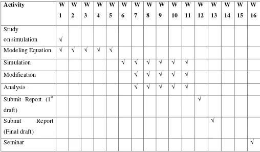
December 2007 – April 2008
Figure 4: Gantt chart PSM 2
Activity W
1 W 2 W 3 W 4 W 5 W 6 W 7 W 8 W 9 W 10 W 11 W 12 W 13 W 14 W 15 W 16 Study
on simulation √
Modeling Equation √ √ √ √ √
Simulation √ √ √ √ √ √
Modification √ √ √ √ √
Analysis √ √ √ √ √
Submit Report (1st draft)
√
Submit Report (Final draft)
√
6
1.6 Report Structure
Generally, Chapter 1 elaborates the objectives and scope of the project in detail. It is also includes a bit discussion on problems statement of the research which is to be solved in this entire project. Besides, it is also attach the schedule of activities for this entire project.
Besides, Chapter 2 discusses the problems statement which has been briefly stated in Chapter 1. The discussion is based on the previous studies of the research in theoretical.
Moreover, Chapter 3 discusses the methods of the research which is going to be used to develop the visual indicator. This chapter provides detail explanation on how the oil level control system will be developed. It also includes explanation on the components and materials which been used in the project.
Furthermore, Chapter 4 provides the result on the simulation of oil level control system by using MATLAB/Simulink application. The graphs of simulation result are also being attached for further discussion.
Besides, Chapter 5 provides the discussion on all of the results which obtained in simulation. This chapter also provides detail elaboration about the graphs.
Therefore, Chapter 6 concludes the report and suggests some work to be carried out for project furtherwork in future.
CHAPTER 2
LITERATURE REVIEW
2.1 Introduction
Commonly, the purpose of this literature review is to summarize the available previous study on theoretically that is related to engine maintenances system in car. The review includes basic information on maintenance systems of engine lubrication including engine parts and internal combustion engine operation.
2.2 Internal Combustion Engine
8
Figure 5: Engine Structure [3]
2.3 Mechanical Friction in Engine
Basically, the two solid surfaces will touch each other at the roughness high spots when they are in contact in an engine. The smoother the surfaces are machined, the lower will be the surface high points and the less will be the average distance separating them [2]. If one surface is move relatively to the other, the high points will come into contact so that resisting the friction. In addition, points of contact will become hot and sometimes trying to weld together [4]. Therefore, lubrication oil is added to the space between the surfaces in order to greatly reduce resistance of surface-to-surface motion. Lubricating oil adheres to the solid surfaces so that when one surface moves relative to the other, oil is dragged along with the surface. The oil holds the surfaces apart and one surface hydraulically floats on the other surface. Furthermore, the only resistance to relative motion is the shearing of fluid layers between the surfaces which is orders or magnitude less than that of dry surface motion.
Figure 6: Lubricated surface showing reduction of friction [4] Valve
Crankshaft Piston Combustion
Chamber Plug
Piston rings
Figure 7: Friction in Engine [3]
2.4 Lubrication System of Engine
Basically, the engine lubrication system is designed to deliver clean oil at the correct temperature and pressure to every part of the engine. The oil is sucked out of the pan into the pump, which is the heart of the system and then forced through an oil filter and pressure is being feed to the main bearings and to the oil pressure gauge. From the main bearings, the oil passes through feed-holes into drilled passages in the crankshaft and on to the big-end bearings of the connecting rod. Moreover, the cylinder walls and piston-pin bearings are lubricated by oil fling dispersed by the rotating crankshaft. A bleed or tributary from the main supply passage feeds each camshaft bearing. Another bleed supplies the timing chain or gears on the camshaft drive. The excess oil then drains back into the pan, where the heat is dispersed to the surrounding air.
10 of the pan. Furthermore, the second rule is to wait long enough for oil to drain back down from the engine into the oil pan before checking the oil.
Figure 8: Engine Lubrication System [3]
impurities remover. It is capable to operate at high temperature without breaking down and have long working life [4]. The development trend in engines is towards higher operating temperatures, higher speeds, closer tolerances and lower fuel consumption. Certainly, the technology of the engine oil industry has to continue to improve along with the technology growth of engine and fuel.
Besides, modern cars engine can run hotter and have closer tolerances which can keep lower fuel consumption and have smaller oil pan due to space limitations. Moreover, it can generate more power with smaller engines by running faster and with higher compression ratios. This indicates that the modern engine needs higher forces and a good lubrication to run smoothly. A the same time, many car manufacturers now suggest changing the engine oil every 4800 driving kilometers or 3 months driving period [4] and new oil is not added between the oil changes. Besides, an old engine that consumed some engine oil required periodic makeup oil to be added. This makeup oil mixed with the remaining used oil and improved the overall lubrication properties within the engine. Some modern high-performance automobiles (Mercedes, Corvette) have sensors in the oil pan that monitor the oil level, age and temperature [4]. These systems tell the operator when the oil has degraded to a point which an oil change is required.
12 A. Lubrication. It must reduce friction and wear within the engine. It improves
engine efficiency by reducing friction forces between moving parts. B. Coolant
C. Removal of contaminants
D. Enhancement of ring seal and reduction of blow E. Slow corrosion
F. Stability over a large temperature range G. Long life span
H. Low cost
Furthermore, the base ingredients in most lubricating oils are hydrocarbon components made from crude oil. These are species with larger molecular weights obtained from the distillation process. Various other components are added to create a lubricant that will allow for maximum performance and life span of the engine. These additives include the following:
A. Antifoam agents. These reduce the foaming that would result when the crankshaft and other components rotate at high speed in the crankcase oil sump. B. Oxidation inhibitors. Oxygen is trapped in the oil when foaming occurs and this
leads to possible oxidation of engine components. One such additive is zinc dithiophosphate.
C. Antirust agents
D. Detergents. These are made from organic salts and metallic salts. They help to keep deposits and impurities in suspension and stop reactions that form varnish and other surface deposits. They help neutralize acid formed from sulfur in the fuel.
E. Friction reducers
F. Viscosity index improvers
temperature. In the temperature range of engine operation, the dynamic viscosity of the oil can change by several orders of magnitude. Oil viscosity also changes with shear which is decrease with increasing shear. Shear rates within an engine range from very low values to extremely high values in the bearings and between piston and cylinder walls. The change of viscosity over these extremes can be several orders of magnitude. The following viscosity grades are commonly used in engines [11]:
A. SAE 5 B. SAE 10 C. SAE 20 D. SAE 30 E. SAE 40 F. SAE 45 G. SAE 50
The oils with lower numbers are less viscous and are used in cold-weather operation. Those with higher numbers are more viscous and are used in modern high-temperature, high-speed and close-tolerance engines. Oil become more viscous with age because of the components with lower molecular weights evaporates quicker. If oil viscosity is too high, more work is required to pump it and to shear it between moving parts. This results in greater friction work and reduced brake work and power output Fuel consumption can be increased by as much as 15% [11]. Therefore, the cold engine is very difficult to start because of it has been lubricated with high-viscosity oil.
14 it is hot [4]. Moreover, this is extremely important when starting a cold engine. This is because when the engine and oil are cold, the viscosity must be low enough so that the engine can be started without too much difficulty because the oil flows with less resistance and the engine gets proper lubrication. It would be very difficult to start a cold engine with high-viscosity oil because the oil would resist engine rotation and poor lubrication would result because of difficulty in pumping the oil. On the other hand, when the engine gets up to operating temperature, it is desirable to have higher viscosity oil. Therefore, high temperature reduces the viscosity so that oil with low viscosity number would not give adequate lubrication.
Furthermore, some studies show that polymers added to modify viscosity do not lubricate as well as the base hydrocarbon oils. At cold temperatures SAE 5 oil lubricates better than SAE 5W-30 and at high temperatures SAE 30 oil lubricates better. However, if SAE 30 engine oil is used, starting a cold engine will be very difficult so that poor lubrication and very high wear will result before the engine warms up. The following multigrade oils [11] are commonly available:
SAE 5W-20 SAE 10W-40
SAE 5W-30 SAE 10W-50
SAE 5W-40 SAE 15W-40
SAE 5W-50 SAE 15W-50
SAE 10W-30 SAE 20W-50
![Figure 1: Lubrication System of Engine [3]](https://thumb-ap.123doks.com/thumbv2/123dok/656179.80169/13.612.212.449.573.686/figure-lubrication-system-of-engine.webp)

![Figure 5: Engine Structure [3]](https://thumb-ap.123doks.com/thumbv2/123dok/656179.80169/18.612.133.521.58.246/figure-engine-structure.webp)
![Figure 7: Friction in Engine [3]](https://thumb-ap.123doks.com/thumbv2/123dok/656179.80169/19.612.230.447.77.262/figure-friction-in-engine.webp)
![Figure 9: Oil Level Is Checked Using Dipstick [5]](https://thumb-ap.123doks.com/thumbv2/123dok/656179.80169/20.612.185.456.136.347/figure-oil-level-checked-using-dipstick.webp)
