ISSN: 2180-1053 Vol. 4 No. 2 July-December 2012
Plane Strain Fracture Toughness Determination for Magnesium Alloy
45
Plane Strain Fracture toughneSS
Determination For magneSium alloy
mohd ahadlin mohd Daud1, Mohd Zulkili Selamat2, Zainuddin Sajuri3
1Faculty of Mechanical Engineering, Universiti Teknikal Malaysia Melaka, Locked Bag 1752, Pejabat Pos Durian Tunggal,
76109 Durian Tunggal, Melaka.
3Faculty of Engineering and Built Environment, Universiti Kebangsaan Malaysia, 43600 Bangi, Selangor
Email: 1[email protected], [email protected], 3[email protected]
ABSTRACT
A stress intensity factor K was used as a fracture parameter to determine
the true material property, i.e. plane strain fracture toughness KIC of
AZ61 magnesium alloy using a single edge notch bend (SENB) specimen in accordance to ASTM E399 testing method. Five diferent specimen thicknesses of 2 to 10 mm were used in the test. A sharp fatigue pre-crack was initiated and propagated to half of specimen width at a constant crack propagation rate of about 1 x 10⁻⁸ m/cycle before the specimen was loaded in
tension until the fracture stress is reached and then rapid fracture occurred. The fracture toughness KC values obtained for diferent thicknesses showed that KC value decreased with increasing specimen thickness. The highest KC value obtained was 16.5 MPa√m for 2 mm thickness specimen. The value of KC became relatively constant at about 13 MPa√m when the specimen thickness exceeds 8 mm. This value was then considered as the plane strain fracture toughness KIC of AZ61 magnesium alloy. Calculation of the minimum thickness requirement for plane strain condition and the size of the shear lips of the fracture surface validate the obtained KIC value.
KEYWORDS: Stress intensity factor, Fracture Toughness, Thickness, Shear lips Magnesium alloy.
1.0 introDuction
In recent decades, magnesium alloys have gained great atention by
automotive industry players for their promising application as structural
ISSN: 2180-1053 Vol. 4 No. 2 July-December 2012 46
automotive components [Dufy. 1996 and Schumann et.al., 2003]. For structural application, it is important to ensure the mechanical properties of magnesium
alloys satisfy both reliability and safety requirement. The main mechanical properties of AZ61 such as tensile strength and modulus of elasticity are well known, but some other important parameters such as fracture toughness are still unknown. There are some data on the fracture toughness KΙC value for
magnesium alloy that was reported by (Hidetoshi et.al., 2005) and (Barbagallo
et.al., 2004) respectively. They reported that the fracture toughness KΙC value
for as-extruded AZ31 was 15.9 MPa√m and for AZ91C in the T6 condition was 11 MPa√m. However, to the best authors knowledge, there is no detail work
done to determine the plane strain fracture toughness of AZ61 magnesium
alloy. It is very important for engineers to know the fracture parameter before
use the material in real applications. Therefore, the objective of this study is to determine the plane strain fracture toughness for extruded AZ61 magnesium alloy using several specimens’ thickness.
2.0 eXPeriment ProceDure
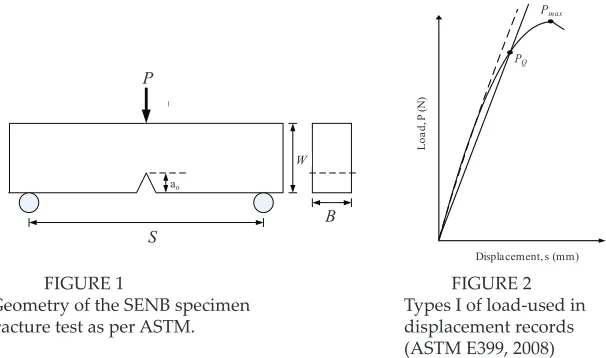
The specimen used for fracture toughness test was single edge notch bend (SENB or 3 point bending) specimen as shown in Fig. 1. Specimen geometry was selected according to ASTM E399 standard. The specimen was then polished with 500 to 1500 grit emery papers to obtain smooth surface. The pre-cracking was atained at pre-pre-cracking growth rates less than 10-8 m/cycle until the crack reaches half of the width of the specimen. Pre-cracking were carried
out on a pneumatic fatigue testing machine (14 kN maximum capacity). The
pre-cracking were performed at frequencies 10 Hz and using sinusoidal loading form. Stress ratio R=0.1 was applied in pre-cracking procedure at room temperature. The pre-cracking was performed at a constant ΔK level to obtain constant crack growth rate. The stress intensity factor value for SENB specimen was calculated according to the following equations:
Δ
ISSN: 2180-1053 Vol. 4 No. 2 July-December 2012
Plane Strain Fracture Toughness Determination for Magnesium Alloy
47
Displacement, s (mm)
L
Geometry of the SENB specimen Types I of load-used in fracture test as per ASTM. displacement records
(ASTM E399, 2008)
A secant line through the origin with slope of 95% of the initial elastic loading slope was used to determine the conditional maximum load value. For validation
of maximum fracture load Pmax, the principle type of load displacement record
as shown Fig. 2 was used for comparison as recommended by ASTM E399. To identify the validity of the plane strain fracture toughness value, Eq. (3) was referred. Here, a is a crack length, B is the minimum thickness that produces
a condition where plastic strain energy at the crack tip is minimal, KC is the
fracture toughness of the material and σy is the yield stress. σ
3.0 reSult anD DiScuSSion
Figure 3 showed the load-displacement curves for 2, 4, 6, 8 and 10 mm
thickness specimens. All displacement curves exhibited type I
load-displacement record as shown in Fig. 2. PQ is determined to be the valid value of maximum fracture load for calculation of fracture toughness. The mode-1 stress intensity factor at fracture KQ was calculated using Eq. (1) based on the PQ value obtained. The calculated values in Table 1 were then ploted in a KC
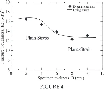
versus thickness relation curve as shown in Fig. 4. The results showed that the
highest KC value obtained was 16.5 MPa√m for 2 mm thickness specimen. The value of KC became relatively constant at about 13 MPa√m when the specimen
thickness exceeds 8 mm. This value was then considered as the plane strain
fracture toughness KIC of AZ61 magnesium alloy. The shear lip ratio value for validation of KΙC is below 0.1 (Anderson, 2005). The shear lip ratio for 8 and 10
mm specimen thickness were 0.1 and 0.08, respectively. Therefore, plane strain
ISSN: 2180-1053 Vol. 4 No. 2 July-December 2012 Journal of Mechanical Engineering and Technology
48
TABLE 1
Fracture toughness value for diferent thickness of magnesium alloy
⎟⎟⎠
Stress Plane-Stress
Plane-
Load-displacement curve for 2, 4, 6, 8 and 10 mm thickness of AZ61 magnesium alloy.
Specimen thickness, B (mm)
Fr
ISSN: 2180-1053 Vol. 4 No. 2 July-December 2012
Plane Strain Fracture Toughness Determination for Magnesium Alloy
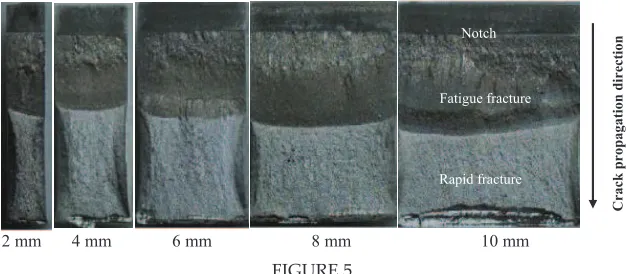
49 Macroscopic observation of fracture surfaces of the specimens clearly showed two discrete regions. These two distinct regions are shown in the optical micrograph of Fig. 5. The boundaries of these regions are well distinguished between the fatigue fracture region and rapid fracture region. The direction of the crack propagation was clearly determined. The fatigue crack initiated from
the notch and propagated parallel on both side. The fatigue fracture region
indicated the gradual crack propagation due to fatigue while the rapid fracture region with shinning appearance shows the unstable crack propagation and
characterized by fast crack features. For 8 and 10 mm thickness samples, the
fracture surface of the fatigue fracture region looks rough and shiny with
limited shear lip zone. This indicates that the plane strain conditions are achieved. For 2, 4 and 6 mm thickness samples the rapid fracture region looks
rough and shiny with large amount of shear lip zone which indicated that the samples were fracture in plane stress condition.
152
Specimen thickness, B (mm)
Fr
Overview of fracture surface for sample 2 mm, 4 mm, 6 mm, 8 mm and 10 mm.
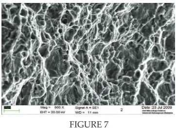
Figure 6 shows the fracture surface of 2 mm and 8 mm thickness samples ater fracture toughness test. The images were taken from the middle of sample thickness. Figure 6(a) showed the fracture surface of 2 mm thickness sample were relatively rough feature with the presence of many ductile dimples which may resulted from shear loading. Overview of the fracture surface revealed that almost half of fracture area was dominated by shear lip. Detail observation of the shear lip area is shown in Fig. 7. It is suggested that plastic zone size developed during the loading of 2 mm thickness sample was very
big. For plain strain fracture toughness validation, the plastic zone size should
ISSN: 2180-1053 Vol. 4 No. 2 July-December 2012 50
153 (b)
(a)
FIGURE 6
SEM observation on fracture surface in the middle of tested samples
FIGURE 7
SEM observation on the shear lip area of the tested sampes.
SEM observation on fracture surface in the middle of tested samples
FIGURE 6
SEM observation on fracture surface in the middle of tested samples
153 FIGURE 6
SEM observation on fracture surface in the middle of tested samples
FIGURE 7
SEM observation on the shear lip area of the tested sampes.
SEM observation on fracture surface in the middle of tested samples
FIGURE 7
SEM observation on the shear lip area of the tested
Figure 6(b) showed cleavage fracture surface associated with river patern was observed dominated the fracture surface of 8 mm thickness sample. This shows that the sample was failed in britle manner with limited plastic
deformation. Small ratio of shear lip area validates the sample fracture in plain strain condition.
4.0 concluSion
Plain strain fracture toughness of AZ61 magnesium alloy was investigated. Based on the results obtained, the indings are concluded as follows:
1. Fracture toughness value, KC for AZ61 magnesium alloy decreased
with the increasing of specimen thickness. The KC value became relatively constant at the specimen above 8 mm.
2. The critical plane strain fracture toughness, KΙC of extruded AZ61
ISSN: 2180-1053 Vol. 4 No. 2 July-December 2012
Plane Strain Fracture Toughness Determination for Magnesium Alloy
51 5.0 acKnoWleDgementS
The author would like to thank Prof. Dr. Y. Mutoh of Nagaoka University
of Technology, Japan for supplying the magnesium alloy and Faculty of Mechanical Engineering, Universiti Teknikal Malaysia Melaka for providing infrasture and supporting for this research.
6.0 reFerenceS
ASTM E399-06. 2008. Standard Test Method for Linear Elastic Plane Strain Fracture Toughness KIC of Metallic Materials.
B.L. Mordika and T. Ebert. 2001.Magnesium. Properties-applications-potential. Material Science and Engineering. A302. pp. 37-45.
Dufy. 1996. Magnesium Alloy: The light choice for aerospace. Materials World. pp.
127-133.
S. Schumann and H. Friedrich. 2003. Current and Future Use of Magnesium in the
Automobile Industry. Material Science Forum. Vol 419-422. pp. 50-51.
S. Hidetoshi and M. Toshji. 2005. Efect of texture on fracture toughness in extruded
AZ31 magnesium alloy. Scripta Materialia. 53. pp. 541-545.
S. Barbagallo and E. Cerri. 2004. Evaluation of the KIC and JIC fracture parameter in a sand cast AZ91 magnesium alloy. Engineering Failure Analysis. 11. pp. 127-140.
T. L. Anderson, PhD. 2005. Fracture mechanics, fundamental and application. 2nd ed.,