453
Experimental Evaluation of Performance of Different Thermal Boxes Heated by
Solar Radiation for Hot Water Storage System
Yuhazri, M.Y.
1, Kamarul, A.M.
1, Rahimah, A.H.
1, Haeryip Sihombing
1, Yahaya, S.H.
1, Maslan, M.N.
1,
and Hairul Effendy, M.2
Yuhazri, M.Y., Kamarul, A.M., Rahimah, A.H., Haeryip Sihombing, Yahaya, S.H., Maslan, M.N., and Hairul Effendy, M.
1Faculty of Manufacturing Engineering, 2Faculty of Engineering Technology,
Universiti Teknikal Malaysia Melaka, Durian Tunggal, 76100 Melaka, Malaysia Phone: +606-3315869, Fax: +606-3316411, Email: [email protected]
Abstract – The aim of this research is to investigate the performance of different thermal boxes heated by solar radiation for a water storage system that can be used in accordance with the climate of Asia-Pacific countries. In general, this research is related to thermal efficient water heating system, specifically to improve the water heating system that exists nowadays. The focus is to improve the thermal efficiency by adding different thermal boxes as the absorber bed. By implementing the black body and radiation concept, the air trapped in the box is heated. The trapped air then increases the collisions between the molecules and directly increases the temperature inside the box, higher than the outside environment. Based on theory and concept purposed, the temperature of the water increases more efficient and faster by using radiation heat as the source. Based on 24 hours experimental results revealed steel thermal box is better to be used for tropical weather like Malaysia.
Keywords – Thermal boxes, solar radiation, water storage, thermal efficient, absorber bed.
I. INTRODUCTION
A solar collector is commonly used for water heating system. There are many inventors that came up with their design to improve the efficiency of the thermal water heater [1-3]. This is because the opportunities of this technology to grow are wide open. The source for this technology is the sun, which is a utopian fuel, limitless, ubiquitous and clean. These are the main causes that attracted many researchers to investigate and develop this technology wider. There are many researchers tried to optimize the usage of solar energy such as Lindblad et al., [4], Hammer et al., [5], Reim et al., [6] and Trillat-Berdal et al., [7].
As known, the source from the sun light is limitless and clean but in order to use this kind of source, there are many optimizations needed to be done on the system to make it more efficient. The theory on transferring the heat from the sun light is well known and is usually a famous topic to be discussed about. This is clearly proven when researchers such as Velraj et al., [8], Mettawee and Assassa [9] and Jaisankar et al., [10] attempted to improve the efficiency of the solar water heating system. The less energy usage for the water heater becomes the main reason for many researchers to keep improving the system in order to
replace conventional water heater [11-13]. This is because the energy that is required to heat the water is higher than cooling the water. Therefore, by using solar as an energy source for heating the water, the use of electricity for the heating process can be replaced.
Thus, the thermal hot water system needs to be redesigned in order to improve the efficiency of the thermal conductivity to produce heat that is equal to the heat generated by the electricity energy. In this research, a thermal box material is proposed to improve the thermal hot water system efficiency by considering Malaysia weather conditions.
II. MATERIALS, METHOD & PROCEDURES
Materials used to produce the collector is determined and selected by CES Edu Pack (2010) software system. This software was used to select the material based on the attribute that is needed for the product. In this case, the thermal attribute of the material is the most important part to be determined and then followed with the cost of the material. Based on CES, steel and the galvanize iron are the materials that have the highest solar radiation absorption. Therefore, the materials are selected as the main material for the thermal box. For heat pipe characteristic, copper is chosen due to its high thermal conductivity. Table 1shows the component of the product and the material that has been chosen.
Table 1. List of material for hot water system. Component of the product Material
Heat pipe Copper Thermal box (body) Steel
Galvanize Iron Thermal box (top) Steel
Galvanize Iron Transparent top cover Glass Connector slot Copper
Tank PVC
Pipe PVC
The materials were selected depending on their function and cost of the raw material. Material for the component such as pipe, connector, lip boundaries and etc are selected by the thermal insulator characteristic. This product is iDECON 2012 – International Conference on Design and Concurrent Engineering
454 related to the heat; therefore the thermal expansion of the material characteristic is usually an issue. In order to overcome the problem, the selected materials are required to resist high temperature to avoid the deformation from happening.
In this experimental research, selected material efficiency was tested to fabricate the thermal box. There are a few things that need to be controlled to make sure the experiment goes smoothly. The variables in this research are time of the testing, material of the component, dimension of the product, design of the product, and flow rate of the water. In order to differentiate the efficiency of the thermal box, the experiment was conducted by evaluating both conditions. First is evaluated without the thermal box and the other evaluated with the thermal box. By comparing the result, the more efficient system can be determined.
The control experiment is conducted as reference for the other experiment that is held. This experiment is held at a room temperature. The room temperature remains constant 18 C, 22 C, and 26 C. The purpose of this experiment is to evaluate the temperature changes in a control environment. The experiment was held at Universiti Teknikal Malaysia Melaka. The testing duration started from 7.00 am till 6.00 am (24 hours). The materials used in the experiment are steel and galvanize iron. Figure 1 depicted the schematic experiment setup.
Fig. 1. Schematic experiment setup.
III. III. RESULTS & DISCUSSION
In this research, the proposed thermal water heaters are tested in 24 hours per testing. There are 5 tests that were held for each setup. The testing was held in Malacca during a sunny day. There are three main different setups of thermal water heaters that were tested in this project which is control experiment, thermal box at daytime and thermal box at night.
A.Daytime Analysis
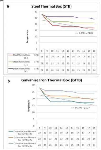
The experiments were held in an air-conditioned room. This is because the ambient temperature is controlled to get the reading for the efficiency of the thermal box. The duration of the control experiment is 10 hours (a daytime only). It started from 8 am to 6.00 pm. There are three different surrounding temperatures that were tested. There are two types of thermal box tested. The material used is steel for the thermal box 1 and galvanized iron for the thermal box 2.
By using steel as the material for the thermal box, control experiments are made to determine the relationship between the material and temperature ambient. Based from the reading measured by using a thermometer, the initial temperature drops and starts to maintain following the ambient temperature. The slope for the graph is y = -0.790x + 24.01 as shown in Figure 2(a). The galvanize Iron as the material for the thermal box show that the gradient is higher. The initial temperature of the water source is 28 °C for both boxes. The temperature drops according to the surrounding temperature. This shows that the thermal box is sensitive with the temperature changes of the surrounding. The Figure 2(b) shows slope for the graph is y = -0.727x + 23.27. The gradient of STB is higher than GITB because the temperature drop in STB is high.
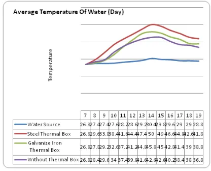
455 Figure 3 shows the average temperature of the water source increased at 7.00 am until 2.00 pm, so, the average temperature of water also increased. At 2.00 pm until 7.00 pm, the average temperature of water source started to decrease, therefore the average temperature of water also decreased. The temperature drop is caused by the decreasing environment temperature. It showed that the average temperature of water at 2.00 pm is high.
Fig. 3. The average of water temperature at daytime.
The steel thermal box has a higher average temperature than galvanized iron thermal box. Based on the graph, the temperature started at a same point which is 26.8 °C average. The steel absorbs more energy to heat the water due to the highest temperature reach on it. Thus, when the temperature starts to drop, the temperature is still higher than the galvanized iron thermal box.
The peak hour is determined based on the highest point of the temperature in a whole day. Based on the reading from the graph, the peak hour is at a range of 2.00 pm until 4.00 pm. The temperatures are measured during the day based on situation which are Steel Thermal Box, Galvanized Iron Thermal Box and without Thermal Box as shown in Table 2.
Table 2: The peak hours average temperature.
Time
Peak Hours Average Temperature Steel Thermal
Box
Galvanized Iron Thermal Box
Without Thermal Box in out in Out in out 02.00 50 50.2 45.8 45.6 42.6 42.6 02.15 50 50.4 45.6 45.4 42.6 42.6 02.30 50.4 50.2 45.8 45.2 42.8 42.4 02.45 49.6 49.2 45 45 42.6 42.6 03.00 49 48.4 45 44.4 42.6 42.2 03.15 48.6 48.6 44.8 44.2 41.6 41.4 03.30 48.4 47 44.2 43.8 41.4 41 03.45 47.6 46.8 43.6 43.2 40.8 40.8 04.00 46.6 46.6 42.8 42.8 40.2 40.6
The percentage of temperature difference is more during the day because there is the presence of the sun. However, as the sun goes down, so does the temperature because the temperature could not be contained since the surrounding temperature during night time is cold. There are the temperature changes in the percentage of readings for each experiment which is done by using steel thermal box, galvanized iron thermal box and without thermal box. The thermal box temperature changes percentage is very high at the extreme temperature especially for steel and galvanized iron thermal box. The highest temperature changes percentage that was achieved for the thermal box is 64.47 % at 2.00 pm which is represented by steel thermal box. It is followed by the galvanized iron thermal box that has a difference in temperature percentage which is 53.42 % at 1.00 pm. However, the average temperature without using the thermal box is higher than the average temperature of its water source. This is because the surrounding temperature is very low, which results in the high percentage of average temperature drop. Based on the calculation, zero is also found as the value of temperature changes. This is because the environment temperature has achieved the equilibrium. This clearly shows that the temperature of the water source is the same as the water that was tested in the experiment. Therefore, when the surrounding temperature is cold, it releases the temperature and drops it until the equilibrium temperature is achieved.
The efficiency of the thermal water heater is calculated based on the peak hour data. This is because; the efficiency of the water heater is more suitable to be calculated during the highest performance of the thermal water heater. From calculation show the efficiency of the thermal box achieved 70 % above. Therefore, the thermal box is efficient and shows the mechanism of preheating the water by using the concept is efficient and can be utilized. The data used for calculating the efficiency is in the range of 2 pm until 4 pm.
B.Night Analysis
The duration of night analysis is 12 hours started from 7 am until 7.00 pm. Steel is used as the thermal box due to the highest solar radiation factor. Based on the graph in Figure 4(a) shows that recorded the temperature changes during the testing held, the highest temperature that can be reached by using steel thermal box is 45°C at night. The temperature started decreasing from 7.00 pm until 5.00 am and started to maintain at 7.00 am. At the end of the test, the temperature of the steel thermal box is around 27°C until 28°C. The overall comment on the data shows that the temperature decreased due to the temperature drop of the ambient temperature. This is because the heat released for the tank storage is based on the heat equilibrium mechanism [14,15].
456 and started to maintain until 7.00 am. At the end of the test, the temperature without using thermal box is around 26 °C until 27 °C. This shows that the temperature is released during the experiment held. There are many factors that caused this mechanism to occur such as the surrounding temperatures drop, the storage failed to contain the heat longer and the heat equilibrium mechanisms.
Fig. 4. Night temperature for (a) steel thermal box, (b) galvanize thermal box and (c) average temperature for the boxes.
Contrast to the experiment without using the thermal box, the reading decreased from 7.00 pm until 1.00 am, then increased and decreased, but still maintained around 26 - 29°C until 7.00 am as shown in Figure 4 (c). When the average temperature is very high, the percent of average temperature drop is also high. This is because when the surrounding temperature is cold, it will release the heat and drop it until the equilibrium temperature is achieved [16,17]. The steel thermal box has a higher average temperature than galvanized iron thermal box. Based on that statement, the higher temperature can be achieved, the more it can last.
C.Overall Performance
The duration of gathering the data started from 7.00 am until 6.00 am. The percentage of temperature difference is more during the daytime because there is the presence of the sun. However, as the sun goes down, so does the temperature because the temperature could not be contained since the surrounding temperature during night time is cold. There are the temperature changes in the percentage of readings for each experiment which is done by using steel thermal box, galvanized iron thermal box and without thermal box. The thermal box temperature changes percentage is very high at the extreme temperature especially for steel and galvanized iron thermal box. Figure 5 shows the highest temperature changes percentage that was achieved for the thermal box is 64.47 % at 2.00 pm which is represented by steel thermal box. It is followed by the galvanized iron thermal box that has a difference in temperature percentage which is 53.42 % at 1.00 pm.
Fig. 5. Thermal box temperature difference percentage for 24 hours.
457 percentage of average temperature drop. Based on the calculation, 0 is also found as the value of temperature changes. This is because the environment temperature has achieved the equilibrium. This clearly shows that the temperature of the water source is the same as the water that was tested in the experiment. Therefore, when the surrounding temperature is cold, it releases the heat and drops it until the equilibrium temperature is achieved. By comparing the energy usage for the electrical water heater with the thermal water heater, the thermal water heater is more energy saving since it has zero usage of electricity. This is because the water is preheated by using the surrounding temperature and the radiation from the solar.
IV. SUMMARY
Based on the experiment carried out, the steel thermal is better compared to the other due to several reasons. The steel thermal works in term of its high efficiency and also the temperature. This refers to it having a different efficiency in which it is efficient and retains the warm temperature even though there is an absence of the thermal box. When the sun is at its peak, the steel thermal produces a higher temperature compared to the other materials. When the sun sets and night falls, the surrounding temperature becomes cold and the water temperature drops. However, the steel thermal’s water temperature is still warmer than the other materials. Thus, it basically refers back to the materials that are used in carrying out the experiment.
ACKNOWLEDGMENT
The authors gratefully acknowledged to Universiti Teknikal Malaysia Melaka for the financial support under short term grant, PJP/2011/FKP(2A)/S00869.
REFERENCES
[1] W. Xiaowu, H. Ben, Exergy analysis of domestic-scale solar water heaters, Renewable and Sustainable Energy Reviews. 9 (2005) 638-645.
[2] V.V. Tyagi, N.L. Panwar, N.A. Rahim, R. Kothari, Review on solar air heating with and without thermal energy storage system, Renewable and Sustainable Energy Reviews. 16 (2012) 2289-2303. [3] J. Wu, Z. Yang, Q. Wu, Y. Zhu, Transient behaviour and dynamic
performance of cascade heat pump water heater with thermal storage system, Applied Energy. 91 (2012) 187-196.
[4] P. Lindblad, P. Lindberg, P. Oliveira, K. Stensjo, T. Haidorn, Design, engineering, and construction of photosynthetic microbial cell factories for renewable solar fuel production, AMBIO: A Journal of the Human Environment. 41 (2012) 163-168.
[5] A. Hammer, D. Heinemann, C. Hoyer, R. Kuhlemann, E. Lorenz, R. Muller, H.G. Beyer, Solar energy assessment using remote sensing technologies, Remote Sensing of Environment. 86 (2003) 423-432. [6] M. Reim, A. Beck, W. Körner, R. Petricevic, M. Glora, M. Weth, T.
Schliermann, J. Fricke, C. Schmidt, F.J. Pötter, Highly insulating aerogel glazing for solar energy usage, Solar Energy. 72 (2002) 21-29.
[7] V. Trillat-Berdal, B. Souyri, G. Fraisse, Experimental study of a ground-coupled heat pump combined with thermal solar collectors, Energy and Buildings. 38 (2006) 1477-1484.
[8] R. Velraj, R.V. Seeniraj, B. Hafner, C. Faber, K. Schwarzer, Heat transfer enhancement in a latent heat srorage system, Solar Energy. 65 (1999) 171-180.
[9] E.S.B. Mettawee, G.M.R. Assassa, Thermal conductivity enhancement in a latent heat storage system, Solar Energy. 81 (2007) 839-845.
[10] S. Jaisankar, T.K. Radhakrishnan, K.N. Sheeba, Experimental studies on heat transfer and friction factor characteristics of thermosyphon solar water heater system fitted with spacer at the trailing edge of twisted tapes, Applied Thermal Engineering, 29 (2009 1224-1231.
[11] C. Seligman, J.M. Darley, Feedback as a means of decreasing residential energy consumption, Journal of Applied Psychology, 62 (1977) 363-368.
[12] B.J Huang, C.P Lee, Long-term performance of solar-assisted heat pump water heater, Renewable Energy. 29 (2004) 633-639. [13] J.R.B. Ritchie, G.H.G. McDougall, J.D. Claxton, Complexities of
Household Energy Consumption and Conservation, Journal of Consumer Research. 8 (1981) 233-242.
[14] M.C. Lin, L.J. Chun, W.S Lee, S.L. Chen, Thermal performance of a two-phase thermosyphon energy storage system, Solar Energy. 75 (2003) 295-306.
[15] A. Dogan, Y. Kaplan, T.N. Veziroglu, Numerical investigation of heat and mass transfer in a metal hydride bed, Applied Mathematics and Computation. 150 (2004) 169-180.
[16] L.L. Lacy, M.B. Robinson, T.J. Rathz, Containerless undercooling and solidification in drop tubes, Journal of Crystal Growth. 51(1981) 47-60.
458
Experimental Study on Effect of Reflector Bed Designs Heated by Direct Solar
Radiation for Hot Water Storage System
Yuhazri, M.Y.
1, Kamarul, A.M.
1, Rahimah, A.H.
1, Haeryip Sihombing
1, Yahaya, S.H.
1, Samat, K.F.
1and
Izamshah, R.
1Yuhazri, M.Y., Kamarul, A.M., Rahimah, A.H., Haeryip Sihombing, Yahaya, S.H., Samat, K.F., and Izamshah, R.
1Faculty of Manufacturing Engineering,
Universiti Teknikal Malaysia Melaka, Durian Tunggal, 76100 Melaka, Malaysia Phone: +606-3315869, Fax: +606-3316411, Email: [email protected]
Abstract – The aim of this research is to investigate the performance of different reflector bed design heated by direct solar radiation for a water storage system that can be used in accordance with the climate of Malaysia country. In general, this research is related to thermal efficient water heating system, specifically to improve the water heating system that exists nowadays. The focus is to improve the thermal efficiency by adding different absorber bed designs. Based on experimental results shown the temperature of the water increases more efficient and faster by using the curve reflector bed. energy can be trapped more efficiently dependent upon the type of solar collectors used. Each type of solar thermal collector is designed to absorb the shorter wavelengths of light which are received from the sun (0.3-2µm in length) but prevent heat wavelengths (2-10µm in length) from escaping by utilizing the greenhouse effect then delivers radiant energy either directly or indirectly to a hot water storage tank. There are many inventors that came up with their design to improve the efficiency of the thermal water heater [1-3]. This is because the opportunities of this technology to grow are wide open. The source for this technology is the sun, which is a utopian fuel, limitless, ubiquitous and clean. These are the main causes that attracted many researchers to investigate and develop this technology wider. There are many researchers tried to optimize the usage of solar energy such as Lindblad et al., [4], Hammer et al., [5], Reim et al., [6] and Trillat-Berdal et al., [7].
Flat plate collectors have been extensively studied by Hottel and Woertz [8], Bliss [9], Nahar and Garg [10], Francken [11]. Flat plate collectors are either corrugated Mathur et al., [12], bond duct, Patil [13] or tube-in-plate type [14] with different clamping arrangements Yellot and Sobotka [15], Gupta and Garg [16], Bliss [9]. The performance of the flat plate collector depends upon various design parameters, such as the number of covers, type and thickness of glazing Whillier [17], the type of
coating on the collector plate Nahar and Garg [18], spacing between the collector and the inner glass Nahar and Garg insulation material Hollands [22], Nahar et al., [23] and the type of insulation used Whillier and Saluja [24], all of which are responsible for the performance of a flat plate collector. There are several other operational parameters, such as the mass flow rate of fluid, solar radiation, inlet temperature, ambient temperature, wind speed, sky conditions, dust deposition on glass cover Nahar and Gupta [25], which also affect the collector performance
The evacuated-tube collectors is referred to the absorber strip is located in an evacuated and pressure proof glass tube. The heat transfer fluid flows through the absorber directly in a U-tube or in countercurrent in a tube-in-tube system. Several single tubes, serially interconnected, or tubes connected to each other via manifold, make up the solar collector. A heat pipe collector incorporates a special fluid which begins to vaporize even at low temperatures. The steam rises in the individual heat pipes and warms up the carrier fluid in the main pipe by means of a heat exchanger. The condensed liquid then flows back into the base of the heat pipe [26]. The pipes must be angled at a specific degree above horizontal so that the process of vaporizing and condensing functions. There are two types of collector connection to the solar circulation system. Either the heat exchanger extends directly into the manifold in wet connection or it is connected to the manifold by a heat-conducting material at dry connection. A dry connection allows to exchange individual tubes without emptying the entire system of its fluid. Evacuated tubes offer the advantage that they work efficiently with high absorber temperatures and with low radiation [27]. Higher temperatures also may be obtained for applications such as hot water heating, steam production, and air conditioning.
The concentrators collector This article is not included in your organization's subscription. However, you may be able to access this article under your organization's iDECON 2012 – International Conference on Design and Concurrent Engineering
459 agreement with Elsevi is a new principle for collecting and concentrating solar energy, the ideal cylindrical light collector, has been invented. This development has its origins in detecting Cherenkov radiation in high energy physics experiments [28]. In its present form, the collector is a trough like reflecting wall light channel of a specific shape which concentrates radiant energy by the maximum amount allowed by phase space conservation as mentioned by Winston [29].
The principle behind heat pipe's operation is actually very simple. The heat pipe is hollow with the space inside evacuated, much the same as the solar tube. In this case insulation is not the goal, but rather to alter the state of the liquid inside. Inside the heat pipe is a small quantity of purified water and some special additives. At sea level water boils at 100 oC, but if you climb to the top of a mountain the boiling temperature will be less that 100oC. This is due to the difference in air pressure.
As known, the source from the sun light is limitless and clean but in order to use this kind of source, there are many optimizations needed to be done on the system to make it more efficient. The theory on transferring the heat from the sun light is well known and is usually a famous topic to be discussed about. This is clearly proven when researchers such as Velraj et al., [30], Mettawee and Assassa [31] and Jaisankar et al., [32] attempted to improve the efficiency of the solar water heating system. The less energy usage for the water heater becomes the main reason for many researchers to keep improving the system in order to replace conventional water heater [33-35]. This is because the energy that is required to heat the water is higher than cooling the water. Therefore, by using solar as an energy source for heating the water, the use of electricity for the heating process can be replaced.
Thus, the thermal collector bed for hot water system needs to be redesigned in order to improve the efficiency of the thermal conductivity. In this research, an appropriate thermal collector bed is proposed to improve the thermal efficiency of heating pipe by considering Malaysia weather conditions.
II. MATERIALS, METHOD & PROCEDURES
The experiments conducted using three different methods of design in the thermal collector bed for water storage system. Those three methods will be name it as method I, II and III.
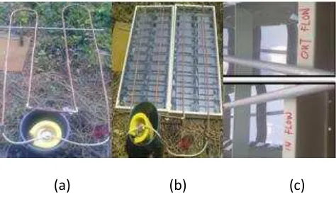
The first method is set up by using a copper heating pipe without the reflector bed as shown in Figure 1 (a). The second method is using copper heating pipe with the flat reflector bed on heating pipe as depicted in Figure 1 (b). The Figure 1 (c) shows the third method is using copper heating pipe with the curve reflector.
The experimental setup consists of two dimensionally similar solar collectors set same location and can be tilted to a predetermined angle through a mechanical system. It consists of two modules, the collector module and the
control system module. The collector module consists of the absorber, glazing reflector, insulation, back and front casing and copper water heating pipe to assemble these components. The control system module consists of a water pump, of maximum up to 450 L/h, 6.5 watt, control system, heat sensor and two temperature views (Environment & water tank thermometer).
(a) (b) (c)
Fig. 1. Schematic experiment setup for methods (a) I, (b) II, (c) III.
The measured variables in this experiment include the inlet and outlet air temperature, ambient temperature and total energy transfer into water tank. The collectors are instrumented with two unit thermometer sensor for measuring the inlet and outlet temperatures of the collector exit point. The ambient temperature is measured using an infrared thermometer around the absorbed bed from direct sunlight. The same facility design of water flow and size heating pipe calibrated to assure accurate comparison. The thermometer sensor is amplified the final result of the total heat in water.
All the copper pattern collector has diameter 12 mm of flow pipe and total length of the flow design leading to a flow passage area is 700 cm. Normal mirror is used as the reflector for both methods of collectors (flat and curve). But in this case study, the reflector of absorber rests on a stainless steel flat plate (high reflection surface) of the collector, whereas the stainless steel flat plate is lifted above the casing supports to create and fix the flow design of water. Heat insulation is provided to prevent heat loss of the water temperature as well as into the tank. Closed loop water inlets and outlets are used to distribute the flowing water uniformly throughout the collector and keep warm in the tank. Design data for the three methods of absorber bed are shown in Table 1.
460
Table 1. Design data for three methods.
Details Method I Method II Method III Heating pipe
material Copper Copper Copper Diameter of heating
pipe 12 mm 12 mm 14 mm Thickness of
heating pipe 0.5 mm 0.5 mm 1.0 mm Total length of
water flow
6λ0 cm ≤ 700
cm
6λ0 cm ≤ 700
cm
6λ0 cm ≤ 700
cm Reflector Base No Yes Yes Collector tilt ≠10° ≠10° ≠10° Tank capacity 2 Liter 2 Liter 2 Liter Tank insulation Foam rubber Foam rubber Foam rubber Qmax of water
pump 450 l/h 450 l/h 450 l/h
The collectors are warmed up and run at least 30 minuts before tests are conducted. The collector slope is adjusted to ≠10 degree, which is considered suitable for the geographical location of Malaysia. Before starting the performance tests, the collectors with their respective settings are tested for leaks under the operating pressure. Figure 2 shows the complete system design, which is changer only at plate refector for all the testing methods.
Fig. 2. The complete system design of the experimental.
III. RESULTS & DISCUSSION
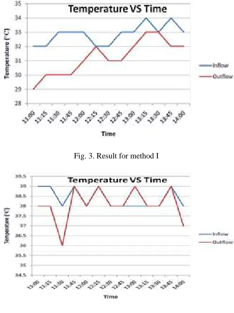
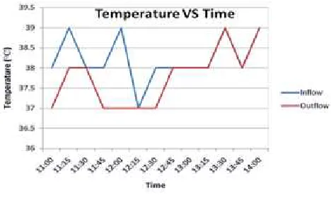
In Method I, only one independent set of experiments is conducted to investigate the performance totalheatof both inlet and outlet point of collectors. Result from the data shown that temperature of inflow water always higher then outflow temperature.
Figure 3 shows the inflow and outflow temperature based on time for Method I. The temperature of outflow always lower than inflow water is because the effect of the ambient temperature during the experimentation. In this experiment, the average of ambient temperature is ±29°C. The temperatures between the heating pipe and ambient temperature are driving forces for heat transfer. The larger amount of temperature difference, the higher is the rate of heat transfer. Besides that,another issue of outflow
temperature always lower than inflow temperature because the heat loss at copper heating pipe. Without the reflector at absorber bed, the heat loss from copper heat pipe is higher. The result of experiment clearly shows that the experiment undergone without a reflector it is less efficient for the heat to transfer into the water.
The second experiment method is using copper heating pipe with the flat reflector on heating pipe. Figure 4 shows the inflow and outflow of temperature based on time for method II. The temperatures of inflow and outflow show similarities rate to certain extend. The performance of the absorber bed is higher when the average ambient temperature is same with Method I (±29°C). It shows that the reflector of absorber bed can minimized the heat loss between the heating pipe and ambient temperature. The concept of concentrating solar energy is provenworking in this experimentation. The reflector can maintain the inlet and outlet temperature constant very well if compare with Method I.
Fig. 3. Result for method I
461
Fig. 5. Result for method III
Figure 5 shows the inflow and outflow temperature based on time for Method III. Generally, thetemperature of inflow and outflow in Method III is similar with Method II. The result of Method III is showing thesame performance with Method II when the average of ambient temperature same with Method I (±29°C). In theoretical, the thermal conductivity of copper heating pipe is 401W/m°C
From experiment of method I, II and III, the results have shown thedifferencesin temperature in the storage tank. Figure 6 shows that the thermal efficiency increasedgraduallyin storage tank in three hours. In Method I, the increase of the temperature of water in storage tank increase to its maximum point which is about 36°C. At the same time, the temperature of Method II and III reached about 46°C. The existence of the reflector significantly influenced the heat level in the storage tank, because it even though the heat is dissipated from the heating pipe, but the reflector regenerate heat for the heating pipe by focusing the ray of sun onto the pipe thus reheating it to the maximum temperature yet sustaining the temperature of water in the pipe [38].
Fig. 6. Average water temperature in storage tank for three methods.
Three different methods with independent sets of experiments are conducted to investigate the performance of the total heat transfer into water. The first experiment of
method I is set up by using copper heating pipe without the reflector. The second experiment of method II is by using copper heating pipe with the flat reflector on heating pipe. The third experiment method is using copper heating pipe with reflector.
Fig. 7. Efficiency method for three methods.
Figure 7 shows the efficiency of the inlet and outlet temperature as well as the efficiency of the performance for each method of collector. The graph clearly shows that with the reflector it is more efficient than without the reflection plate over the entire range of mass flow rate considered [37]. This is because the efficiency of Method II and III is very high, average of efficiency performance is 99% and 98.60%. The lowest range of efficiency among the three methods is the Method I. The average efficiency of Method I only achieved 95.08%.
IV. SUMMARY
The purpose of the experiment undergone is to test and verify the performance of the absorber bed with the different method, which is method I, II and III. By instilling the principle of concentrators collector and evacuated-tube in the heating pipe application, it is shown successive thus allowing this novel design to apply for a patent of solar collector.
Experimental results have shown that this new concept have 4 % improvement in the thermal efficiency and an increase of about ±10°C temperature in the storage tank. Generally, the Method III absorber has a lower overall loss coefficient compared to the other considered types. This novel design of the copper collector lends itself as an economical and efficient alternative for known solar collectors.
462 ACKNOWLEDGMENT
The authors gratefully acknowledged to Universiti Teknikal Malaysia Melaka for the financial support under short term grant, PJP/2011/FKP(2A)/S00869.
REFERENCES
[1] W. Xiaowu, H. Ben, Exergy analysis of domestic-scale solar water heaters, Renewable and Sustainable Energy Reviews. 9 (2005) 638-645.
[2] V.V. Tyagi, N.L. Panwar, N.A. Rahim, R. Kothari, Review on solar air heating with and without thermal energy storage system, Renewable and Sustainable Energy Reviews. 16 (2012) 2289-2303. [3] J. Wu, Z. Yang, Q. Wu, Y. Zhu, Transient behaviour and dynamic
performance of cascade heat pump water heater with thermal storage system, Applied Energy. 91 (2012) 187-196.
[4] P. Lindblad, P. Lindberg, P. Oliveira, K. Stensjo, T. Haidorn, Design, engineering, and construction of photosynthetic microbial cell factories for renewable solar fuel production, AMBIO: A Journal of the Human Environment. 41 (2012) 163-168.
[5] A. Hammer, D. Heinemann, C. Hoyer, R. Kuhlemann, E. Lorenz, R. Muller, H.G. Beyer, Solar energy assessment using remote sensing technologies, Remote Sensing of Environment. 86 (2003) 423-432. [6] M. Reim, A. Beck, W. Körner, R. Petricevic, M. Glora, M. Weth, T.
Schliermann, J. Fricke, C. Schmidt, F.J. Pötter, Highly insulating aerogel glazing for solar energy usage, Solar Energy. 72 (2002) 21-29.
[7] V. Trillat-Berdal, B. Souyri, G. Fraisse, Experimental study of a ground-coupled heat pump combined with thermal solar collectors, Energy and Buildings. 38 (2006) 1477-1484.
[8] H.C. Hottel, B.B. Woertz, The performance of flate plate solar heat collectors, Trans. ASME. (1942) 91-104.
[9] R.W. Bliss, The derivations of several plate efficiency factors useful in the design of flate-plate solar heat collectors, Solar Energy. 3 (1959) 55.
[10] N.M. Nahar, H.P. Garg, Free convection and shading due to gap spacing between absorber plate and cover glazing in solar energy flate plate collector, Applied Energy. 7 (1980) 129-145.
[11] J.C. Francken, On the effectiveness of a flat plate collector, Solar Energy. 33 (1984) 363-369.
[12] K.N. Mathur, M.L. Khanna, T.N. Davey, S.P. Suri, Domestic solar water heater, J. Sci. Ind. Res. 18A (1959) 51-59.
[13] D.G. Patil, Field performance and operation of a flat-glass solar heat collector, Solar Energy. 17 (1975) 111-118.
[14] CSIRO, Solar water heater, Division of Mechanical Engineering, Circular No.2, Highett, (1964) Victoria.
[15] J.I. Yellot, R. Sobotka, An investigation of a solar water heater performance, Trans ASHRAE. 70 (1964) 425.
[16] C.L. Gupta, H.P. Garg, System design in solar water heaters with natural circulation, Solar Energy, 12 (1968) 163-182.
[17] A. Whillier, Plastic cover for solar collectors, Solar Energy. 7 (1963) 148-151.
[18] N.M. Nahar, H.P. Garg, Selective coatings on flat plate solar collectors, Renewable Energy Rev. J. 3 (1981) 37-51.
[19] C.K. Hsieh, R.W. Coldeway, Study of thermal radiative properties of antireflection glass for flat plate solar collector cover, Solar Energy, 16 (1974) 63-72.
[20] R.M. Winegarner, Heat-mirror – a practical alternative to the selective absorber, Proceeding of the conference of the American section of ISES and SES of Canada, Sharing the Sun. 6 (1976) 337-348.
[21] B.F. Simon, Solar collector performance evaluation with NASA-Lewis solar simulator – results for an evacuated tubular selectively coated collector with a diffuse reflector, NASA TMX 71695 (1975). [22] K.G.T. Hollands, Honeycomb devices in flat plate solar collectors,
Solar Energy. 9 (1965) 159-164.
[23] N.M. Nahar, R.H. Marshall, B.J. Brinkworth, Investigation of flat plate collectors using transparent insulation materials, Int. J. Solar Energy. 17 (1995) 117-134.
[24] A. Whillier, G. Saluja, The thermal performance of a solar water heater, Solar Energy. 9 (1965) 21-26.
[25] N.M. Nahar, J.P. Gupta, Effect of dust on transmittance of glazing materials for solar collectors under arid zone conditions of India, Solar and Wind Technology. 7 (1990) 237-243.
[26] I.A. Khatib, Harnessing solar energy to meet energy needs for water desalination in Gaza strip, Journal of Applied Sciences in Enviromental Sanitation. 3 (2008) 117-125.
[27] S.V. Masson, M. Qu, D.H Archer, Performance modeling of a solar driven absorption cooling system for Canegie εellon University’s intelligent workplace, Proceeding of the 6 International Conference for Enhanced Building Operations, Shenzhen, China (2006) 1-13. [28] W.R. Leo, Techniques for nuclear and particle physics experiments
– a how – to approach, 2nd Rev. (1994) Springer-Verlag.
[29] R. Winston, Principles of solar concentrators of a novel design, Solar Energy. 16 (1974) 89-95.
[30] R. Velraj, R.V. Seeniraj, B. Hafner, C. Faber, K. Schwarzer, Heat transfer enhancement in a latent heat srorage system, Solar Energy. 65 (1999) 171-180.
[31] E.S.B. Mettawee, G.M.R. Assassa, Thermal conductivity enhancement in a latent heat storage system, Solar Energy. 81 (2007) 839-845.
[32] S. Jaisankar, T.K. Radhakrishnan, K.N. Sheeba, Experimental studies on heat transfer and friction factor characteristics of thermosyphon solar water heater system fitted with spacer at the trailing edge of twisted tapes, Applied Thermal Engineering, 29 (2009 1224-1231.
[33] C. Seligman, J.M. Darley, Feedback as a means of decreasing residential energy consumption, Journal of Applied Psychology, 62 (1977) 363-368.
[34] B.J Huang, C.P Lee, Long-term performance of solar-assisted heat pump water heater, Renewable Energy. 29 (2004) 633-639. [35] J.R.B. Ritchie, G.H.G. McDougall, J.D. Claxton, Complexities of
Household Energy Consumption and Conservation, Journal of Consumer Research. 8 (1981) 233-242.
[36] [36] ASHRAE, Methods of Testing to Determine Thermal Performance of Solar Collectors, ASHRAE STANDARD 93-77, ASHRAE, 345 East 47th street, New York, (1977) NY 10017. [37] [37] P.H. Sung, J.D. Lin, R.H. Shiu, C.Y. Chen, C.Y. Lin, M.D.
Lin, Energy saving benefit analysis of green construction using energy-efficient lighting equipment, Applied Mechanics and Materials. 178-181 (2012) 24-28.