STUDY CASE ON SIMULATION AN ACTIVE FILTER BASED
ON LOAD DC MOTOR
Musa Yusup Lada1, Ismadi Bugis2and Md Hairul Nizam Talib3
1
UTeM/FKE, Durian Tunggal, Melaka. Email: [email protected]
2
UTeM/FKE, Durian Tunggal, Melaka.
3
UTeM/FKE, Durian Tunggal, Melaka.
A
BSTRACTNowadays power system facing serious problem with power quality in terms of power factor and harmonics due to increasingly number of nonlinear load. This paper will discuss about the effecting of dc motor by using an active filter on the power system. The simulation had been done by using MATLAB/ Simulink. The Voltage source shunt active filter (VSAF) has been used in this simulation with the common DC bus. The p-q theorem will be used to control the PWM switching of the active filter. Simulation result shows that by using a Series DC motor as load on active filter the line current will compensate and reduce the THD of the line current.
Key words: Series DC Motor, VSAF, Shunt Active Filter, THD, Instantaneous Power Theory
I
NTRODUCTIONNonlinear load such as DC Motor feet through three phase rectifier generate harmonic current and voltage in power system. Effect of the nonlinear load on power system such as low power factor, increase losses, reduces the efficiency of the power system and increase the total harmonics distortion. Before this there were used LC filter to eliminate harmonics current, and as the result LC filter can only eliminated the high frequency of THD. The Serious problem occurs for nonlinear load for harmonics came from the low frequency. To overcome these problems, for many years, several of techniques and topologies
were developed. Eq. (1) and eq. (2) are shown the equation for Total Harmonic Distortion of voltage (THDv) and Total
Harmonic Distortion of current (THDi)[1], [2], [3], [6].
1 2
100 V V
THDV h (1)
1 2
100 I
I
THDi h (2)
World Engineering Congress 2010, 2nd– 5thAugust 2010, Kuching, Sarawak, Malaysia Conference on Engineering and Technology Education
Figure 1: Shunt active power filter
The series DC motor has its armature and field connected in a series circuit as shown in figure 2. The series motor is able to deliver this high starting torque due to the fact that its field is operated below saturation. Torque Series DC Motor is proportional to the square of the current (below field saturation) and it makes that series DC Motor produces more torque per ampere of current than others DC Motor [3]. The series DC motor is used where the load requires a high breakaway torque such as locomotive, crane, or oil drilling rig applications.
Figure 2: Series DC Motor
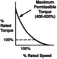
The starting torque developed by a series motor can be as high as 500 percent of its full load torque rating. Therefore, an increase in load will result in an increase in both armature and field current as shown in figure 3. As a result the armature flux and field flux increase together. Since the torque developed in a DC motor is dependent upon the interaction of armature and field fluxes, torque increases by the square of the value of current increase. Therefore, a series motor will yield a greater torque increase than a shunt motor for a given increase in current which is will make more distortion on three phase AC supply. If the load on the motor is reduced the current flowing in both the armature and the field circuits is reduced causing a reduction in their flux densities, it mean that series DC Motor have a serious problem with line current due increasing the load continually.
Refer to figure 2, the mathematical for series DC motor shows in eq. 3 by applying the Kirchoff’s voltage rule.
e
O
IR
V
V
(
)
(3)Where:
Vo = Power supply (Volts)
I = Current (A)
R = Terminal Resistance (Ohms)
Ve = Back EMF (Volts)
The back EMF generated by the motor is directly proportional to the angular velocity of the motor as shows in eq. 4. The proportionality constant is the back EMF constant of the motor.
e
e
k
V
(4)Where:
w = angular velocity of the motor
ke= back EMF constant of the motor
Therefore, the voltage supply for series DC motor can be rewritten
)
(
)
(
eO
IR
k
V
(5)S
HUNTA
CTIVEP
OWERF
ILTERC
ONFIGURATIONThe shunt active power filter configuration is based on pulse with modulation inverter. There were two types of active power filter which is voltage source active filter (VSAF) as shown if figure 4 and current source active filter (CSAF). The difference between VSAF and CSAF is the DC bus, which is the VSAF use capacitor as a DC-bus while the CSAF use inductance as a DC-bus. The basic principle of the active filter is to generate a current equal and opposite in polarity to the harmonic current drawn by the load and it will injecting to the load for forcing the source current to be in sinusoidal waveform.
World Engineering Congress 2010, 2nd– 5thAugust 2010, Kuching, Sarawak, Malaysia Conference on Engineering and Technology Education
The switching strategy of an active power filter was develop by akagi in 1983 knows as p-q theory. eq. (6) and eq. (7) shows the transformation concept as algebra transformation in order to get the active power and reactive power three phase are shown in eq. (8) and eq. (9).
c b a o i i i i i i 2 1 2 1 2 1 2 3 2 3 0 2 1 2 1 1 3 2 (6) c b a o v v v v v v 2 1 2 1 2 1 2 3 2 3 0 2 1 2 1 1 3 2 (7) o o
i
v
i
v
i
v
p
(8)
i
v
i
v
q
(9)
The p-q theory state that the real active power and imaginary power can be separated into two parts and the equation is shows
in eq. 10 and eq. 11. The
p
andq
are the average power due to component actual current of p and q respectively whilep
~
and
q
~
are the oscillating power due to component actual current of p and q.Real Power,
p
p
p
~
(10)Imaginary Power,
q
q
q
~
(11)In loss free situation, the shunt APF need to provide any active power (real power) to cancel the reactive and harmonic currents from the load. These currents show up as reactive power. Thus it is indeed possible to make the DC-bus capacitor delivers the voltage and this reactive power demanded by the active power filter. As the reactive power comes from the DC-bus and this reactive energy transfers between the load and the DC-DC-bus capacitor which is charging and discharging of the
DC-capacitor, the average DC-bus voltage can be maintained at a prescribed value. The DC-bus PID control strategy
Figure
M
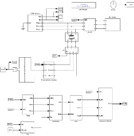
ODELINGDC M
OTORSeries DC motor is used in this simulation and shows in figure 6. PI controller varies alpha taking at 15º. Three phase AC power supply that 20A output current DC motor will be maintain rectifier.
S
IMULATIONR
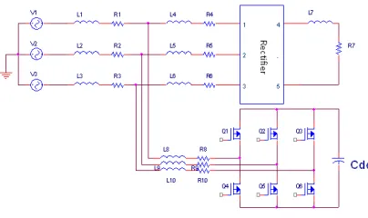
ESULTThe simulation of an active filter with DC diagram as shown in figure 7. There were four power filter, AC to DC converter and DC motor DC motor load. This simulation used 240V 50Hz three
Three Phase Supply
Figure 7: Block diagra
Figure 5: DC-bus PID control strategy
simulation and using PI controller to control the DC Motor current varies alpha of thyristor until motor current matches to reference
supply will convert to DC supply using controlled three phase maintained constant thereby controlling the firing angle of a
Figure 6: Modeling DC Motor
with DC motor load had been done using MATLAB/simulink were four main parts in this simulation which are three phase DC motor as load test. Figure 8 shows the block diagram of MAT 240V 50Hz three phase power supply and 5kW DC motor as a lo
AC/DC Three
Phase Supply
Active Filter
DC MOTOR
ck diagram of an active power filter with DC motor load
current maintained at 20A as reference current. Pulse width is phase rectifier, this to ensure angle of a controlled three phase
World Engineering Congress 2010, 2nd– 5thAugust 2010, Kuching, Sarawak, Malaysia Conference on Engineering and Technology Education
Figure 8: Simulink active power filter with DC motor load
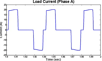
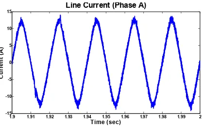
Figure 9 illustrated the three phase line voltage supply. Figure 10 shows the three phase load current. The load current will remain in 20Amp peak current in order to maintain the DC current that will supply to DC motor via AC to DC converter. The three phase active filter current shows in figure 11, which is will injected to the line supply to compensate the load current. As a result after injected three phase active filter to line supply, the three phase line current will became sinusoidal as shown in figure 12.
Figure 9: Three phase Line voltage
Figure 10: Three phase load current
1.9 1.91 1.92 1.93 1.94 1.95 1.96 1.97 1.98 1.99 2 -250
-200 -150 -100 -50 0 50 100 150 200 250
Time (sec)
V
o
lt
a
g
e
(
V
)
Three Phase Line Voltage
1.9 1.91 1.92 1.93 1.94 1.95 1.96 1.97 1.98 1.99 2 -25
-20 -15 -10 -5 0 5 10 15 20 25
Time (sec)
C
u
rr
e
n
t
(A
)
Figure 11: Three phase active filter current
Figure 12: Three phase line current
For more clear view result, single phase waveform was taken as shown in figure 13, figure 14 and figure 15.
Figure 13: Load current (Phase A)
1.9 1.91 1.92 1.93 1.94 1.95 1.96 1.97 1.98 1.99 2 -30
-20 -10 0 10 20 30
Three Phase Active Filter Current
Time (sec)
C
u
rr
e
n
t
(A
)
1.9 1.91 1.92 1.93 1.94 1.95 1.96 1.97 1.98 1.99 2 -15
-10 -5 0 5 10 15
Three Phase Line Current
Time (sec)
C
u
rr
e
n
t
(A
)
1.9 1.91 1.92 1.93 1.94 1.95 1.96 1.97 1.98 1.99 2 -25
-20 -15 -10 -5 0 5 10 15 20 25
Load Current (Phase A)
Time (sec)
C
u
rr
e
n
t
(A
World Engineering Congress 2010, 2nd– 5thAugust 2010, Kuching, Sarawak, Malaysia Conference on Engineering and Technology Education
Figure 14: Active filter current (Phase A)
Figure 15: Line current (Phase A)
The series DC motor current shows in figure 16. By controlling the PI controller for DC motor, as a result the DC motor current will remain constant at 20A. Figure 17 shows the DC voltage supply to DC motor from AC to DC converter.
Figure 16: Armature current of DC motor
1.9 1.91 1.92 1.93 1.94 1.95 1.96 1.97 1.98 1.99 2 -30
-20 -10 0 10 20 30
Active Filter Current (Phase A)
Time (sec)
C
u
rr
e
n
t
(A
)
1.9 1.91 1.92 1.93 1.94 1.95 1.96 1.97 1.98 1.99 2 -15
-10 -5 0 5 10 15
Line Current (Phase A)
Time (sec)
C
u
rr
e
n
t
(A
)
0 0.2 0.4 0.6 0.8 1 1.2 1.4 1.6 1.8 2 0
5 10 15 20 25
Time (sec)
C
u
rr
e
n
t
(A
)
Figure 17: Voltage source of DC motor
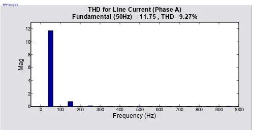
The THD for load current in phase A show in figure 18. The effectiveness of non-linear load which is in this case was DC motor make the THD of current load is above the required by quality standards IEEE-519. After injecting the active filter the THD of current will reduce from 42.86% to 9.27%. The THD for line current shows in figure 18.
Figure 18: THD for load current (Phase A)
Figure 18: THD for line current (Phase A)
0 0.2 0.4 0.6 0.8 1 1.2 1.4 1.6 1.8 2 0
50 100 150 200 250 300
Time (sec)
V
o
lt
a
g
e
(
V
)
Voltage Source of DC Motor
0 100 200 300 400 500 600 700 800 900 1000
0 2 4 6 8 10 12
Frequency (Hz) THD for Load Current (Phase A) Fundamental (50Hz) = 12.58 , THD= 42.86%
M
a
g
0 100 200 300 400 500 600 700 800 900 1000 0
2 4 6 8 10 12
Frequency (Hz) THD for Line Current (Phase A) Fundamental (50Hz) = 11.75 , THD= 9.27%
M
a
World Engineering Congress 2010, 2nd– 5thAugust 2010, Kuching, Sarawak, Malaysia Conference on Engineering and Technology Education
C
ONCLUSIONActive power filter are useful to eliminated the harmonics that generated by the nonlinear load. In this case, modeling DC motor is use to analyzes the effected of DC Motor as a load on active power filter system. The modeling of DC motor is use with close loop PI controller to make sure that the current that flow though DC motor will in constant value, in this case the DC motor current constant at 20A. The effectiveness of active power filter on the DC motor load is good dynamic and steady-state response compare to use a LC filter in others words active filter can make a better quality of power system. Refer to the simulation result, the active power filter can compensated the load current so that the load current become more sinusoidal or less harmonics distortion.
REFERENCE
[1] A. Emadi, A. Nasiri, and S. B. Bekiarov, “Uninterruptible Power Supplies and Active Filter”, Florida, 2005, pp.
65-111.
[2] Hanny H. Tumbelaka, Lawrence J. Borle, Chem V. Nayar and Seong Ryong Lee, “A Grid Current-controlling Shunt
Active Power Filter”, The 7thInternational Conference on Power Electronics, Oct 2007.
[3] Moinuddin K Syed and Bv Sanker Ram, “Instantaneous Power Theory Based Active Power Filter: A
MATLAB/Simulink Approach”, Journal of Theoretical and Applied Information Technology, 2005-2008.
[4] Samir Mehta and John Chiasson, “Nonlinear Control of a Series DC Motor: Theory and Experiment”, IEEE Trans.
Ind. Electronics, vol. 45, No. 1, Feb 1998.
[5] Hasan A. Yousef and Hanan M. Khalil, “A Fuzzy Logic-Based Control of Series DC Motor Drives”, Proceedings
of the IEEE International Symposium on Industrial Electronics, vol. 2, Jul 1995.
[6] Moleykutty George and Kartik Prasad Basu, “Modeling and Control of Three-Phase Shunt Active Power Filter”,
American Journal of Applied Scinces 5 (8), 2008.
[7] Hirofumi Akagi, “Control Strategy and Site Selection of a Shunt Active Filter for Damping of Harmonic
Propagation in Power Distribution Systems”. 1997.
[8] Changqing Cai, Liping Wang and Guohui Yin, “A Three-Phase Power Filter Based on Park Transformation”, 2009.
[9] Taruna Jain, Shailendra Jain and Ganga Agnihotri, “Comparison of Topologies of Hybrid Active Power Filter”,
2007.
[10] Rafael Ordonz, Roberto Morales and Charif Karimi, “Three-Phase Active Power Filter under Non-Sinusoidal
Voltage Conditions”, 2009.
[11] Auzani Jidin, Jurifa Mat Lazi,Abd Rahim Abdullah,Fazlli Patkar,Aida Fazliana Abd Kadir and Mohd Ariff Mat
Hanafiah, “Speed Drive Based on Torque- Slip Characteristic of the Single Phase Induction Motor”,PEDS 2005.
[12] Zhao wei, Luo an, Peng Jianchun, Deng Xia and Peng ke, “A New Hybrid Active Power Filter for Harmonic