DESIGN OF SLOTTED MEANDER LINE ANTENNA WITH PROBE FEED METHOD FOR ISM BAND APPLICATION
NUR AISHAH BINTI ZAINUDDIN
This report is submitted in partial fulfillment of the requirements for the award of Bachelor of Electronic Engineering (Telecommunication Engineering) With
Honours
Faculty of Electronic and Computer Engineering Universiti Teknikal Malaysia Melaka
ii
UNIVERSTI TEKNIKAL MALAYSIA MELAKA
FAKULTI KEJURUTERAAN ELEKTRONIK DAN KEJURUTERAAN KOMPUTER
BORANG PENGESAHAN STATUS LAPORAN
PROJEK SARJANA MUDA II
Tajuk Projek : Design of Slotted Meander Line Antenna With Probe Feed Method for ISM Band Application
Sesi
Pengajian : 1 1 / 1 2
Saya NUR AISHAH BINTI ZAINUDDIN . mengaku membenarkan Laporan Projek Sarjana Muda ini disimpan di Perpustakaan dengan syarat-syarat kegunaan seperti berikut:
1. Laporan adalah hakmilik Universiti Teknikal Malaysia Melaka.
2. Perpustakaan dibenarkan membuat salinan untuk tujuan pengajian sahaja.
3. Perpustakaan dibenarkan membuat salinan laporan ini sebagai bahan pertukaran antara institusi pengajian tinggi.
4. Sila tandakan ( √ ) :
SULIT* *(Mengandungi maklumat yang berdarjah keselamatan atau kepentingan Malaysia seperti yang termaktub di dalam AKTA RAHSIA RASMI 1972)
TERHAD** **(Mengandungi maklumat terhad yang telah ditentukan oleh organisasi/badan di mana penyelidikan dijalankan)
TIDAK TERHAD
Disahkan oleh:
__________________________ ___________________________________ (TANDATANGAN PENULIS) (COP DAN TANDATANGAN PENYELIA)
iii
“I, hereby declare that this thesis entitled, Design of Slotted Meander Line Antenna with Probe Feed Method for ISM Band Application is a result of my own research idea
concept for works that have been cited clearly in the references.”
iv
“I, hereby declare that I have read this report and in my opinion this report is sufficient in terms of scope and quality for the award of Bachelor of Electronic Engineering
(Telecommunication Electronics) with Honours.”
SIGNATURE : ………
SUPERVISOR’S NAME : MOHAMAD ZOINOL ABIDIN B. ABD AZIZ
v
vi
ACKNOWLEDGEMENT
In the name of Allah, The Most Gracious and The Most Merciful. All the praises and thanks be to Allah, The Lord of the ‘Alamin for the strengths and His blessing in completing this thesis. This dissertation would not have been possible without the guidance and the help of several individuals who in one way or another contributed and extended their valuable assistance in the preparation and completion of this study.
First and foremost, my utmost gratitude to Mr. Zoinol Abidin B. Abd Aziz, my Project Supervisor whose sincerity and encouragement had helped me to survive until the end of this project.No words could describe how meaningful it is to work and to be taught by one of the most dedicated lecturer I have ever met.
My colleagues and staff in the Faculty of Electronic and Computer Engineering, especially the Telecommunication Electronics Departments for the use of facilities in the Microwave and PSM Lab and for consultations given.
vii
ABSTRACT
viii
ABSTRAK
ix
CONTENTS
CHAPTER TITLE PAGE
PROJECT TITLE
REPORT STATUS VERIFICATION FORM STUDENT’S DECLARATION SUPERVISOR’S DECLARATION DEDICATION ACKNOWLEDGEMENT ABSTRACT ABSTRAK
TABLE OF CONTENTS LIST OF FIGURES
LIST OF ABBREVIATION AND SYMBOLS LIST OF TABLES
i ii iii iv v vi vii viii ix xiii xvii xix
I INTRODUCTION
1.0 Introduction 1.1 Problem Statement 1.2 Objective
1.3 Scope of Project 1.4 Methodology 1.5 Thesis Outline
1 1 2 3 3 3 4
II LITERATURE REVIEW
2.0 Introduction
2.1 Wireless Communication System 2.2 Antenna
2.3 Antenna Properties 2.3.1 Input Impedance
2.3.2 VSWR and Return Loss 2.3.3 Bandwidth
x
2.3.4 Radiation Pattern 2.3.5 Polarization
2.3.6 Gain 2.3.7 Directivity 2.4 Types of Antenna
2.4.1 Microstrip Patch Antenna 2.4.2 Coplanar Waveguide (CPW) 2.4.3 Planar Antenna
2.4.3.1 Planar Inverted-L and Inverted-F Antenna
2.4.3.2 Planar Monopole Antenna 2.4.3.3 Planar Meander Line Antenna 2.4.4 Meander Line Antenna
2.4.4.1 Uniform and Non-Uniform Meander Line Antenna
2.4.4.2 Taper Meander Line Antennas 2.4.4.3 Back-to-Back Meander Line Antennas
2.4.5 Slot Antenna 2.5 Feeding Methods
11 13 13 14 14 14 17 19 20 22 22 23 24 25 26 27 30
III SLOTTED MEANDER LINE ANTENNA DESIGN
3.0 Introduction
3.1 Design Specifications
3.2 Parametric Studies On Design of Slotted Meander Line Antenna
3.2.1 Rectangular Microstrip Patch Antenna 3.2.2 Parametric Studies: Number of Turn, N 3.2.3 Parametric Studies: Location of Slotted
Meander Line
3.2.4 Parametric Studies: Number And Location of Slotted Meander Line
xi
3.3 Design Parameter 3.4 Design Process
3.4.1 Design of Microstrip Meander Line Patch Antenna
3.4.2 Design of Monopole Meander Line Antenna 3.4.3 Design of Microstrip Slotted Meander Line Antenna
3.5 Simulation Process 3.6 Fabrication Process 3.7 Measurement Process
3.7.1 Return Loss Measurement 3.7.2 Radiation Pattern Measurement
41 42 42 43 44 48 52 54 54 55
IV RESULTS AND DISCUSSION
4.0 Introduction
4.1 Design of Microstrip Meander Line Antenna and Slotted Meander Line Antenna
4.2 Design of Rectangular Microstrip Patch Antenna 4.3 Parametric Studies: Number of Turn of Slotted
Meander Line Antenna
4.4 Parametric Studies: Number of Slotted Meander Line 4.5 Parametric Studies: Number and Location of Slotted
Meander Line Antenna
4.5.1 Result Analysis of 2 Slots of Slotted Meander Line Antenna
4.5.2 Result Analysis of 3 Slots of Slotted Meander Line Antenna
4.5.3 Result Analysis of 6 Slots of Slotted Meander Line Antenna
4.5.4 Result Analysis of 7 Slots of Slotted Meander Line Antenna
4.5.5 Result Analysis of 8 Slots of Slotted Meander Line Antenna
4.5.6 Result Analysis of 12 Slots of Slotted Meander Line Antenna
xii
4.6 Design Comparison and Analysis 77
V CONCLUSION AND SUGGESTION
5.0 Conclusion 5.1 Future Work
79 79 80
REFERENCES
APPENDIX A
81
xiii
LIST OF FIGURES
NO TITLE PAGE
1.1 2.1
Project Flow
Industrial, Scientific And Medical (ISM) Band Range
5 7 2.2
2.3
The Range Of Bandwidth Normalized Power Patterns
10 12 2.4 Radiation Pattern and 3dB Beamwidth 13 2.5
2.6
Physical Structure of Microstrip Antenna
Dimension View And Prototype Of Microstrip Meander Line Antenna
15 17
2.7 Structure of Coplanar Waveguide 18
2.8 Conductor Backed Co-Planar Waveguide 18 2.9 Geometry of A Narrow-Strip Monopole With A Horizontal Bent
Portion And Monopole
21
2.10 Geometry of the PIFA 21
2.11 Geometry of The Planar Monopole Antenna With A Trident-Shaped (Three-Branch) Feeding Strip.
22
2.12 Geometry of Planar Meander Line Antenna For Triple-Band Mobile Phone Antennas With The Microstrip Line Feeding Technique.
23
2.13 Meander Line Structure 24
2.14 Uniform Meander Line And Non-Uniform Meander Line Antenna 25 2.15 Taper Meander Line Antennas; Ascendant, Side-Fed Descendant,
Centrally Fed Descendant
26
2.16 Structure of Back-To-Back Meander Line Antenna 27
2.17 Rectangular Slot 27
xiv
Asymmetry L Slots
2.19 Photograph And Schematic Of Folded Meander Line Slot Antenna 29
2.20 Slotted Meander Line Antenna 30
2.21 2.22 2.23 2.24 2.25 2.26 3.1 3.2 3.3 3.4 3.5 3.6 3.7 3.8 3.9 3.10 3.11 3.12 3.13 3.14 3.15 3.16 3.17 3.18
Slotted Meander Line Antenna Structure Inset Feed Edge Feed Probe Feed Proximity-Coupled Patch Aperture-Coupled Patch Project Methodology
Design Drawing of Rectangular Microstrip Patch Antenna Probe Feed Location at Rectangular Microstrip Patch Antenna Slotted Meander Line Antenna Structure with Different Number of Turns
Slotted Meander Line Antenna Structure with Different Position of Slotted Meander Line
Slotted Meander Line Antenna Structure with Different Number of Slotted Meander Line
Slotted Meander Line Antenna Structure with Different Number of Turns and Locations
Design Parameter of Slotted Meander Line Antenna Microstrip Meander Line Antenna
Front and Back View of Monopole Meander Line Antenna Structure of Microstrip Antenna
Slotted Meander Line Antenna – Design 1 Slotted Meander Line Antenna – Design 2 Slotted Meander Line Antenna – Design 3 Slotted Meander Line Antenna – Design 4 Slotted Meander Line Antenna – Design 5 Slotted Meander Line Antenna – Design 6 Slotted Meander Line Antenna – Design 7
xv 3.19 3.20 3.21 3.22 3.23 3.24 3.25 3.26 3.27 3.28 3.29 4.1 4.2 4.3 4.4 4.5 4.6 4.7 4.8 4.9 4.10 4.11 4.12 4.13 4.14 4.15 Background Properties FR-4 Material for Substrate
Structure of Probe Feed Connector Design of Waveguide Port
Boundary Conditions Settings Monitor Settings
Summarization of Simulation Process Summary of Fabrication Process Summary of Measurement Process Return Loss Measurement Setup Radiation Pattern Measurement Setup
Return Loss for Microstrip Meander Line Antenna and Slotted Meander Line Antenna
Rectangular Microstrip Patch Antenna
Simulated and Measured Return Loss for Rectangular Microstrip Patch Antenna
Radiation Pattern of Rectangular Microstrip Patch Antenna Simulated E-Field Radiation Pattern of Rectangular Microstrip Patch Antenna
Simulated H-Field Radiation Pattern of Rectangular Microstrip Patch Antenna
Graph of Gain, Resonant Frequency, Directivity and Return Loss vs. Number of Turn
Structure of Different Number of Slotted Meander Line Antenna Resonant Frequency of Different Number of Slotted Meander Line Different Number and Location of Slotted Meander Line Antenna Simulated and Measured Return Loss for Design 1
Simulated E-Field Radiation Pattern of Design 1 Simulated H-Field Radiation Pattern of Design 1 Measurement Radiation Pattern of Design 1 Resonant Frequency and Return Loss of Design 2
xvi 4.16 4.17 4.18 4.19 4.20 4.21 4.22 4.23 4.24 4.25 4.26 4.27 4.28 4.29 4.30 4.31 4.32 4.33
Simulated E-Field Radiation Pattern of Design 2 Simulated H-Field Radiation Pattern of Design 2 Simulated and Measured Return Loss for Design 3 Simulated E-Field Radiation Pattern of Design 3 Simulated H-Field Radiation Pattern of Design 3 Measurement Radiation Pattern for Design 3 Simulated and Measured Return Loss for Design 4 Simulated E-Field Radiation Pattern of Design 4 Simulated H-Field Radiation Pattern of Design 4 Measurement Radiation Pattern for Design 4 Simulated Return Loss for Design 5 and Design 6 Simulated E-Field Radiation Pattern of Design 5 Simulated H-Field Radiation Pattern of Design 5 Simulated E-Field Radiation Pattern of Design 6 Simulated H-Field Radiation Pattern of Design 6 Resonant Frequency and Return Loss of Design 7 Simulated E-Field Radiation Pattern of Design 7 Simulated H-Field Radiation Pattern of Design 7
xvii
LIST OF ABBREVIATION AND SYMBOLS
RF - Radio Frequency
ISM - Industrial, Science and Medical (Band) CST - Computer Simulation Technology
FR-4 - Flame Retardant (Type 4 – made of woven glass reinforced epoxy resin)
UV - Ultra Violet
VSWR - Voltage Standing Wave Ratio PC - Personal Computer
Wi-Fi - Wireless Fidelity
ITU - International Telecommunication Union Zo - Characteristic Impedance
λg - Guide Wavelength
TEM - Transverse Electro-Magnetic Ɛreff - Effective Dielectric Constant Ɛr - Relative Dielectric Constant
L - Length of Patch Antenna W - Width Of Patch Antenna h - Height Of Patch Antenna
f - Frequency
c - Light Speed Constant d - Substrate Thickness
IEEE - Institute of Electrical and Electronic Engineers Std - Standard
CPW - Coplanar Waveguide
MIC - Microwave Integrated Circuits
xviii
PIFA - Planar Inverted-F Antenna RL - Return Loss
D - Directivity BW - Bandwidth
G - Gain
HPBW - Half Power Beam Width FNBW - First Null Beam Width
tan δ - Dielectric Loss / Tangent Loss µr - Permittivity
Wc - Copper thickness RCS - Radar Cross Section
N - Number of Turn AUT - Antenna Under Test
Sim. - Simulation Mea. - Measurement
dB - Decibel
xix
LIST OF TABLES
NO TITLE PAGE
3.1 Design Specifications of Slotted Meander Line Antenna 35 3.2 Design Material of Slotted Meander Line Antenna 35
3.3 Parameters Setup 49
3.4 Dimension of Probe Feed Layer 50
4.1 Simulation and Measurement Result of Rectangular Microstrip Patch Antenna
60
1
CHAPTER I
INTRODUCTION
1.0 Introduction
An antenna is a transducer that transmits or receives electromagnetic waves. In other words, antennas convert electromagnetic radiation into electrical current or vice versa. Antennas generally deal in a transmission and reception of radio waves and are a necessary part of all radio equipment. Based on another source, antenna is defined as an electrical conductor or system of conductors. Antenna can be used in two ways communication, transmitting and receiving. An antenna is a circuit element that provides a transition from a guided wave on a transmission line to a free space wave and it provides for the collection of electromagnetic energy [1].
2
atmosphere to its receiver with the same efficiency as it transfers energy from the transmitter into the atmosphere. Antenna characteristics are essentially the same regardless of whether an antenna is sending or receiving electromagnetic energy [2].
1.1 Problem Statement
The modernization of telecommunication system had brought many benefits to people nowadays. Previously people need to be at a specified place only to communicate with each other. For instance, people can only be connected or communicate using wired phone at home or public phone at certain places.
The need and trend to be in touch whenever and wherever they want has come to a huge demand of wireless devices with mobility and low profile to make the communication method and process become easier. Antenna is a crucial part of devices that allows the device itself to operate by transmitting and receiving signals. Small size device came with small size antenna. Therefore, for a compact device, a compact and low profile antenna that can operate at desired frequency range is needed.
There are many aspects need to be considered in designing an antenna. The problem that usually found in existing antennas is referred to the size of the antenna. Users prefer to have small size of device that can be carried anywhere without connected to wires.
Common design of antenna faced some issues regarding the size because a bigger size of antenna will not only make it costly, but also have difficulties to fit in a device. In order to overcome the problem, a meander line antenna would be one of the suitable methods to be used to design a low profile antenna. Meander line antenna is chosen because it is able to reduce or miniaturize the size of antenna. It is smaller in size and very flexible to be shifted or relocated [3].
3
meander line antenna due to the wide bandwidth characteristic that slotted antenna have.
1.2 Objective
The main objective of this project is to design, simulate and fabricate a slotted meander line antenna to be used at ISM band (2.4 – 2.5 GHz). It is designed to be smaller in size compared to existing antennas and consistently reducing the cost of design. The meander line antenna has been designed to operate at 2.4 GHz as it approaches the industrial, scientific and medical radio bands.
1.3 Scope of project
Firstly a meander line antenna will be designed specifically for ISM band application. The meander line technique is used to miniaturize the antenna and it will be slotted to get wider bandwidth.
The meander line antenna will be simulated with CST software to observe the result of antenna parameters such as return loss, bandwidth, gain, and directivity.
After that the antenna will be fabricated by using FR-4 board and chemical etching technique. The fabricated antenna will be measured to observe the result of return loss, bandwidth, gain and directivity of the antenna.
1.4 Methodology
4
designed antenna will be simulated to observe the antenna parameters such as return loss, bandwidth, gain and directivity.
Fabrication process will be done but before that, the antenna layout must be designed. As for material, FR-4 board will be used. UV Litography and chemical etching technique will be used to fabricate the antenna. A probe feed will be soldered to the antenna as a connector.
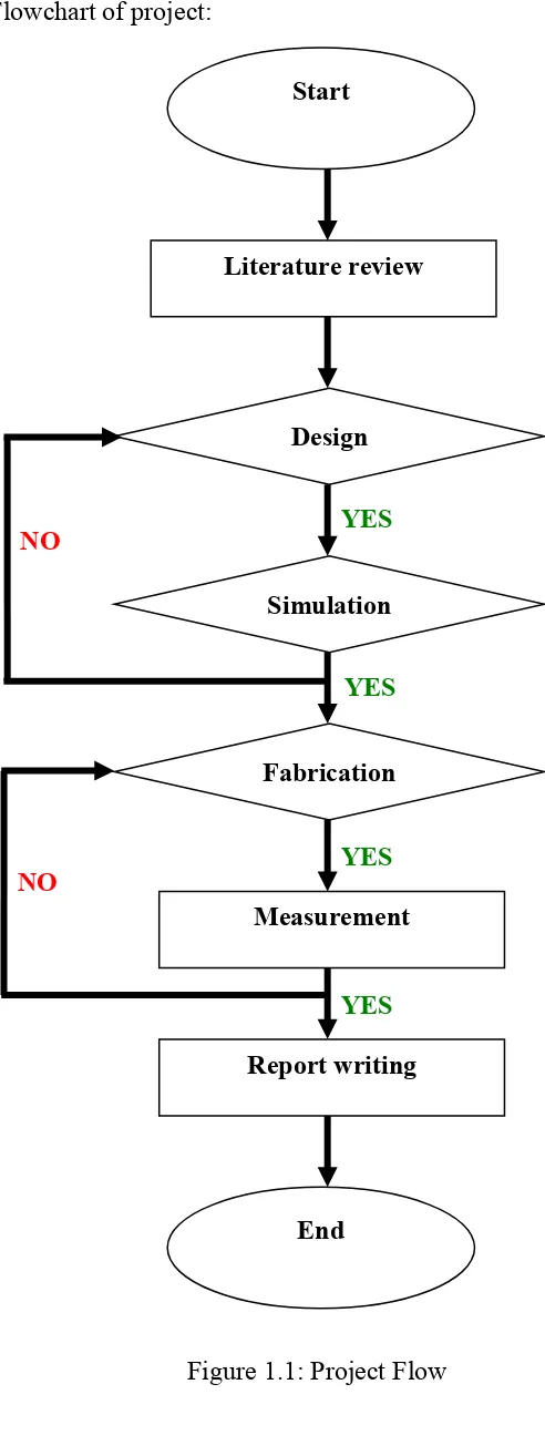
The fabricated antenna will be measured to observe the result of return loss, bandwidth, gain and directivity of the antenna. Report writing will be done to record all the results and discussions. Figure 1.1 below shows the overall flow of this project.
1.5 Thesis Outline
This thesis consists of five chapters describing all the work done in the project. The thesis outline is generally described as follows.
Chapter I of this report will cover the introduction of the project. Brief general background is presented and this chapter also includes the objective, scope of project and methodology. Chapter II will cover about literature review of antennas. For this purpose, the review is made by referring to many sources, mostly from related technical papers. Chapter III gives an overview of the antenna design methodology with the fundamental process in the design, simulate, fabricate and measurement procedures.
5
[image:24.595.137.383.73.730.2]Flowchart of project:
Figure 1.1: Project Flow Start
Report writing Fabrication
Simulation Design
Measurement Literature review
End
YES
YES
YES
YES
NO