Investigation of Minkowski Patch Antenna with
Meander Line Split Ring Resonator (ML-SRR)
Structure
1
H. Nornikman,
1B. H. Ahmad,
1M. Z. A. Abd Aziz,
2M. K. A. Rahim,
1A. R. Othman
1
Center for Telecommunication Research and Innovation (CeTRI), Faculty of Electronics and Computer Engineering, Universiti Teknikal Malaysia Melaka (UTeM), Melaka, Malaysia
2
Faculty of Electrical Engineering, Universiti Teknologi Malaysia, Johor, Malaysia
[email protected], [email protected], [email protected], [email protected], [email protected]
Abstract—The objective of this paper is to investigate the effect of the meander line split ring resonator on the modified Minkowski patch antenna. In this work, a modified Minkowski patch antenna with meander line split ring resonator (ML-SRR) and quadruple-P shaped split ring resonator (QPS-SRR) structure is presented. This proposed modified patch antenna with SRRs structures achieved remarkable 2.644 dB of gain at the frequency of 2.402 GHz compared to the normal Minkowski antenna without SRR structures with only 2.348 dB. This antenna had been simulated in the CST Microwave Studio simulation software.
Index Terms—Minkowski antenna, split ring resonator, metamaterial
I. INTRODUCTION
In recent years, there are many works to enhance the gain performance of the patch antenna design. The metamaterial or left-handed media (LHM) structure is one of the technique improve this problem. In 1968, Veselago had been proposed this technique by implementing split ring resonator (SRR) structure with metal wires [1]. Many researchers have studied patch antenna that adds this SRR structure, especially in wireless local area network (WLAN) range of 2.4 GHz. This paper had been investigating the effect of the meander line split ring resonator (ML-SRR) and the quadruple-P shaped split ring resonator (QPS-SRR) structure of the modified Minkowsi patch antenna. The parameters that are considered in this work are return loss, gain, directivity, and the radiation pattern of the patch antenna [2].
The geometry Fractal methods can include in many types such as Sierpinski carpet [3], Koch Fractal [4], Minkowski Fractal [5-6] Hilbert Fractal [7] and 3/2 Curve Fractal [8]. The Minkowski Fractal antenna is one popular technique to miniaturize the size of the patch antenna [9]. This Minkowski Fractal also can affect the multiband of frequency [10].
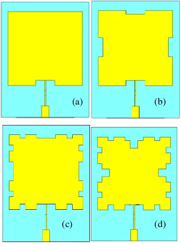
The Minkowski curve can be characterized by the iteration factor [11]. Zero iteration is represented by the normal patch without any scraped out of copper [12]. First iteration show
that four rectangular or square shape of copper had been cut from the patch, shown in Figure 1.
Figure 1. Modified Minkowski patch antenna iteration stage ; (a) Zero iteration; (b) First iteration; (c) Second iteration(d) Third iteration
II. PROPOSED SRR
Split ring resonators (SRRs) design is used to produce the negative dielectric constant (permittivity) and negative permeability [13]. From the previous work, this structure can increase the gain and miniaturize the size of the patch antenna and have the capability to improve the gain performance [14-15]. This SRR structure also has potential to increase the reflection loss performance of the pyramidal microwave absorber [16]. Figure 2 and Table I shows the proposed meander line split ring resonator (ML-SRR) while Figure 3 and
(a) (b)
Table II shows the Quadruple-P shaped split ring resonator (QPS-SRR). The dimension of the ML-SRR is 8.29 mm x 10.33 mm. The dimension of the larger QPS-SRR is 1.68 mm x 2.49 mm while the dimension of the smaller QPS-SRR is 1.37 mm x 2.03 mm.
Figure 2. Structure unit of meander line split ring resonator (ML-SRR) (a) normal condition SRR; (b) complimentary SRR condition
TABLE I. DIMENSION OF THE STRUCTURE UNIT OF MEANDER LINE SPLIT RING RESONATOR (ML-SRR)
Parameter part Dimension (mm)
A1 8.29
A2 10.33
Figure 3. Quadruple-P shaped split ring resonator (QPS-SRR); B1 = 1.68
mm, B2 = 1.37 mm, C1 = 2.49 mm, C2 = 2.03 mm (a) normal condition SRR;
(b) complimentary SRR condition
TABLE II. DIMENSION OF THE STRUCTURE UNIT OF QUADRUPLE-P
SHAPEDSPLIT RING RESONATOR (QPS-SRR)
Parameter part Dimension (mm)
B1 1.07
B2 1.29
C1 1.68
C2 0.76
III. PROPOSED ANTENNA
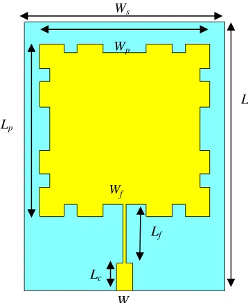
Minkowski Fractal shape based antenna is designed based on the bigger and smaller size of square shape generator [3]. Figure 4 and Table III shows the modified Minkowski patch antenna (without SRR structure added). This antenna uses FR-4 board substrates with dielectric constant of FR-4.3, tangent loss of 0.025, and thickness of 1.6 mm .
Figure 4. Modified Minkowski patch antenna (without SRR structure added)
TABLE III. DIMENSION OF THE MODIFIED MINKOWSKI PATCH ANTENNA
(WITHOUT SRR STRUCTURE ADDED)
Parameter part Dimension (mm)
Ws 34
Ls 45
Wp 28.86
Lp 28.86
Wf 0.5
Lf 9.95
Lc 4.55
Wc 2.81
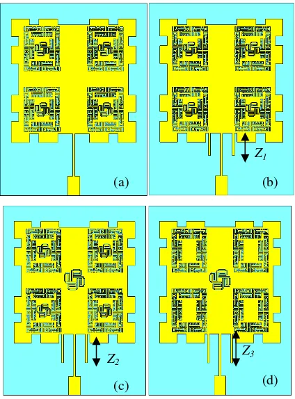
Figure 5 shows the different location of ML-SRR and QPS-SRR structure of the modified Minkowski patch antenna. Type A antenna had been representing the attached 4 pair of ML-SRR and QPS-SRR at the patch antenna to improve the gain performance. In Type B, a rectangular striplinehad been added to control the location of the resonant frequency of the antenna.
(a) (b)
(a) (b)
Wp
Lp
Wf
Lf
Lc
Wc Ws
Ls A2
C1
B1 A1
C2
Figure 5. Modified Minkowski patch antenna with different variation ; (a)Type A; (b) Type B; (c) Type C (d) Type D
For the Type C antenna, a larger version of QPS-SRR antenna had been added at the center location of patch antenna to enhance more gain of the antenna. In the Type D, 4 smaller versions of QPS-SRR had been removed from the design. Table IV shows the adjustment Stripline length to optimize the resonant frequency to 2.402 GHz
TABLE IV. THE ADDITION OF STRIPLINE TO ADJUST THE FREQUENCY RANGE TO 2.402GHZ
Minkowski Antenna type Rectangular strip length added (mm)
Figure 6 shows the return loss performance of the modified Minkowski patch antenna with ML-SRR and QPS-SRR (in different iteration stage). From the graph, it shows that, the different type of stage will control where is the resonant
frequency. The best reflection loss had been shown by second iteration of the Minkowski patch antenna. This antenna had been resonating at 2.402 GHz of frequency. The third iteration shows the worst return loss performance but it had been shifted from 2.402 GHz to the 2.202 GHz, the different frequency point of 200 MHz.
Return Loss of Modified Minkowski Patch Antenna with SRR
Frequency, GHz
Figure 6. Return loss performance of modified Minkowski patch antenna with ML-SRR and QPS-SRR (in different iteration stage)
Table V shows return loss, resonant frequency and the bandwidth of the Minkowski patch antenna. It shows that the second iteration Minkowski patch antenna had been achieved the best reflection loss with - 47.990 dB at a frequency of 2.402 GHz. The worst return loss performance had been achieved by third iteration by only - 14.665 dB but it has the wider bandwidth compared to the other iteration stage. This antenna (at third iteration stage) has a bandwidth of 100.7 MHz.
TABLE V. RETURN LOSS PERFORMANCE OF MODIFIED MINKOWSKI PATCH ANTENNA WITH ML-SRR AND QPS-SRR(IN DIFFERENT ITERATION
STAGE)
Third iteration 2.202 -14.665 100.7
TABLE VI. GAIN AND DIRECTIVITY PERFORMANCE OF MODIFIED
MINKOWSKI PATCH ANTENNA WITH ML-SRR AND QPS-SRR(IN DIFFERENT ITERATION STAGE)
Minkowski Antenna iteration stage
Gain (dB) Directivity (dBi)
Zero iteration 2.332 5.441
First iteration 2.495 5.505
Second iteration 2.348 5.539
Third iteration 0.775 5.434
Figure 7 and Table VII shows the resonant frequency, return loss and bandwidth of the different type of modified Minkowski patch antenna From the graph, it shows that the best performance of the return loss is the modified Minkowski patch antenna (without SRR structure) with – 47.999 dB at 2.402 GHz of frequency.
Return Loss of Different Type of Modified Minkowski Patch Antenna with SRR
Frequency, GHz
2.30 2.35 2.40 2.45 2.50 2.55
R
Figure 7. Return loss performance of the different type of modified Minkowski patch antenna with ML-SRR and QPS-SRR
TABLE VII. RETURN LOSS AND BANDWIDTH OF DIFFERENT TYPE OF
MINKOWSKI PATCH ANTENNA WITH SRR
Minkowski that in Type B antenna, it increases the gain of the Minkowski
patch antenna from the 2.348 dB to 2.644 dB. The addition of the rectangular stripline had been located back the resonant frequency from the 2.480 GHz at the Type A to 2.402 GHz in Type B antenna. This SRR structure did not give the big impact of the bandwidth performance.
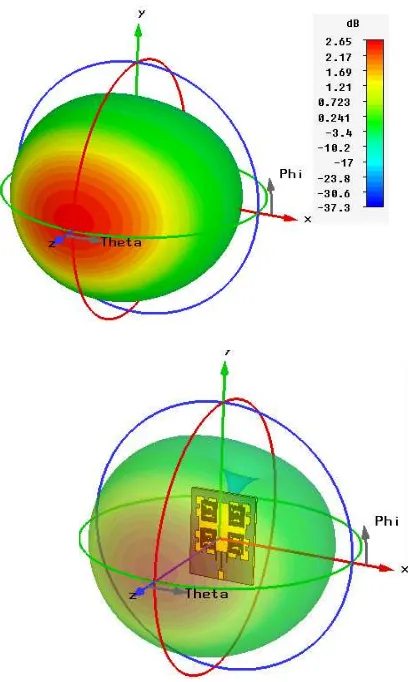
Figure 8 shows the 3D radiation pattern of the modified Minkowski antenna with SRR structure.Table VIII represents the gain and directivity performance of the different type of modified Minkowski patch antenna.
Figure 8. 3D radiation pattern of the antenna
TABLE VIII. GAIN AND DIRECTIVITY OF DIFFERENT TYPE OF MINKOWSKI PATCH ANTENNA WITH SRR
Minkowski Antenna type
Gain (dB) Directivity (dBi)
Without SRR 2.348 5.539
Type A 2.627 5.644
Type B 2.644 5.506
Type C 2.629 5.501
V. CONCLUSION
After simulation done, it shows that the gain had been enhanced by the addition of the ML-SRR and QPS-SRR on the modified Minkowski patch antenna. An improvement of the gain by 0.296 dB from 2.348 dB to 2.644 dB. The SRR has the capability can control the resonant frequency. The proposed antenna design can be integrated with RF transmitter [17] and RF receiver [18] to form a complete WLAN front-end system.
REFERENCES
[1] V. G. Veselago, “The Electrodynamics of Substances with Simultaneously Negative Values of Permittivity and Permeability,” Soviet Physics USPEKI, Vol. 10, no. 4, pp. 509 - 514, 1968.
[2] [x] H. A. Majid, M. K. A. Rahim, T. Masri, Left Handed Metamaterial Design For Microstrip Antenna Application, 2008 IEEE International RF and Microwave Conference, pp. 218-221, 2008
[3] [A] N. A. Saidatul, A. A. H. Azremi, R. B. Ahmad, P. J. Soh, and F. Malek, Multiband Fractal Planar Inverted F Antenna (F-Pifa) for Mobile Phone Application," Progress In Electromagnetics Research B, Vol. 14, pp. 127-148, 2009
[4] [B] A. Ismahayati, P. J., Soh, R. Hadibah, G. A. E. Vandenbosch, Design and Analysis of A Multiband Koch Fractal Monopole Antenna, 2011 IEEE International RF and Microwave Conference (RFM), pp. 58-62, 20111
[5] [C] F. Malek, H. Nornikman, M. S. Zulkefli, M. H. Mat, N. A. Mohd Affendi, L. Mohamed, N. Sudin, A. A. Ali, Complimentary Structure of Quadruple P-Spiral Split Ring Resonator (QPS-SRR) on Modified Minkowski Patch Antenna Design, 2012 IEEE Asia-Pacific Conference on Applied Electromagnetics (APACE 2012), pp. 142–147, 2012 [6] [c1] T. Masri, M. K. A. Rahim, M. N. A. Karim, A Novel 2D
Minkowski Gasket Electromagnetic Band Gap Structure for Multiband Microstrip Antenna, The Second European Conference on Antennas and Propagation (EuCAP 2007), pp. 1-4, 2007
[7] [D] V. Radonic, K. Palmer, G. Stojanovic, V. Crnojevic-Bengin, Flexible Sierpinski Carpet Fractal Antenna on a Hilbert Slot Patterned Ground, International Journal of Antennas and Propagation, vol. 2012, issue 4, pp. 1-7, 2012
[8] [E] S. Sadat, M. Fardis, G. Dadashzadeh, R. K. Baee, Proximity-Coupled Microstrip Patch Antenna Miniaturization using New Fractal
Geometry, 2005 IEEE International Symposium Antennas and Propagation Society, vol.3, pp. 3–8, 2005
[9] [F] J. K. Ali, A. S. A. Jalal, A Miniturized Multiband Minkowski-Like Pre-Fractal Patch Antenna for GPS and 3G IMT-2000 Handset, Asian Journal of Informantion Technology 6, vol. 5, pp. 584-588, 2007 [10] [G] H. Paulo, F. Silva, J. I. A. Trindade, A. G. d'Assucao, Experimental
Characterization of Reconfigurable Multiband Minkowski Patch Antenna, 2010 International Workshop on Antenna Technology (iWAT), pp. 1-4, 2010
[11] [G1] Mahatthanajatuphat, C. and P. Akkaraekthalin, A Double Square Loop Antenna with Modified Minkowski Fractal Geometry for Multiband Operation, IEICE Transactions on Communications, Vol. E90-B, No. 9, pp. 2256–2262, 2007
[12] [H] E. C. Lee, P. J. Soh, N. B. M. Hashim, G. A. E. Vandenbosch, V. Volski, I. Adam, H. Mirza, M. Z. A. A. Aziz, Design and Fabrication of a Flexible Minkowski Fractal Antenna for VHF Applications, Antennas and Propagation (EUCAP), Proceedings of the 5th European Conference on, pp. 521-524, 2011
[13] [I] D. R. Smith, W. J. Padilla, D. C. Vier, S. C. Nemat-Nasser, S. Schultz, “Composite Medium with Simultaneously Negative Permeability and Permittivity,” Phys. Rev. Lett., vol. 84, pp. 4184– 4187, 2000.
[14] [J] H. Nornikman, B. H. Ahmad, M. Z. A. Abd Aziz, A. R. Othman, Effect of Single Complimentary Split Ring Resonator Structure on Microstrip Patch Antenna Design, 2012 IEEE Symposium on Wireless Technology and Applications (ISWTA 2012), pp. 239 - 244, 2012 [15] [K] H. Nornikman, B. H. Ahmad, M. Z. A. Abd Aziz, A. R. Othman,
Rhombic Split Ring Resonator (R-SRR) Structure on Rectangular Patch Antenna Design, International Journal of Electronics and Computer Science Engineering (IJECSE), vol. 2, no. 1, pp. 322-330, 2013 [16] [L] H. Nornikman, B. H. Ahmad, A. R. Othman, M. Z. A. Abdul Aziz,
H. Imran, F. Malek, Study and Simulation of a Edge Couple Spit Ring Resonator (EC-SRR) on Truncated Pyramidal Microwave Absorber, Progress in Electromagnetics Research (PIER), vol. 127, pp. 319 - 334, 2012
[17] N. A. Shairi, T. Abd Rahman, M. Abd Aziz, RF Transmitter System Design for Wireless Local Area Network Bridge at 5725 to 5825 MHz, International Conference on Computer and Communication Engineering (ICCE 2008), pp. 109-112, 2008