Tri-band Minkowski Island Patch Antenna with
Complementary Split Ring Resonator at the Ground
Plane
B. H. Ahmad, H. Nornikman, M. Z. A. Abd Aziz, M. A. Othman, A. R. Othman
Center for Telecommunication Research and Innovation (CeTRI), Faculty of Electronics and Computer Engineering, Universiti Teknikal Malaysia Melaka (UTeM),
Durian Tunggal, Melaka, Malaysia
[email protected], [email protected], [email protected], [email protected], [email protected]
Abstract—The Minkoski Island patch antenna with complementary split ring resonator at the ground plane are proposed in this work. At the first stage, the normal square patch antennas mainly designed. Then, the Minkowski patch antenna was designed using 1st iteration technique and 2nd iteration technique. The Minkowski fractal shape slot was embedded in the center of the patch to form a Minkowski Island patch antenna. The next step is to apply the partial ground technique and embed the split ring resonator at the ground plane. This antenna was operating in tri-band frequency that is at 2.400 GHz, 3.500 GHz and 5.200 GHz with a return loss of - 11.868 dB, - 13.554 dB and – 18.112 dB respectively. The gain measured of this antenna is 1.286 dB, 1.410 dB and 3.945 dB.
Keywords—Minkowski Island, split ring resonator, patch antenna, return loss, gain
I. INTRODUCTION
The demands of the multiband antenna that operate in many frequency ranges are highly in the telecommunication sector. Several new techniques combine to enhance the performance of the antenna and to miniaturize the patch antenna size. This is to cater the high demand of high end user nowadays, especially on the Wireless Local Area Network (WLAN) and Worldwide Interoperability for Microwave Access (WiMAX) application [1].
The microstrip patch antenna is the best selection for the researcher because it is a low cost material, lightweight and also easy to fabricate. Many researchers had improved the parameter result with to give better performance and efficiency of the patch antenna design. The parameters that can be considered to improve are return loss, gain, directivity and bandwidth [2-11]. This improvement work can use many types of various shapes of antennas, the additional special structure into the patch antenna or attach of RF component or integrated circuit into the patch antenna.
Fractals geometry shape can be composed of multiple copies of the similarity structure with different size and scale. Minkowski shape is one of the fractal geometry that can be applied in designing the dual band, tri-band or quad-band patch antenna [12-13]. The other example fractal shapes are
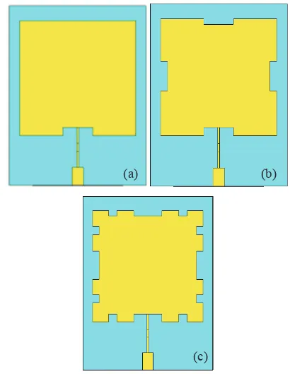
Sierpinski [14], Hilbert [15] and also Koch [16]. The Minkowski curve can be characterized by the iteration factor [17], shown in Figure 1. Zero iteration is represented by the normal patch without any scraped out of copper [18]. First iteration show that four rectangular or square shape of copper had been cut from the patch. Second iteration show another eight rectangular had been cut from the patch.
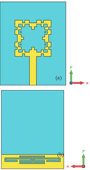
Figure 1. Schematic diagram of Minkowski Island patch antenna with split ring resonator at the ground plane, (a) plan view, (b) ground plane view
Minkowski Island is the improvement technique of the Minkowski fractal of embedding the Minkowski slot in the center of the antenna patch. There is also Minkowski Island
(a) (b)
(c)
that applied in the frequency selective surface [19], fractal monopole antenna [20], reflectarray antenna design [21] and microstrip patch antenna [22].
Split ring resonator (SRR) is an example of a left handed material (LHM) structure beside photonic band gap (PBG), electronic band gap (EBG) and artificial magnetic conductor (AMC). Double negative (DNG) metamaterial is posses negative values of dielectric permittivity and magnetic permeability. The basic structure of split ring resonators is edge couple split ring resonator (EC-SRR). The other researcher had been introduced many types of split ring resonator such as double H-shaped SRR (DH-RR) [23], quadruple P-spiral SRR (QPS-SRR) [24] and others. Different types of SRR structure also can be found in these technical papers [25-30].
This multiband Minkowski Island patch antenna with complementary SRR had been operating in three different bands of frequency that is 2.400 GHz and 5.200 GHz for WLAN while the 3.500 GHz for WiMAX application. The techniques used in these works are Minkowski Island fractal on the patch, partial ground and complementary split ring resonator of the ground plane.
II. ANTENNA DESIGN
The proposed antenna is designed on a FR-4 substrate with dielectric constant of 4.3 and a thickness of 1.6 mm. The thickness of the copper is 0.035 mm. Figure 2 shows the schematic diagram of the Minkowski Island patch antenna with complementary SRR at the ground plane.
Figure 2. Schematic diagram of Minkowski Island patch antenna with split ring resonator at the ground plane, (a) plan view, (b) ground plane view
This Minkowski Island patch antenna consists four main elements – patch, feed line, partial ground and complementary split ring resonator. The Minkowski patch part dimension is 16.48 mm width x 16.48 mm length, located at the top of the substrate. The feed line is located at the bottom of the patch antenna part with 13.15 mm in length. This patch antenna has the feeding structure of a 50 ohm microstrip line. The feed line is located between the rectangular parasitic patches element the at bottom part of the patch antenna. Table I shows the dimension of the modified Minkowski patch antenna.
TABLE I. DIMENSION OF THE MINKOWSKI ISLAND PATCH ANTENNA WITH SRR AT THE GROUND PLANE
Part Symbol Dimension (mm)
Substrate width Ws 30.00
Substrate length Ls 38.00
Patch width Wp 16.48
Patch length Lp 16.48
Feed width Wf 3.06
Feed length Lf 13.15
Ground width Wg 30.00
Ground length Lg 7.00
The complementary structure of split ring resonator had been attached at the ground plane of the FR-4substrate. It consists a combination of two main parts – straight line part and rectangular shaped split ring part. The location of this complimentary SRR is at the bottom of the partial ground plane. Figure 3 shows the complementary spiral split ring resonator structure on the ground plane. Table II shows the dimension of the complementary SRR structure. The width of this SRR structure is 13.00 mm width x 0.60 mm length. The gap of the split ring resonator structure is 0.50 mm.The straight line dimension is 12.00 mm width x 0.60 mm length.
Figure 3. Schematic diagram of complementary split ring resonator on the ground plane
(a)
TABLE II. DIMENSION OF SPLIT RING RESONATOR
Part Symbol Dimension (mm)
SRR width Ws 13.00
SRR length Ls 0.60
Straight line width WL 12.00
Straight line length LL 0.60
Gap between two SRR Wp 0.50
Figure 4 shows the stage of development of Minkowski Island patch antenna with different complementary split ring resonator. Design A is normal partial ground, located at the bottom of the FR-4 substrate. The dimension of this ground plane is 30.00 mm width x 7 mm length x 0.035 mm thick. In Design B, a pair of complementary SRR had been added into the partial ground while Design C consist of complementary SRR with two straight lines at the bottom at top of complementary SRR.
Figure 4. Minkowski Island patch antenna with different design on ground plane, (a) Design A - normal partial ground, (b) Design B - partial ground
with complementary SRR, (c) Design C - partial ground with extended complementary SRR
III. RESULT
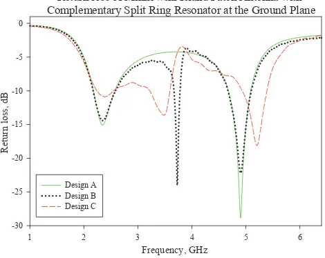
The parameters that are considered in this work are resonant frequency, return loss, bandwidth, gain and directivity of the antenna. Figure 4 and Table III represent the return loss from 1.000 GHz to 7.000 GHz frequency range of Minkowski Island patch antenna with complementary SRR structure (Design A, Design B and Design C).
The return loss of different three stages of Minkowski Island patch antenna with complementary SRR had been shown in Figure 5. The resonant frequency of Design A is at 2.400 GHz with – 14.380 dB of return loss and at 4.900 GHz with - 28.684 dB. The – 10.00 dB bandwidth of this design is 0.396 GHz at the frequency between 2.177 GHz and 2.573 GHz. The other bandwidth is 0.415 GHz at the frequency between 4.676 GHz and 5.091 GHz.
Return loss of Minkowski Island Patch Antenna with Complementary Split Ring Resonator at the Ground Plane
Frequency, GHz
1 2 3 4 5 6
R
et
ur
n
l
o
ss
,
dB
-30 -25 -20 -15 -10 -5 0
Design A Design B Design C
Figure 5. Minkowski Island patch antenna with complementary SRR on the ground (Design A, B and C)
The three resonant frequencies of Design B are 2.352 GHz, 3.728 GHz and 4.904 GHz with a respective return loss of - 14.418 dB, -23.863 dB, and – 22.234 dB. By the addition of the SRR, it creates a new resonant frequency at 3.728 GHz compared to the normal partial ground that have only two resonant frequencies.
The optimization of the wanted resonant frequencies had been done in Design C. The three resonant frequencies exist in this design are at 2.400 GHz, 3.500 GHz and 5.200 GHz with – 10.868 dB, - 13.554 dB and – 19.259 dB.
From the simulation, it shows that the second and the third resonant frequency (2.400 GHz and 5.200 GHz) had been optimized by resize (reduce or increase) the Minkowski patch antenna. The Minkowski Island shaped has the potential to reduce the size of the patch. The resonant frequency point of the middle resonant frequency (3.500 GHz) can be controlled by reducing the size of the SRR and also the number of the (a) (b)
SRR in the ground plane of the antenna.
TABLE III. RESONANT FREQUENCY,RETURN LOSS, AND BANDWIDTH OF DIFFERENT DESIGN OF MINKOWSKI ISLAND PATCH ANTENNA WITH SRR AT THE
GROUND PLANE
Design Resonant
frequency, fr
(GHz)
Return loss (dB)
Bandwidth (GHz),
f1-f2 (GHz)
Design
A
2.400 - 14.380 0.396,
2.177 - 2.573
4.900 - 28.684 0.415,
4.676 – 5.091
Design
B
2.352 - 14.418 0.417,
2.170 – 2.587
3.728 - 23.863 0.113,
3.669 – 3.782
4.904 - 22.234 0.432,
4.669 – 5.101
Design
C
2.400 - 10.868 0.309,
2.241 – 2.550
3.500 - 13.554 0.376,
3.218 – 3.594
5.200 - 18.112 0.458,
4.931 – 5.389
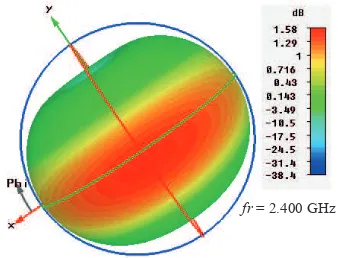
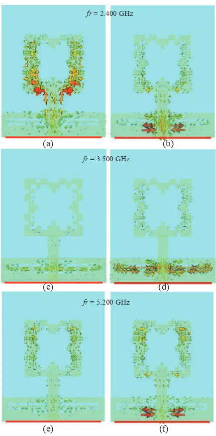
Figure 6 shown the 3D radiation pattern of Design C at resonant frequency, fr of 2.400 GHz. Figure 7 represents the 2D radiation pattern of the Minkowski Island patch antenna with complementary SRR (Design C). Figure 8 shows the surface current for Minkowski Island patch antenna with complementary SRR (Design A, Design B and Design C) at 2.400 GHz, 3.500 GHz and also at 5.2 GHz of frequency point.
Figure 6. Minkowski Island patch antenna with complementary SRR on the ground (Design A, B and C)
Figure 7. 2D radiation pattern at 900 for Design C (a) 2.4 GHz, (b) 3.5 GHz,
(c) 5.2 GHz
fr = 2.400 GHz
fr = 3.500 GHz
Figure 8. Surface current at various frequencies and degree for Design C, (a) 2.400 GHz at 900, (b) 2.400 GHz at 1800, (c) 3.500 GHz at 900, (d) 3.500 GHz
at 1800, (e) 5.200 GHz at 900, (d) 5.200 GHz at 1800
From the surface current schematic analysis, it shows that the Minkowski patch antenna are effected the at 2.400 GHz and also at 5.200 GHz of resonant frequency. The changes of the feedline also had been effect on these two frequencies. The split ring resonator structure and the partial ground technique are effected the 3.500 GHz of frequency.
Table IV shows the gain of the Minkowski Island patch antenna with SRR at the ground plane. It shows that the Design A had been achieved 1.575 dB at 2.400 GHz and 3.441 dB at 4.900 GHz. The addition of the split ring resonator in Design B had been created three bands of frequency with two positive gain result (1.551 dB at 2.352 GHz and 3.419 dB at 4.904 GHz) and a negative gain result at 3.720 GHz with
-0.782 dB. This problem had been cater while the optimization works in Design C. In this optimization design it shows that the 3.720 GHz of frequency had been shifted to the 3.500 GHz with positive gain of 1.410 dB. This antenna also achieved 1.286 dB at 2.400 GHz and 3.419 dB at 5.200 GHz.
TABLE IV. GAIN PERFORMANCE OF THE MINKOWSKI ISLAND PATCH ANTENNA WITH SRR AT THE GROUND PLANE
Design Resonant
frequency, fr
(GHz)
Gain (dB)
Design A 2.400 1.575
4.900 3.441
Design B 2.352 1.551
3.720 -0.782
4.904 3.419
Design C 2.400 1.286
3.500 1.410
5.200 3.419
The proposed antenna design can be potentially integrated with RF transmitter and RF receiver [31-32] to form a complete WLAN front-end system.
IV. CONCLUSION
From the simulation, it shows that the Minkowski Island patch antenna with complementary SRR in Design B and Design C had been successfully produced a multiband of resonant frequency. Design C had been improved the gain compared with Design B. The combination of the partial ground technique, split ring resonator technique and Minkowski Island technique had been making this antenna gain improved, miniaturized the patch size and develop the tri-band of frequency. Thus, the proposed antenna can be a suitable design for the tri-band operation for WLAN and WiMAX application.
REFERENCES
[1] B. H. Ahmad, M. M. Ariffin, H. Nornikman, N. M. S. Roslan, M. Z. A Abd Aziz, M. A. Atiqa, A. R. Ayuni, Y. W. Ming, “Parametric Study on the Compact G-Shaped Monopole Antenna for 2.4 GHz and 5.2 GHz Application,” International Journal of Engineering and Technology (IJET), vol. 5, issue 1, 2013, pp. 512 - 518
[2] H. M. R. Nurul, P. J. Soh, A. A. H. Azremi, N. A. Saidatul, S. R. Norra, M. I. Ibrahim, R. B. Ahmad, “A Dual Band Planar Monopole Antenna
(a) (b)
(c) (d)
(e) (f)
fr = 2.400 GHz
fr = 3.500 GHz
with Inverted-M Parasitic Plane, Asia-Pacific Conference on Applied Electromagnetics (APACE 2007),” 2007, pp. 1-4
[3] N.A Saidatul, A. A. H. Azremi, R. B. Ahmad, P. J. Soh, F. Malek, “A Development of Fractal PIFA (Planar Inverted F Antenna) With Bandwidth Enhancement for Mobile Phone Applications,” Loughborough Antennas & Propagation Conference, (LAPC 2009), 2009, pp. 113 - 116
[4] M. S. Zulkefli, F. Malek, M. F. Jamlos, M. H. Mat, S. H. Ronald, “Novel Small Peanut-shape Printed Antenna Design for WLAN-band Application,” 2011 Loughborough Antennas and Propagation Conference (LAPC 2011), 2011, pp. 1 - 4
[5] N. A. Rahman, P. J. Soh, A. A. M. Ezanuddin, H. Nornikman, “A Planar Elliptical UWB Antenna Applied on Different Substrates,” 4th International Conference on Electromagnetic Near Field Characterization and Imaging (ICONIC’09), 2009, pp. 169 - 172
[6] P. J. Soh, G. A. E. Vandenbosch, X. Chen, P. S. Kildal, S. L. Ooi, H. Aliakbarian, “Wearable Textile Antennas' Efficiency Characterization Using a Reverberation Chamber,” 2011 IEEE International Symposium on Antennas and Propagation (APSURSI), 2011, pp. 810 - 813
[7] F. H. Wee, F. Malek, “Design of Microstrip Patch Array Antenna Using Rectangular Barium Strontium Titanate (BST) Ceramic,” 2011 IEEE Symposium on Wireless Technology and Applications (ISWTA), 2011, pp. 40 - 43
[8] H. Nornikman, B. H. Ahmad, M. Z. A. Abd Aziz, A. R. Othman, “Rhombic Split Ring Resonator (R-SRR) Structure on Rectangular Patch Antenna Design,” International Journal of Electronics and Computer Science Engineering (IJECSE), vol. 2, no. 1, 2013, pp. 322-330
[9] A. A. H. Azremi, N. A. Saidatul, R. B. Ahmad, P. J. Soh, “A Parametric Study of Broadband Planar Inverted F Antenna (PIFA) for WLAN Application,” International Conference on Electronic Design (ICED 2008), 2008, pp. 1 - 6
[10] M. Z. A. Abd Aziz, Z. Daud, M. K. Suaidi, M. K. A. Rahim, “Analysis of Indoor MIMO Chanel Capacity Using Spatial Diversity Technique,” Journal of Telecommunication, Electronics and Computer Engineering (JTEC), vol. 2, 2010, pp. 55-60
[11] Y. Liu, X. Tang, Z. X. Zhang, X. L. Huang, “Novel Nested Split-Ring-Resonator (SRR) for Compact Filter Application,” Progress In Electromagnetics Research (PIER) , vol. 136, 2013, pp. 765-773
[12] E. C. Lee, P. J. Soh, N. B. M. Hashim, G. A. E. Vandenbosch, H. Mirza, I. Adam, S. L. Ooi, “Design of a flexible Minlowski-like pre fractal (MLPF) antenna with different ground planes for VHF LMR,”, 2011 International Workshop on Antenna Technology (iWAT 2011), 2011, pp. 298-301
[13] S. N. Shafie, I. Adam, P. J. Soh, “Design and Simulation of a Modified Minkowski Fractal Antenna for Tri-Band Application,” 2010 Fourth Asia International Conference on Mathematical/Analytical Modeling and Computer Simulation (AMS), 2010, pp. 567-570
[14] M. Waqas, Z. Ahmed, M. Bin Ihsan, “Multiband Sierpinski Fractal Antenna,” IEEE 13th International Multitopic Conference (INMIC 2009), 2009, pp. 1 - 6
[15] H. Oraizi, S. Hedayati, “Wideband Monopole Fractal Antenna with Hilbert Fractal Slot Patterned Ground Plane,” 2011 41st European Microwave Conference (EuMC), 2011, pp. 242 - 245
[16] A. Ismahayati, P. J. Soh, R. Hadibah, G. A. E. Vandenbosch, “Design and Analysis of a Multiband Koch Fractal Monopole Antenna,” 2011 IEEE International RF and Microwave Conference (RFM), 2011, pp. 58 - 62
[17] C. Mahatthanajatuphat, P. Akkaraekthalin, “A Double Square Loop Antenna with Modified Minkowski Fractal Geometry for Multiband Operation,” IEICE Transactions on Communications, Vol. E90-B, No. 9, 2007, pp. 2256–2262,
[18] E. C. Lee, P. J. Soh, N. B. M. Hashim, G. A. E. Vandenbosch, V. Volski, I. Adam, H. Mirza, M. Z. A. A. Aziz, “Design and Fabrication of a Flexible Minkowski Fractal Antenna for VHF Applications,” Antennas
and Propagation (EuCAP), Proceedings of the 5th European Conference on, 2011, pp. 521-524
[19] A. L. P. S. Campos, E. E. C. d. Olivera, “Design of Miniaturized Frequency Selective Surfaces Using Minkowski Island Fractal,” Journal of Microwaves, Optoelectronics and Electromagnetic Applications, vol. 9, no. 1, 2010
[20] Q. Luo, H. M. Salgado, J. R. Pereira, “Fractal Monopole Antenna Design Using Minkowski Island Geometry,” IEEE Antennas and Propagation Society International Symposium (APSURSI '09), 2009, pp. 1-4
[21] A. Wahid, M. K. A. Rahim, F. Zubir, “Analysis of Dual Layer Unit Cell with Minkowski Radiating Shape for Reflectarray Antenna on Different Substrate Properties,” 2010 IEEE Asia-Pacific Conference on Applied Electromagnetics (APACE 2010), 2010, pp. 1-5
[22] J. -C. C. Liu, C. -P. Kuei, C. -C. C. Chang, H.-H. Liu, “Dual-Mode Wide-Band and Dual-Band Resonators with Minkowski-Island-Based Fractal Patch for WLAN Systems,” Cross Strait Quad-Regional Radio Science and Wireless Technology Conference (CSQRWC), 2011, pp. 583 - 585
[23] J. Xiao, S. Ma, Y. Li, “A Novel H-Shaped Microstrip Resonator and Its Design to Filter using Defected Ground Structure,” 2005 Conference on High Density Microsystem Design and Packaging and Component Failure Analysis, 2005, pp. 1 -4
[24] F. Malek, H. Nornikman, M. S. Zulkefli, M. H. Mat, N. A. Mohd Affendi, L. Mohamed, N. Saudin, A. A. Ali, “Complimentary Structure of Quadruple P-Spiral Split Ring Resonator (QPS-SRR) on Modified Minkowski Patch Antenna Design,” 2012 IEEE Asia-Pacific Conference on Applied Electromagnetics (APACE 2012), 2012, pp. 142 – 147
[25] H. Nornikman, B. H. Ahmad, A. R. Othman, M. Z. A. Abdul Aziz, H. Imran, F. Malek, “Study and Simulation of a Edge Couple Spit Ring Resonator (EC-SRR) on Truncated Pyramidal Microwave Absorber,” Progress in Electromagnetics Research (PIER), vol. 127, 2012, pp. 319 - 334
[26] H. Nornikman, F. Malek, P. J. Soh, A. A. H. Azremi, “Design a Rice Husk Pyramidal Microwave Absorber with Split Ring Resonator,” The Asia-Pacific Symposium on Applied Electromagnetics and Mechanics 2010 (APSAEM 2010), 2010
[27] A. Kanso, R. Chantalat, M. Thevenot, U. Naeem, S. Bila, T. Monediere, “Multifeed EBG Dual Band Antenna to Feed a Reflector Antenna,” 2011 41st European Microwave Conference (EuMC), 2011, pp. 866 - 869
[28] D. N. Elsheakh, H. A. Elsadek, E. A. Abdallah, M. F. Iskander, H. Elhenawy, “Ultrawide Bandwidth Umbrella-Shaped Microstrip Monopole Antenna Using Spiral Artificial Magnetic Conductor (SAMC),” IEEE Antennas and Wireless Propagation Letters, vol. 8, 2009, pp. 1255 - 1258
[29] M. Nikfalazar, M. Sazegar, Y. Zheng, H. Maune, A. Mehmood, R. Jakoby, “Tunable Split Ring Resonators (SRR) Filter Based on Barium-Strontium-Titanate Thick Film,” 2012 The 7th German Microwave Conference (GeMiC), 2012, pp. 1 -4
[30] N. Ortiz, F. Falcone, M. Sorolla, “Radiation Efficiency Improvement of Dual Band Patch Antenna Based on a Complementary Rectangular Split Ring Resonator,” 5th European Conference on Antennas and Propagation (EUCAP), 2011, pp. 830-834
[31] N. A. Shairi, B. H. Ahmad, P. W. Wong, “Switchable Radial Stub Resonator for Isolation Improvement of SPDT Switch,” International Journal of Engineering and Technology (IJET), vol. 5, issue 1, 2013, pp. 460-467