ISSN 1818-4952
© IDOSI Publications, 2013
DOI: 10.5829/idosi.wasj.2013.21.1011
Corresponding Author: Nornikman Hassan, Center for Telecommunication Research and Innovation,
Faculty of Electronics and Computer Engineering, Universiti Teknikal Malaysia Melaka(UTeM), Hang Tuah Jaya, 76100, Durian Tunggal Melaka, Malaysia.
Tel: +6013-2994949, E-mail: [email protected].
Microstrip Patch Antenna with a Complementary Unit
of Rhombic Split Ring Resonator (R-SRR) Structure
Nornikman Hassan, Badrul Hisham Ahmad, Mohamad Zoinol Abidin Abd Aziz,
1 1 1
Zahriladha Zakaria, Mohd Azlishah Othman, Abdul Rani Othman,
1 1 1
Kamaruzaman Jusoff and Zanariah Jano
2 3
Center for Telecommunication Research and Innovation (CeTRI),
1
Faculty of Electronics and Computer Engineering, Universiti Teknikal Malaysia Melaka (UteM), Hang Tuah Jaya, 76100, Durian Tunggal, Melaka, Malaysia
Department of Forest Production, Faculty of Forestry,
2
Universiti Putra Malaysia, 43400 UPM Serdang, Selangor, Malaysia
Centre for Languages and Human Development, Universiti Teknikal Malaysia Melaka (UteM),
3
Hang Tuah Jaya, 76100, Durian Tunggal, Melaka, Malaysia
Abstract: Hitherto, split ring resonator is becoming a popular structure in antenna design. The objective of this paper is to determine the effect of the rhombic complimentary split ring resonator structure (R-SRR) on microstrip patch antenna design. The basic microstrip patch antenna design is simulated in CST Microwave Studio simulation software. The findings show that the resonant frequency of this antenna is 2.40 GHz for Wireless Local Area Network (WLAN) application. The R-SRR structure has increased the gain and efficiency of microstrip patch antenna. Therefore, the users will get a better coverage of WLAN signal. The different number of split rings may offer attractive results in the future.
Key words: Split ring resonator % Microstrip antenna % Wireless Local Area Network
INTRODUCTION Metamaterial is the artificial substrate which is In a telecommunication research area, patch antenna categorized as the structure which has simultaneously is popular because it is easy to fabricate. Wireless Local negative permeability and permittivity values. Many Area Network or WLAN is commonly used in the current metamaterial structures have been proposed [7-10]. technological applications and devices such as The structures include artificial magnetic conductor notebooks, laptops and mobile phones. An antenna is (AMC) [7], electromagnetic band gap (EBG) [8], split the device used for transmitting and receiving ring resonator (SRR) [9] and photonic band gap (PBG) electromagnetic waves. Many types of patch antenna [10].
exist such as meander line [1], circular polarize [2], These metamaterial structures are used in several Minkowski [3], oval shaped [4]. Many researchers have applications such as microwave absorber [11], improved the parameter results to produce better antennas [12], frequency selective surfaces (FSS) performance of the patch antenna design. The parameters [13] and metamaterial filters [14]. Metamaterial structure which need improvements include return loss, gain, such as split ring resonators (SRRs) design is used to directivity and bandwidth. These improvements cover produce the negative dielectric constant (permittivity) various shapes of antennas, additional special structures, and negative permeability. This structure has been attachment of RF components or integrated circuits into been initially discovered by Veselago [5]. Smith et al.
Their design depends on Pendry split ring resonator-based artificial negative magnetics permeability media.
There are many types of split ring resonator design such as edge coupled SRR (EC-SRR) [15], broadside-couple SRR (BC-SRR) [16], nonbianistropic SRR (NB-SRR) [17] and other SRR structures. This paper determines the effect of the rhombic complimentary split ring resonator structure (R-SRR) on microstrip patch antenna design.
MATERIALS AND METHODS
Rhombic SRR Design: There are many new shapes proposed in the literature. The popular shape is circular and square shape while the other shapes are rectangular, triangular, hexagonal, rhombic (diamond), oval, H-shaped, V-shaped and others. Different shape gives different result of the return loss and gain. Figure 1 shows the single unit of rhombic complimentary split ring resonator design. This structure is printed on the Roger RT/Duroid 5880 substrate with dielectric constant, gr = 2.2. The thickness of the copper is 0.035 mm. Table 1 shows the dimension of the single unit of rhombic complimentary SRR. The size of the rhombic complimentary SRR structure is 3.93 mm width x 3.93 mm length. The dimension of the ring gap, Ws is 0.98 mm while the thickness of the ring, Tr = 0.35 mm.
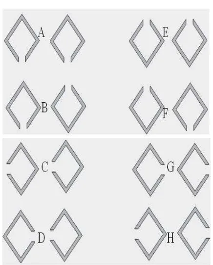
In this work, eight different variation patterns have been simulated to compare the return loss and gain performance between the normal patch and rhombic SRR patch antenna. The distance of the two rings is 10 mm while the ring width is 3.93 mm and the ring gap is 0.98 mm. These dimensions are similar to the single unit of rhombic SRR structure. Figure 2 shows the variation pattern of a single unit of the rhombic SRR.
Antenna with Rhombic SRR Design: This design is simulated in CST Microwave Studio simulation software. This structure is printed on the Roger RT/Duroid 5880 substrate with dielectric constant gr =2.2. The dimension
of the board is 60 mm width x 80 mm length. The ground plane is printed in the back side of the substrate with the dimension of 60 mm width x 80 mm length. A 50 S
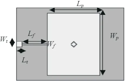
waveguide port is used to feed power into the radiator. Figure 3 shows the schematic diagram of the basic microstrip patch antenna design while Table 2 shows the dimension of the microstrip patch antenna design.
Figure 4 shows the location of the rhombic split ring resonator at the center of the patch antenna and is paralleled with the feed line of the patch antenna.
Table 1: The dimension of the single unit of rhombic SRR design
Part Symbol Dimension (mm)
Ring width Wr 3.93
Ring gap Ws 0.98
Thickness of ring Tr 0.35
Table 2: Dimension of the normal and optimization dimension of patch antenna
Fig. 1: Single rhombic complimentary split ring resonator structure on CST Microwave Studio. The green line is the RT/Duroid 5880 substrates
Fig. 3: Single rhombic complimentary split ring resonator SRR indicates 6.372 dB, an improvement of 0.038 dB. The structure on CST Microwave Studio SRR structure affects the targeting frequency of 2.40 GHz
Fig. 4: Microstrip patch antenna with rhombic SRR the-10 dB bandwidth. All design acquire the same
structure resonant frequency that is 2.396 GHz. It only affects the
The dimension of this SRR antenna is similar to the normal return loss is shown by 30 mm distance with - 31.795 dB. patch antenna design. Table 3 shows the comparison of The highest gain is 15 mm distance with 6.372 dB. Table dimension between normal patch antennas and patch 4 shows the comparison return loss, bandwidth and gain antenna with rhombic SRR structure. From the theory, we results of the different distances between the two SRR know that the rhombic SRR will increase the gain structures.
performance of the antenna. It also shifts the targeting Figure 9 and Table 5 show the effect of the rhombic frequency of the return loss result to other range of SRR size on the return loss of the patch antenna. frequency. Hence, the antenna dimension (especially the Four different sizes used are 2.45 mm, 3.68 mm, 4.91 mm length of the feed line) must be optimized to locate the and 6.13 mm. The larger rhombic SRR size gives the targeting frequency and targeting 50 S of impedance highest return loss performance result with - 35.639 dB
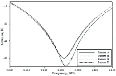
matching. Table 2 represents the optimization dimension but does not give the highest gain. An antenna with of the patch antenna design with the rhombic SRR the 2.45 mm of rhombic SRR size with 6.495 dB shows structure compared to the normal patch antenna design. the highest gain. The rhombic SRR size affects the The incorporation of the rhombic SRR structure can location of the resonant frequency. For example, the minimize the microstrip patch antenna design. resonant frequency of 2.45 mm rhombic SRR is 2.398 RESULTS AND DISCUSSION Different variation pattern also affects the The parameters which are analyzed include the effect show that Pattern A and B give the best gain results with of the rhombic SRR structure on patch antenna design, 6.372 dB while Pattern C and Pattern D score poorly with different distance between two rhombic SRR structures, only 6.310 dB. All SRR patterns show the same resonant different size of rhombic SRR structures and different frequency and bandwidth that is 2.396 GHz and 51 MHz. variation patterns of rhombic SRR structures. The return Table 6 shows that the best return loss is shown by loss of normal patch antenna (without SRR structure) is Pattern D with - 32.200 dB compared to Pattern A with shown in Figure 5. The resonant frequency of this design only - 30.026 dB.
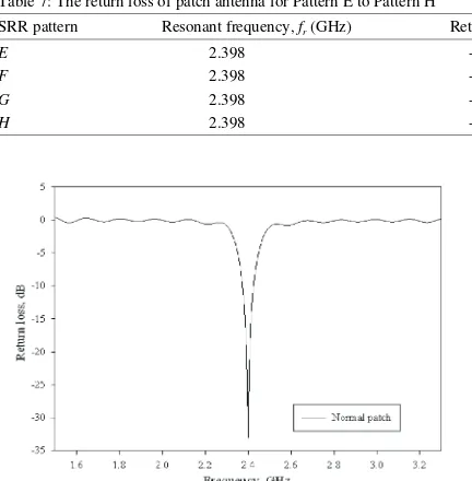
is at 2.40 GHz with - 32.846 dB of return loss. The - 10 dB bandwidth of this design is at the frequency between 2.374 GHz and 2.425 GHz.
Figure 6 and Table 3 represent the comparison of return loss performance between the normal patch antenna and rhombic SRR patch antenna. The gain of the patch antenna is increased by incorporating the single unit of rhombic SRR structure.
The new gain of the patch antenna with the rhombic
for this design. The SRR structure is shifted by 22 MHz of the frequency in the 2.422 GHz. After the antenna dimension optimization (redesign) is performed, the frequency is located at the 2.40 GHz. With the optimization process for the patch antenna, the gain of the antenna is increased from 6.372 dB to 6.402 dB. Figure 7 shows a comparison of the 3D return loss of the antenna design.
Figure 8 shows the return loss of the patch antenna with the different distance between two SRR structures. The different dimension between the two SRR does not give any effect to the frequency location and
return loss and gain performance result. Hence, the best
GHz.
Table 3: Dimension of the normal patch and the optimization dimension of patch antenna
Antenna design Resonant frequency, fr (GHz) Return loss (dB) Bandwidth (MHz), f1-f2 (GHz) Gain (dB)
Normal patch 2.400 - 32.846 51 (2.374 - 2.425) 6.334
Rhombic SRR 2.422 - 24.029 53 (2.396 - 2.449) 6.372
Rhombic SRR (redesign) 2.400 - 26.883 51 (2.374 - 2.425) 6.402
Table 4: Return loss of patch antenna with different distance between two SRR structures
Distance between two SRR structure Resonant frequency, fr (GHz) Return loss (dB) Bandwidth (MHz), f1-f2 (GHz) Gain (dB)
10 mm 2.396 - 30.595 52 (2.370 - 2.422) 6.323
15 mm 2.396 - 30.026 52 (2.370 - 2.422) 6.372
20 mm 2.396 - 31.736 52 (2.370 - 2.422) 6.366
30 mm 2.396 - 31.795 52 (2.370 - 2.422) 6.367
Table 5: The return loss of patch antenna with different size of SRR structure
SRR size (mm) Resonant frequency, fr (GHz) Return loss (dB) Bandwidth (MHz), f1-f2 (GHz) Gain (dB)
2.45 2.398 - 29.167 50 (2.374 - 2.424) 6.495
3.68 2.398 - 33.895 52 (2.373 - 2.425) 6.321
4.91 2.396 - 30.026 52 (2.370 - 2.422) 6.372
6.13 2.390 - 35.639 51 (2.365 - 2.416) 6.334
Table 6: The return loss of patch antenna for Pattern A to Pattern D
SRR pattern Resonant frequency, fr (GHz) Return loss (dB) Bandwidth (MHz), f1-f2 (GHz) Gain (dB)
A 2.396 - 30.026 52 (2.370 - 2.422) 6.372
B 2.396 - 31.902 52 (2.371 - 2.423) 6.310
C 2.396 - 30.091 52 (2.370 - 2.422) 6.372
D 2.396 - 32.200 52 (2.371 - 2.423) 6.310
Table 7: The return loss of patch antenna for Pattern E to Pattern H
SRR pattern Resonant frequency, fr (GHz) Return loss (dB) Bandwidth (MHz), f1-f2 (GHz) Gain (dB)
E 2.398 - 31.418 51 (2.373 - 2.424) 6.381
F 2.398 - 32.613 51 (2.374 - 2.425) 6.323
G 2.398 - 31.378 51 (2.373 - 2.424) 6.371
H 2.398 - 32.417 51 (2.373 - 2.424) 6.379
Fig. 5: Return loss of single rhombic R-SRR antenna Fig. 6: Return loss of Single R-SRR antenna
Figure 10 and Table 7 show the effect of the different These entire four patterns show the same resonant variation patterns of rhombic SRR on the return loss of frequency result that is 2.398 GHz but is located the absorber. Four patterns analyzed are Pattern E, Pattern differently for Pattern A, Pattern B, Pattern C and Pattern
F, Pattern G and Pattern H. The higher gain performance D. Pattern F scores the best return loss performance is shown by Pattern E with 6.381 dB while the worst gain with - 32.613 dB followed by Pattern E and Pattern H
Fig. 7: The 3D return loss of the antenna: (a) Normal patch antenna, (b) Rhombic SRR antenna, (c) Optimization design of rhombic SRR antenna
Fig. 8: The return loss of patch antenna with different Fig. 10: The return loss of patch antenna for Pattern A to distance between two SRR structures Pattern D
Fig. 9: The return loss of patch antenna with different Studio simulation software, the rhombic split ring size of SRR structure resonator (R-SRR) has improved the gain of the
Fig. 10: The return loss of patch antenna for Pattern E to WLAN signal. Future research suggested that the
Patern H microstrip patch antenna can be improved by adding the
shown by Pattern G with only - 31.378 dB. All variation patterns (Pattern A to Pattern H) show the same - 10 dB bandwidth to 51 MHz of frequency range. Overall, different variation patterns do not affect the - 10 dB bandwidth but only shift the frequency into the new resonant point.
CONCLUSION
From the simulation work in CST Microwave
N-number rings and the array split ring resonator 9. Nornikman, H., B.H. Ahmad, M.Z.A. Abdul Aziz, structures or defining the new shape design of the split F. Malek, H. Imran and A.R. Othman, 2012. Study and ring resonator structure. Simulation of an Edge Couple Split Ring Resonator REFERENCES Absorber. Progress In Electromagnetics Research, 1. Misman, D., M.Z.A. Abd Aziz, M.N. Husain and 10. Patel, S.S. and Y.P. Kosta, 2011. Multiband PBG P.J. Soh, 2009. Design of Planar Meander Line Suspended Patch Antenna, 2011 3 International Antenna, 3 European Conference on Antennas andrd Conference on Electronics Computer Technology Propagation (EuCAP), Berlin, Gemany, pp: 2420-2424. (ICECT), Kanyakumari, India, pp: 5-9.
2. Aziz, M.Z.A., N.A.D.A. Mufit, M.K. Suadi, A. Salleh 11. Nornikman, H., F. Malek, P.J. Soh and A.A.H. Azremi, and M.K.A. Rahim. 2012. Study on Microstrip 2010. Design a Rice Husk Pyramidal Microwave X-Linear Polarized and X-Circular Polarized Antenna, Absorber with Split Ring Resonator, The Asia-Pacific 2012 6th European Conference on Antennas and Symposium on Applied Electromagnetics and Propagation (EuCAP 2012), Prague, Czech Republic, Mechanics 2010 (APSAEM 2010), Kuala Lumpur,
pp: 907-911. Malaysia.
3. Lee, E.C., P.J. Soh, N.B.M. Hashim, G.A.E. 12. Ezanuddin, A.A.M., F. Malek and P.J. Soh, 2010. Vandenbosch, V. Volski, I. Adam, H. Mirza and M. Investigation of Complementary Split Ring Z.A.A. Aziz, 2011. Design and Fabrication of a Resonators with Dielectric Ring. 2010 Loughborough Flexible Minkowski Fractal Antenna for VHF Antennas and Propagation Conference (LAPC), Applications, Proceedings of the 5th European Loughborough, United Kingdom, pp: 297-300. Conference on Antennas and Propagation (EuCAP), 13. Kern, D.J., D.H. Werner, A. Monorchio, L. Lanuzza Rome, Italy, pp: 521-524. and M.J. Wilhelm, 2005. The Design Synthesis of 4. Zulkefli, M.S. and F. Malek, 2011. Novel Dual-Oval Multiband Artificial magnetic Conductors using High Shape Antenna with Bandstop Characteristic for Impedance Frequency Selective Surfaces. IEEE UWB Application, 2011 IEEE Symposium on Transactions on Antennas and Propagation, Wireless Technology and Applications (ISWTA), 53(1): 8-17.
Langkawi, Malaysia, pp: 137-140. 14. Das, S., A. Kundu, S. Maity, S. Dhar and B. Gupta, 5. Veselago, V.G., 1968. The Electrodynamics of 2011. Novel Compact CPW Filter for MICs Using Substances with Simultaneously Negative Values of Metamaterial Structures. 2011 11th Mediterranean permittivity and permeability. Soviet Physics Microwave Symposium (MMS), Hammamet, Tunisia,
USPEKI, 10(4): 509-514. pp: 286-289.
6. Smith, D.R., W.J. Padilla, D.C. Vier, 15. Majid, H.A., M. Rahim and T. Masri, 2008. S.C. Nemat-Nasser and S. Schultz, 2000. Left Handed Metamaterial Design For Microstrip Composite Medium with Simultaneously Negative Antenna Application. IEEE International RF and Permeability and Permittivity. Physical Review Microwave Conference (RFM 2008), Kuala Lumpur,
Letters, 84(1): 4184-4187. Malaysia, pp: 218-221.
7. Elsheakh, D.N., H.A. Elsadek, E.A. Abdallah, 16. Ekmekci, E. and G. Turhan-Sayan, 2011. M.F. Iskander and H. Elhenawy, 2009. Ultrawide Metamaterial Sensor Applications Based on Bandwidth Umbrella-Shaped Microstrip Monopole Broadside-couple SRR and V-Shaped Resonator Antenna Using Spiral Artificial Magnetic Conductor Structures. 2011 IEEE International Symposium on (SAMC). IEEE Antennas and Wireless Propagation Antennas and Propagation (APSURI), Washington,
Letters, 8(1): 1255-1258. USA, pp: 1170-1172.
8. Al-Hasan, M.J., T.A. Denidni and A. Sebak, 2011. A 17. Marques, R., R. Medinaand and E. I. Raffi, 2002. New UC-EBG Based-dielectric Resonator Antenna Role of Bi-anistropy in Negative Permeability and for Millimeter-wave Applications. 2011 IEEE Left-handed Metamaterials. Physical Review B, 65(1), International Symposium on Antennas and pp: 1-6.
Propagation (APSURSI), Washington, USA, pp: 1274-1276.
(EC-SRR) on Truncated Pyramidal Microwave 127(1): 319-334.