Rhombic Split Ring Resonator (R-SRR)
Structure on Rectangular Patch Antenna Design
H. Nornikman
1, B. H. Ahmad
1, M. Z. A. Abd Aziz
1, A. R. Othman
11
Center for Telecommunication Research and Innovation (CeTRI) Faculty of Electronic and Computer Engineering Universiti Teknikal Malaysia Melaka, Melaka, Malaysia
[email protected], [email protected], [email protected], [email protected]
Abstract- This work focusing on the effect of the complementary rhombic split ring resonator (R-SRR) structure of gain, return loss and the radiation pattern the rectangular patch antenna design. The basic rectangular patch antenna design had been simulated in CST Microwave Studio simulation software. Then, the single unit of the R-SRR had been added into the patch antenna design. The targeting frequency of this antenna is 2.40 GHz for Wireless Local Area Network (WLAN) application. Compared with the conventional microstrip patch antenna with the same aperture size, the performance gain of the patch antennas is improved obviously and suitable for targeting frequency of 2.40 GHz. The parametric studies done this work work are the different variation pattern of SRR, different distance between two R-SRR structure and different size of R-R-SRR.
Keywords – split ring resonator, metamaterial, microstrip patch antenna
I.INTRODUCTION
Microstrip patch is the common antenna shape that can be applied in various applications such as Wireless Local Area Network (WLAN) [1], Worldwide Interoperability for Microwave Access (WiMAX), Radio Frequency Identification (RFID) and others. Metamaterial is the artificial material that did not exist in the real nature and only founded by design a special structure of the normal substrate. Metamaterial have an important role to improve the performance in many devices and application such as filter [2], antenna [3], frequency selective surface [4], microwave absorber [5-6] and others. Metamaterial such as a split ring resonator (SRR) structure had been categorized as the structure or design that has simultaneously negative permeability and permittivity value.
Victor Veselago in 1968 had been predicted that the propagation of an electromagnetic wave is effected from both dielectric constant, εr and magnetic permeability, µ of the material [7]. This properties had been predicted by applying the basic concept of Snell’s law, Cherenkov radiation law and Doppler Effect. Pendry had been introduced the split ring resonator structure with a combination of the concentric ring metal wires. His structure had been designed based on cylinder coil effect by the wounded metallic sheet [8]. Then, Smith and his group had been firstly fabricated the first artificial metamaterial [9] based on Pendry’s SRR work.
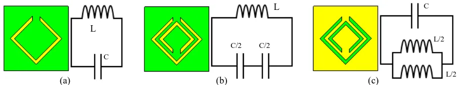
Figure 1: Rhombic SRR structure with its equivalent circuit. (a) Single R-SRR, (b) Double R-SRR, (c) Complemetary double R-SRR.
(a) (b) (c)
C L
C/2 C/2
C
L/2
This SRR unit cell can be transformed by an equivalent circuit using capacitor and inductor element [10]. In this case the gap between the rings can be shown by a capacitor while the long strip can be represented by the inductor. Figure 1 shows the double rings of SRR and complementary rings of SRR with its equivalent circuit. Basically, the SRR is composed of two concentric circular or square stripe metallic rings on the substrates. The other shapes available are rhombic, spiral, Minkowski, open shape, H-shape, and omega shape. The basic parameter that can be investigated in the split ring resonator are ring thickness, inner diameter, the gap of the ring, and the gap between two rings. Table 1 shows the previous work on the SRR structure on the various antennas. The parameters that consider in this table are SRR size, resonant frequency, return loss and gain.
Table-1 The dimension of the single unit of rhombic SRR design
Researcher, year
SRR structure type Application SRR Size (mm)
Edge-coupled SRR Slot dipole antenna
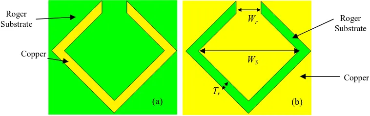
Figure 2 shows the schematic diagram of the single rhombic SRR. This R-SRR structure printed on the Roger RT/Duroid 5880 substrate with dielectric constant, εr =2.2 and copper thickness of 0.035 mm. Table 1 shows the
dimension of the single unit of rhombic complimentary SRR. The size of the rhombic complimentary SRR structure is 3.93 mm width x 3.93 mm length. The dimension of the ring gap, Ws is 0.98 mm while the thickness of the ring
stripe, Tr = 0.35 mm. The green color is the RT/Duroid 5880 substrates while the yellow color is copper [17].
Figure 2: (a) Single rhombic split ring resonator structure. (b) Single rhombic complimentary split ring resonator structure.
Part Symbol Dimension (mm)
Ring width Wr 3.93
Ring gap Ws 0.98
Thickness of ring stripe Tr 0.35
Gap between two rings Rr 0.86
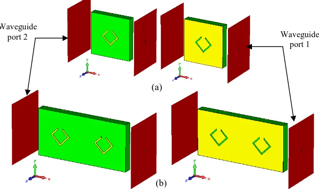
Figure 3(a) shows the single unit of rhombic split ring resonator in CST Microwave Studio simulation setup while Figure 3(b) shows the double units complementary structure of the rhombic split ring resonator. The red square zone is the waveguide port 1 and waveguide port 2 that refer to the reflection coefficient, S11 and transmission
coefficient, S21.
Figure 3: (a) Single unit rhombic split ring resonator structure (b) Double units rhombic split ring resonator structure
Figure 4 shows the variation pattern of a double units of rhombic SRR. In this work, eight different of R-SRR variation pattern had been simulated to compare the return loss and gain performance between the normal patch antenna and rhombic SRR patch antenna. The distances between two rings are 10 mm while the ring width is 3.93 mm and ring gap is 0.98 mm came with the single unit of rhombic SRR structure.
Figure 4: The variation pattern of a double units of rhombic SRR – Pattern A to Pattern H
II.ANTENNA DESIGN
Figure 5(a) shows the schematic diagram of the normal microstrip patch antenna design in CST Microwave Studio simulation. This structure printed on the Roger RT/Duroid 5880 substrate with dimension of 60 mm width x
A B
C D
E F
G H
(a)
(b) Waveguide
port 2 Waveguide
80 mm length. The ground plane is printed on the back side of the substrate with dimension of 60 mm width x 80 mm length also. A 50 Ω waveguide port is used to feed power into the radiator. Figure 5(b) shows the location of the rhombic split ring resonator at the center of the patch antenna. This structure located parallel with the feed line of the patch antenna. The dimension of this SRR A-type antenna is same like normal patch antenna design, but it will shift the resonant frequency at the high point. After that, an optimization dimension had been done to locate back the resonant frequency to 2.40 GHz.
Figure 5: (a) Normal rectangular patch antenna (b) Rectangular patch antenna with single R-SRR, (c) Rectangular patch antenna with double R-SRR
Figure 5(c) shows the location of the rhombic split ring resonator at the center of the patch antenna and parallel with the feed line of the patch antenna. The dimension of this SRR antenna is same like normal patch antenna design. Table 3 shows the comparison of dimension between normal patch antennas with patch antenna with rhombic SRR structure. From the theory, the rhombic SRR will increase the performance gain of the antenna. It also shifts the targeting frequency of the return loss result to other range of frequency. So, we must optimize the antenna dimension (especially the length of the feed line) to locate back the targeting frequency and targeting 50 Ω of impedance matching. Table 3 represents the dimension of the normal microstrip patch antenna and patch antenna with R-SRR. The optimization dimension of the patch antenna design with rhombic SRR structure also had been shown by B-type patch antenna.
Table-3 Dimension of the microstrip patch antenna
Part Symbol Dimension (mm)
Normal patch
Patch with rhombic SRR A-type
Patch with rhombic SRR B-type (optimization)
Patch length Wp 51.5 51.5 51.5
Patch width Lp 38.7 38.7 39.15
Feed line A width Wt 1 1 1
Feed line A length Lt 19 19 19
Feed line B width Wf 4.72 4.72 4.75
Feed line B length Lf 7.7 7.7 4
III.EXPERIMENT AND RESULT
This section discuss on the resonant frequency, return loss, gain, and bandwidth result of the microstrip patch antenna with rhombic complimentary split ring resonator performance result. The parameters that are considered in this work are the effect of the rhombic SRR structure on patch antenna design, different distance between two rhombic SRR structures, different size of rhombic SRR structures, and different variation patterns of rhombic SRR
Roger Substrate
Rectangular Patch
Feed line B Feed line A
Wp
Wf Lf
Wt
(a) (b)
Lp
Lt
(c)
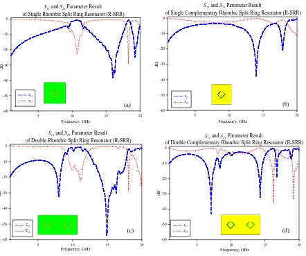
structures.. The resonant frequency of this design is at 2.40 GHz with - 32.846 dB of return loss. The - 10 dB bandwidth of this design is at the frequency between 2.374 GHz and 2.425 GHz. Figure 6 shows on the transmission coefficient, S11 and reflection coefficient S21 result for single rhombic, single complementary rhombic, double
rhombic and double complementary rhombic.
S11 and S21 Parameter Result
of Single Rhombic Split Ring Resonator (R-SRR)
Frequency, GHz
of Single Complementary Rhombic Split Ring Resonator (R-SRR)
Frequency, GHz
of Double Rhombic Split Ring Resonator (R-SRR)
Frequency, GHz
of Double Complementary Rhombic Split Ring Resonator (R-SRR)
Frequency, GHz
Figure 6: S11 and S21 performance of R-SRR using two port measurement in CST simulation software, (a) single R-SRR, (b) Complimentary single
R-SRR, (c) Double R-SRR, (d) Complimentary double R-SRR
Figure 7 and Table 4 represent the comparison of return loss performance between the normal patch antenna and rhombic SRR patch antenna. The gain of the patch antenna had been increased by incorporating with the single unit of rhombic SRR structure.
(a) (b)
Return Loss of Normal Patch Antenna and Patch Antenna with Rhombic SRR Structure
Frequency, GHz
2.2 2.3 2.4 2.5 2.6
R
et
u
rn
L
o
ss
,
d
B
-35 -30 -25 -20 -15 -10 -5 0 5
Normal patch Patch with R-SRR Patch with R-SRR (redesign)
Figure 7: Single rhombic complimentary split ring resonator structure of CST Microwave StudioSingle rhombic complimentary split ring resonator structure of CST Microwave Studio
The new gain of the patch antenna with rhombic SRR is 6.372 dB, an improvement of 0.038 dB. The SRR structure effected the targeting frequency of 2.40 GHz for this design. The SRR structure had been shifted 22 MHz of the frequency to the 2.422 GHz. After antenna dimension optimization (redesign) done, the frequency had been located back to the 2.40 GHz. With optimization process for patch antenna, the gain of the antenna had been increased from 6.372 dB to 6.402 dB. Figure 8 shows comparison the 3D return loss of the antenna design.
Table-4 Dimension of the normal patch and the optimization dimension of microstrip patch antenna
Antenna design Resonant frequency,
fr (GHz)
Return loss (dB) Bandwidth (MHz),
f1-f2 (GHz)
Gain (dB)
Normal patch 2.400 - 32.846 51 (2.374 – 2.425) 6.334
Rhombic SRR 2.422 - 24.029 53 (2.396 – 2.449) 6.372 Rhombic SRR (redesign) 2.400 - 26.883 51 (2.374 - 2.425) 6.402
Figure 8: The 3D return loss of the antenna: (a) Normal patch antenna, (b) Rhombic SRR antenna, (c) Optimization design of rhombic SRR antenna
Return Loss of Patch Antenna with Different Distance Between Two SRR Structures
Frequency, GHz
2.380 2.385 2.390 2.395 2.400 2.405 2.410
R with Different Size of SRR
Frequency, GHz
Figure 9: (a) The return loss of patch antenna with different distance between two SRR structures. (b) The return loss of patch antenna with different size of SRR structure
Table-5 Return loss of patch antenna with different distance between two SRR structures, Rr
Distance
Table-6 The return loss of patch antenna with different size of SRR structure
SRR size
Figure 9(a) and Table 5 shows the return loss of patch antenna with different distance between two SRR structures. From the graph it shows that the different dimension between two SRR did not give any effect to the frequency location and the -10 dB bandwidth. All design had been achieved the same resonant frequency that is 2.396 GHz. It's only effect the return loss and gain performance result. It shows that the best return loss is shown by 30 mm distance with - 31.795 dB. The highest gain had been achieved by 15 mm distance with 6.372 dB. Table 4 shows the comparison return loss, bandwidth and gain result between different distances between two SRR structures. Figure 9(b) and Table 6 shows the effect of the rhombic SRR size on the return loss of the patch antenna. Four different sizes had been considered in this section that is 2.45 mm, 3.68 mm, 4.91 mm, and 6.13 mm. The larger rhombic SRR size gives the highest return loss performance result with – 35.639 dB but not give the highest gain. The highest gain had been achieved by antenna with 2.45 mm of rhombic SRR size with 6.495 dB. The rhombic SRR size had been effect the location of the resonant frequency. For example the resonant frequency of 2.45 mm rhombic SRR is 2.398 GHz.
Return Loss of Patch Antenna with Different Variation Pattern (I)
Frequency, GHz
2.380 2.385 2.390 2.395 2.400 2.405 2.410
R with Different Variation Pattern (II)
Frequency, GHz
2.385 2.390 2.395 2.400 2.405 2.410
R
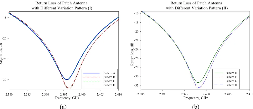
Figure 10: The return loss of patch antenna with different variation pattern (a) Pattern A, B, C and D. (b) Pattern E, F, G and H
Different variation pattern also effects the performance of the patch antenna. From the Figure 10(a) and Table 7, it shows that pattern A and pattern B give the best gain result with 6.372 dB while the worst had been shown by pattern C and pattern D with only 6.310 dB. All SRR pattern shows the same resonant frequency and bandwidth that is 2.396 GHz and 51 MHz. From the table, it shows that the best return loss is shown by pattern D with - 32.200 dB compare with Pattern A with only – 30.026 dB.Another four patterns are considered that were pattern E, pattern F, pattern G, and pattern H shown in Figure 10(b). The higher gain performance had been shown by pattern E with 6.381 dB while the worst gain performance had been shown by pattern F with only 6.323 dB.
Table-7 The return loss of patch antenna with different variation pattern (Pattern A to Pattern H)
SRR pattern Resonant frequency, fr (GHz)
Return loss (dB) Bandwidth (MHz),
f1-f2 (GHz)
These entire four patterns show the same resonant frequency result that is in 2.398 GHz but it located different with the pattern A, pattern B, pattern C, and pattern D. Pattern F achieved the best return loss performance with - 32.613 dB followed by pattern E and pattern H with – 32.418 dB and -32.417 dB. The worst return loss had been shown by pattern G with only – 31.378 dB. All variation patterns (Pattern A to pattern H) show the same - 10 dB bandwidth with 51 MHz of frequency range. So, for a conclusion different variation pattern did not effect the - 10 dB bandwidth but only shifted frequency into the new resonant point.
The proposed antenna design can be integrated with RF transmitter [18] and R receiver [19] to form a complete WLAN front-end system.
IV.CONCLUSION
From the observation, the radiation pattern of the antenna with rhombic split ring resonator (R-SRR) structure has an improved gain compared to the gain of the normal rectangular antenna without split ring resonator structure. An improvement of the gain by 0.068 dB from 6.634 dB to 6.402 dB. The addition of a pair of R-SRR on the center part of the antenna can shift the resonant frequency into the lower point. So, this will effect the size of the rectangular patch antenna into smaller size. From the simulation also, it shows that the antenna with SRR pattern E shows the highest gain compare other variation pattern. The changes dimension in parametric study can effect the performance of the return loss but not give the higher impact. For the future work, the combination of other technique with split ring resonator can be applied to improve the gain and return loss of the microstrip patch antenna.
V.REFERENCE
[1] V. Sharma, D. Arya, Dual Band Microstrip Patch Antenna Using DUal Feed for Wirless Applications, International Journal of Electronics and Computer Science Engineering, vol 1, no. 1, pp. 230-238
[2] M. Gil, J. Bonache, F. Martin, Metamaterial Filters: A Review, Metamaterial, vol. 2, pp. 186-197, 2008
[3] H. A. Majid, M. K. A. Rahim, T. Masri, Left Handed Metamaterial Design For Microstrip Antenna Application, 2008 IEEE International RF and Microwave Conference, pp. 218-221, 2008
[4] M. N. M. Kehn, E. R. Iglesias, Moment Method Analysis of Dispersion in SRR-Type FSS Loaded Rectangular Waveguides using Spectral Domain Green’s Functions and RWG Basis Functions Description of the Structure, 2007 IEEE Antennas and Propagation Society International Symposium, pp. 165-168, 2007
[5] H. Nornikman, B. H. Ahmad, M. Z. A. Abd. Aziz, F. Malek, H. Imran, A. R. Othman, Study and Simulation of an Edge Couple Split Ring Resonator (EC-SRR) on Truncates Pyramidal Microwave Absorber, Progress In Electromagnetics Research, vol. 127, pp. 319-334, 2012 [6] H. Nornikman, B. H. Ahmad, M. Z. A. Abd Aziz, M. R. Kamarudin, Effect of Spiral Split Ring Resonator (S-SRR) structure on Truncated
Pyramidal Microwave Absorber Design, 2012 International Symposium on Antennas and Propagation (ISAP 2012), pp. 1188 – 1191, 2012 [7] V. G. Veselago, The Electromagnetics of Substances with Simultaneously Negative Value ε and µ, Soviet Physics Uspekhi, vol 10, pp.
509-514, 1968
[8] J. B. Pendry, A. J. Holden, D. J. Robbins, W. J. Stewart, “Magnetism From Conductors and Enhanced Nonlinear Phenomena, IEEE Transaction Microwave Theory Technique, vol. 47, no. 11, pp. 2075–2084, 1999
[9] D. R. Smith, W. J. Padilla, D. C. Vier, S. C. Nemat-Nasser, S. Schultz, Composite Medium with Simultaneously Negative Permeability and Permittivity, Physical Review Letters, vol. 84, no. 18, pp. 4184-4187, 2000
[10] F. Bilotti, A. Toscano, L. Vegni, K.Aydin, K. B. Alici, E. Ozbay, Equivalent-Circuit Models for the Design of Metamaterials Based on Artificial Magnetic Inclusions, IEEE Transactions on Microwave Theory and Techniques, vol. 55, no. 12, pp. 2865-2873, 2007
[11] Z. Hui, L. You-Quan, C. Xi., F.Yun-Qi, Y. Nai-Chang, Design of Circular / Dual – Frequency Linear Polarization Antennas Based on the Anisotropic Complementary Split Ring Resonator, IEEE Transaction on Antenna and Propagation, vol. 57, Issue 10, Part 2, pp. 335 –3355, 2009
[12] M. K. A. Rahim, H. A. Majid, T. Masri, Microstrip Antenna Incorporated with Left-Handed Metamaterial at 2.7 GHz, IEEE International Workshop on Antenna Technology (iWAT 2009), pp. 1-4, 2009
[13] M. Z. M. Zani, M. H. Jusoh, A. A. Sulaiman, N. H. Baba, R. A. Awang, M. F. Ain, 2010 International Conference on Electronic Devices, Systems and Applications (ICEDSA 2010), pp. 313–316, 2010
[14] C. Jiun-Peng, H. Powen, A Miniaturized Slot Dipole Antenna Capacitively Fed by a CPW With Split Ring Resonators, 2011 IEEE International Symposium on Antennas and Propagation (APSURSI), pp. 779-781, 2011
[15] N. Ortiz, F. Falcone, M. Sorolla, Radiation Efficiency Improvement of Dual Band Patch Antenna Based on a Complementary Rectangular Split Ring Resonator, 5th European Conference on Antennas and Propagation (EUCAP), pp. 830-834, 2011
[16] C. Xiaoyu, S. Jun, K. Cheolbok, D. E. Senior, Y. Yong-Kyu, A Compact Self Packaged Patch Antenna with Non-Planar Complimentary Split Ring Resonator Loading, 2011 IEEE International Symposium on Antennas and Propagation (APSURSI), pp. 1036 – 1039, 2011 [17] H. Nornikman, B. H. Ahmad, M. Z. A. Abd Aziz, A. R. Othman, Effect of Single Complimentary Split Ring Resonator Structure on
Microstrip Patch Antenna Design, 2012 IEEE Symposium on Wireless Technology and Applications (ISWTA), pp. 239-244, 2012 [18] N. A. Shairi, T. Abd Rahman, M. Abd Aziz, RF Transmitter System Design for Wireless Local Area Network Bridge at 5725 to 5825 MHz,
International Conference on Computer and Communication Engineering (ICCE 2008), pp. 109-112, 2008