Effect of Single Complimentary Split Ring Resonator
Structure on Microstrip Patch Antenna Design
H. Nornikman
1, B. H. Ahmad
1, M. Z. A. Abd Aziz
1, A. R. Othman
1 1Center for Telecommunication Research and Innovation (CeTRI) Faculty of Electronics and Computer Engineering Universiti Teknikal Malaysia Melaka (UTeM), Melaka, Malaysia
[email protected], [email protected], [email protected], [email protected]
Abstract—This paper had been comparing the performance of the normal patch antenna with single complimentary SRR patch antenna. Four different shapes of single complimentary split ring resonator structure had been incorporated into the microstrip patch antenna - square, circular, triangular, and rhombic. This simulation works had been done in CST Microwave Studio simulation software. The operating frequency of this antenna is 2.40 GHz for Wireless Local Area Network (WLAN) application. The parameters that considered in these works are return loss, resonant frequency, input impedance, gain, radiation pattern and bandwidth. The focusing parameter is to achieve the best gain performance that obtained from the single complimentary split ring resonator patch antenna. The addition of square SRR onto patch antenna will improve the gain from 6.334 dB to 6.508 dB.
Keywords—Split ring resonator; metamaterial; microstrip patch antenna
I. INTRODUCTION
Nowadays, WLAN or Wireless Local Area Network has become more popular. For examples, the portable devices like laptop, notebook, PDA, and mobile phones are incorporated with WiFi and Bluetooth technologies to connect. This IEEE 802.11b/g is operating at 2.40 GHz. Since 1999, researchers have proposed many structure designs to form metamaterials structure.
Metamaterial or left handed material is the artificial substrate that did not exist in the real nature. Metamaterial had been categorized structure or design that has the simultaneously negative permeability and permittivity. This metamaterial structure can significantly give effect to the application that had been designed. This structure also can miniaturize the size of the patch antenna or other medium that researcher used for its design [1]. Sometimes, it can achieve better return loss (S11) performances compared to the normal
antenna design without metamaterial structure [2]. The metamaterial structure also can give impact to improving the antenna directivity gain [3]. There are many matematerial structures had been proposed by many researchers. The most popular structures are electromagnetic band gap (EBG) [4-6], split ring resonator (SRR), artificial magnetic conductor (AMC) [7-9], photonic band gap (PBG) [10-12].
Split ring resonators (SRRs) design is used to produce the negative dielectric constant (permittivity) and negative permeability. This structure sometime called Double Negative Material or DNG. The metamaterial artificial left-handed materials (LHMs) were initially discovered by Victor Veselago [13] but other researcher in this field cannot apply this design in the practical application for the next 30 decades. Smith and his group have been fabricated the first artificial metamaterial in millennium [14]. Their design depends on Pendry split ring resonator-base artificial negative magnetic permeability medium.
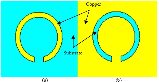
(a) (b)
Fig. 1. Normal edge couple split ring resonator, (b) Complimentary edge couple split ring resonator
The split ring resonator can be applied in many designs such as antennas [15-16], microwave absorber [17-18], filters [19], frequency selective surface [20] and others. There are many types of split ring resonator that have been designed by a few researchers. Edge coupled SRR (EC-SRR) was the initial first design by Pendry [21]. In this SRR design, there are two concentric metallic split rings, printed on a microwave dielectric circuit board. Figure 1 shows the different between normal and complimentary edge couple split ring resonator. The complementary of split ring resonator structure is obtained by replacing the copper parts with substrate material, and the substrate material with copper parts [22].
The second type is the broadside-couple SRR (BC-SRR). This design was proposed by Marques [23] to avoid the EC-SRR bianisotropy. It has the additional advantage of
potentially much smaller electrical size [24]. Another type of SRR design is nonbianistropic SRR (NB-SRR) that proposed by also by the same researcher. He had been designing this SRR to avoid EC-SRR bianistropy while keeping an uniplanar design. The other design by Marques was Double-Split SRR (DS-SRR). This is an alternative way to obtain inversion symmetry by introducing additional cuts in the EC-SRR design [25].
Spiral SRR (S-SRR) also is one of the designs that apply for SRR. This SRR design is a well-known resonator in planar microwave circuitry [26]. This design can provide a strong magnetic dipole at resonance, thus being useful for left-handed material (LHM) design. Open split ring resonator (O-SRR) had been introduced by [27]. The design consists of two copper rings that opening at the same side, not like before. The researcher claims that this design can be approximately 20 % smaller than normal split resonator. Other types of SRR structure is H-Shaped split ring resonator (HS-SRR) by [28] and twisted split ring resonator by [29].
II. BASIC ANTENNA DESIGN
This design was proposed by Marques [23] to avoid the EC- Patch antennas basically consist of a metal patch suspended over a ground plane. The microstrip patch antenna is the patch antennas that constructed on the dielectric substrates like FR4, Taconic or Duroid. Microstrip patch is the basic antennas that can be applied in various applications like Wireless Local Area Network (WLAN), Worldwide Interoperability for Microwave Access (WiMAX), and others. The advantages of microstrip patch antenna are its low profile, easy to fabricate, low cost, and omnidirectional radiation patterns [30]. The microstrip patch antennas were fed either by microstrip line or a coaxial probe through the ground plane in a variety of methods. Here, the design had been fed by the microstrip line at the bottom of the antenna.
TABLE I. DIMENSION OF NORMAL MICROSTRIP PATCH ANTENNA DESIGN
Part Symbol Dimension (mm)
Patch width Wp 51.5
Patch length Lp 38.7
Feed width Wt 1.00
Feed length Lp 19.0
Feed end width Wf 4.72
Feed end length Lf 7.70
Substrate/ground width Ws 60.0
Substrate/ground length Ls 80.0
Table I shows the dimension of the normal microstrip patch antenna. The antenna has three major parts – patch, feed
and feed end part. Feed line is located at the bottom of the antenna, connected the patch and the source signal (waveguide port). The four most popular feed techniques used are the microstrip line, coaxial probe, aperture coupling and proximity coupling [31]. In this antenna design, the line feeding is etched on the same substrate.
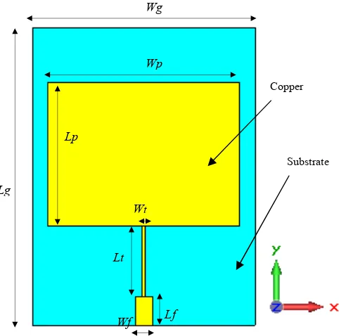
Figure 2 shows the schematic diagram of the basic microstrip patch antenna design. This design is simulated in CST Microwave Studio simulation software. The targeting frequency of this antenna is 2.4 GHz. This structure prints on the Roger RT/Duroid 5880 substrate with dielectric constant εr
=2.2. The dimension of the board is 60 mm width x 80 mm length. The ground plane is printed on the back side of the substrate with dimension of 60 mm width, Wg x 80 mm length,
Lg. A 50 Ω waveguide port is used to feed power into the radiator.
Fig. 2. Microstrip patch antenna design in CST Microwave Studio simulation software
III. SPLIT RING RESONATOR
There are many split ring resonator parameters that effect the performance of the microstrip patch antenna design. The example parameters are the split ring resonator shape, the gap between the split ring, the width of the rings, the number of split rings, and the size of the split ring resonator. This paper focuses on effect of different types of split ring resonator shapes. Figure 3 represents four types of complimentary split ring resonator shapes that used in the simulation. The shapes are square, circular, triangular and rhombic. All shapes have the same dimension of the gap between split ring and also the width of ring for parameter control. The dimension of the split ring resonator had been stated as - gap between split ring, Gr =
1.0 mm; width of split ring resonator, Ws = 3.93 mm; and
diameter of circular shape split ring resonator, Ds = 3.93 mm.
Lg
Lp
Wt
Lt
Wf Lf Wp Wg
Return Loss of Microstrip Patch Antenna
Frequency, GHz
2.0 2.2 2.4 2.6 2.8
Re
tu
rn
l
o
ss
,
dB
-35 -30 -25 -20 -15 -10 -5 0 5
Patch antenna - 10 dB line
Fig. 3. Single complementary split ring resonator structure of the antenna design with 4 different shapes – square, circular, triangular and rhombic
IV. ANTENNA INCORPORATED WITH SINGLE SRR
This section will focus the effect of the single split ring resonator structure on the microstrip patch antenna design. Four SRR patch antennas with different types of single complimentary split ring resonator had been incorporated into the previous designed.
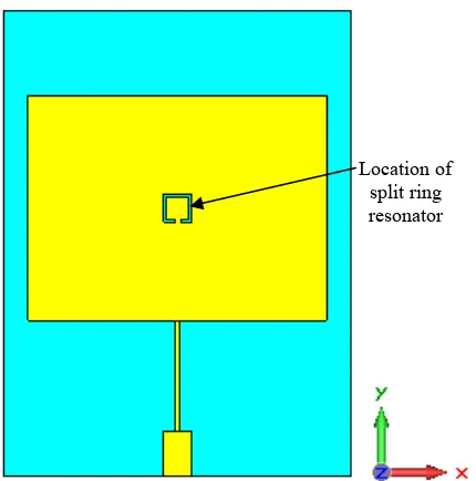
Fig. 4. The incorporated complimentary split ring resonator onto the center of the SRR patch antenna
Figure 4 shows the location of the split ring resonator at the center of the patch antenna and parallel with the feed line of the patch antenna. The dimension of this SRR antenna is same like normal antenna design. The central location cannot ensure the best return loss and gain performance of the antenna.
V. RESULT
The main parameters that consider in this study are return loss, gain and the impedance matching of the antenna. Return loss is a convenient step to characterize the input and output signal source. This section consists three simulation works – basic patch antenna, the effect of single complementary split ring resonator structure on patch antenna design and the location of split ring resonators on the antenna.
A. Basic Antenna Design
Figure 5 represents the return loss of normal microstrip patch antenna in CST Microwave Studio simulation software. The resonant frequency, fr for this antenna is 2.40 GHz with -
32.846 dB of return loss performance. The resonant frequency is the frequency where the capacitive and inductive reactances cancel each other. The bandwidth of this antenna is 51.0 MHz in the frequency range between lower frequency limit, fLand
higher frequency limit, fH. The value of fL = 2.374 GHz while
the fH = 2.425 GHz.
Fig. 5. Return loss of normal patch antenna (without single complimentary SRR structure).
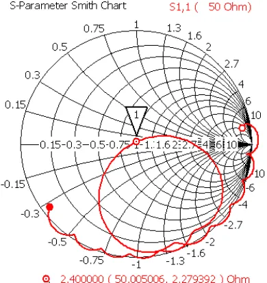
The result of 50Ω input impedance is shown by S-Parameter Smith Chart in Figure 6. As an electro-magnetic wave travels through the different parts of the antenna system it may encounter differences in impedance. The matching process is necessary to transform the antenna input impedance to the same value as the transmission line characteristic impedance. Without good impedance matching, some wave’s energy will reflect back to the source.
Figure 7 shows the location of the normal microstrip patch antenna in 3D view farfield. Figure 8 shows the 3D radiation pattern in CST Microwave Studio simulation software. The radiation patterns represent the electromagnetic power distribution in free space. It shows that the gain of this normal patch antenna is 6.334 dB.
Ws
Gr
Ds
Gr
Ws
Gr
Substrate Copper
Ws
Gr
Location of split ring resonator
fL fH
Fig. 6. Input impedance in S-Parameter Smith chart
Fig. 7. The location of the antenna and its directivity in CST Microwave Studio 3D view farfield
Fig. 8. Radiation pattern and gain of the patch antenna gain in CST Microwave Studio 3D view farfield
B. Patch Antenna Design with SRR structure
Figure 9 represents the return loss performance of the microstrip patch antenna with different shapes of single complimentary split ring resonator structure. From the observation, it shows that the addition of split ring resonator had shifted the frequency higher than 2.40 GHz. It also decreases the return loss compares to the normal patch antenna design. The -10 dB value of bandwidth for SRR patch antenna design are nearly similar compared to the normal patch antenna.
Fig. 9. Return loss of microstrip patch antenna with different shapes of single complimentary split ring resonator structure
Table II shows the comparison of the various performances between the normal patch antenna and SRR patch antenna. From the graph, the return loss of SRR antenna had decrease compared to the normal antenna but it improves the gain. By incorporating the SRR structure, it shifted the frequency resonant to a higher frequency compared to the normal patch antenna. It shows that the square patch antenna gives the highest impact to the patch antenna with 6.503 dB of gain, followed by triangular SRR with 6.404 dB.
TABLE II. COMPARISON OF PARAMETER PERFORMANCE RESULT BETWEEN THE NORMAL PATCH ANTENNA AND PATCH ANTENNA WITH SINGLE
COMPLIMENTARY SRR STRUCTURE
Single SRR shape
Resonant frequency, fr
(GHz)
Return loss (dB)
Bandwidth (MHz),
fL-fH (GHz)
Gain (dB)
No SRR structure
2.400 - 32.846 51 (2.374 – 2.425)
6.334
Square SRR 2.414 - 29.554 50 (2.390 – 2.440)
6.508
Circular SRR 2.416 - 24.221 48 (2.393 – 2.441)
6.394
Rhombic SRR
2.422 - 24.029 53 (2.396 –
2.449)
6.372
Triangular SRR
2.422 - 30.602 53 (2.396 –
2.448)
6.404 Return Loss of Microstrip Patch Antenna with Different Shapes of Single Complimentary Split Ring Resonator Structure
Frequency, GHz
2.30 2.35 2.40 2.45 2.50 2.55
Re
tu
rn
l
o
ss
,
d
B
-35 -30 -25 -20 -15 -10 -5 0 5
C. Effect on SRR location
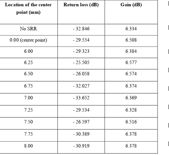
Figure 10 and Table III shows the effect of the square shape split ring resonator location on the microstrip patch antenna. The SRR can be shifted in the range between 6 mm and 8 mm left from the center of the patch antenna. This range not effected the frequency of the antenna design that is 2.414 GHz. The 7 mm shifting from the center had shown an improvement of return loss to - 33.652 dB. The highest gain achieved at 6.25 mm from center of 6.577 dB compared to SRR at center point by only 6.508 dB.
Fig. 10. Return loss of microstrip patch antenna with different location of single complimentary split ring resonator structure
TABLE III. THE RETURN LOSS GAIN AND GAIN PERFORMANCE WITH DIFFERENT LOCATION OF SINGLE SQUARE SRR ON PATCH ANTENNA
Location of the center point (mm)
From the simulation work using CST Microwave Studio, the single complimentary split ring resonator had been improved the focusing parameter in this paper. The gain of the antenna shown an increased compared to the normal patch antenna. The different split ring resonator shapes improved the return loss, and radiation pattern.
In the future works, the antenna design can be improved by adding the N-number rings, adding the array split ring resonator or define the other new design of split ring resonator into the microstrip patch design.
REFERENCES
[1] M. Z. M. Zani, M. H. Jusoh, A. A. Sulaiman, N. H. Baba, R. A. Awang, M. F. Ain, “Circular Patch Antenna on Metamaterial, Electronic Devices,” 2010 International Conference on Systems and Applications (ICEDSA), pp. 313-316, 2010.
[2] A. Gummalla, C. -J. Lee, M. Achour, “Compact Metamaterial Quad-band Antenna for Mobile Application,” International Symposium on Antennas and Propagation Society, pp. 1-4, 2008.
[3] A. Feresidis, J. C. Vardaxoglou, “Flat Plate Millimeter Wave Antenna Based on Partially Reflective FSS,” International Conference on Antennas and Propagation, vol. 1, pp. 33-36, 2001.
[4] M. J. Al-Hasan, T. A. Denidni, A. Sebak, “A New UC-EBG Based-dielectric Resonator Antenna for Millimeter-wave Applications,” 2011 IEEE International Symposium on Antennas and Propagation (APSURSI), pp. 1274-1276, 2011.
[5] R. Alkhatib, M. Drissi, “EBG Antenna for Microwave Links Applications,” 2nd Information and Communication Technologies (ICTTA '06), vol. 2, pp. 2190-2194, 2006.
[6] O. Ayop, M. K. A. Rahim, M. R. Kamarudin, M. Z. A. Abd Aziz, M. Abu, “Dual Band Electromagnetic Band Gap Structure Incorporated with Ultra-wideband Antenna,” 2010 Proceedings of the Fourth European Conference on Antennas and Propagation (EuCAP), pp. 1-4, 2010.
[7] D. N. Elsheakh, H. A. Elsadek, E. A. Abdallah, M. F. Iskander, H. Elhenawy, “Ultrawide Bandwidth Umbrella-Shaped Microstrip Monopole Antenna Using Spiral Artificial Magnetic Conductor (SAMC),” vol. 8, pp. 1255-1258, 2009.
[8] A. Foroozesh, L. Shafai, “Effects of Artificial Magnetic Conductors in the Design of Low-Profile Gain Planar Antennas With High-Permittivity Dielectric Superstrate,” IEEE Antennas and Wireless Propagation Letters, vol. 8, pp. 10-13, 2009.
[9] A. Erentok, P. L. Luljak, R. W. Ziolkowski, “Characterization of a Volumetric Metamaterial Realization of an Artificial Magnetic Conductor for Antenna Applications,” IEEE Transactions on Antennas and Propagation, vol. 53, issue 1, part 1, pp. 160-172, 2005.
[10] W. Y., Qiang, F. Tao, “The Study on a Patch Antenna with PBG Structure,” Third International Symposium on Intelligent Information Technology Application (IITA 2009), vol. 3, pp. 565-567, 2009. [11] N. Singh, S. Singh, R. K. Sarin, “Effect of Photonic Band Gap Structure
on Planar Antenna Configuration,” 2010 Mediterranean Microwave Symposium (MMS), pp. 81-85, 2010.
[12] S. S. Patel, Y. P. Kosta, “Multiband PBG Suspended Patch Antenna,” 2011 3rd International Conference on Electronics Computer Technology (ICECT), vol. 2, pp. 5-9, 2011.
[13] V. G. Veselago, “The Electrodynamics of Substances with Simultaneously Negative Values of Permittivity and Permeability,” Soviet Physics USPEKI, vol. 10, no. 4, pp. 509-514, 1968.
[14] D. R. Smith, W. J. Padilla, D. C. Vier, S. C. Nemat-Nasser, S. Schultz, “Composite Medium with Simultaneously Negative Permeability and Permittivity,” Phys. Rev. Lett., vol. 84, pp. 4184–4187, 2000.
[15] A. A. M. Ezanuddin, F. Malek, P. J. Soh, “Investigation of Complementary Split Ring Resonators with Dielectric Ring,” 2010 Loughborough Antennas and Propagation Conference (LAPC), pp. 297-300, 2010.
Return Loss of Microstrip Patch Antenna with Different Location of Single Complimentary Split Ring Resonator Structure
Frequency, dB
2.40 2.41 2.42 2.43 2.44
[16] H. A. Majid, M. Rahim, T. Masri, “Left Handed Metamaterial Design For Microstrip Antenna Application,” IEEE International RF and Microwave Conference (RFM 2008), pp. 218-221, 2008.
[17] H. Nornikman, F. Malek, P. J. Soh, A. A. H. Azremi, “Design a Rice Husk Pyramidal Microwave Absorber with Split Ring Resonator,” The Asia-Pacific Symposium on Applied Electromagnetics and Mechanics 2010 (APSAEM 2010), 2010.
[18] H. Nornikman, B. H. Ahmad, M. Z. A. Abdul Aziz, F. Malek, H. Imran, A. R. Othman, “Study and Simulation of Edge Couple Split Ring Resonator (EC-SRR) on Truncated Pyramidal Microwave Absorber,” Progress In Electromagnetics Research (PIER), vol. 127, pp. 319-334, 2012.
[19] S. Das, A. Kundu, S. Maity, S. Dhar, B. Gupta, “Novel Compact CPW Filter for MICs Using Metamaterial Structures,” 2011 11th Mediterranean Microwave Symposium (MMS), pp. 286-289, 2011. [20] D. J. Kern, D. H. Werner, A. Monorchio, L. Lanuzza, M. J. Wilhelm,
“The Design Synthesis of Multiband Artificial Magnetic Conductors using High Impedance Frequency Selective Surfaces,” IEEE Transactions on Antennas and Propagation, vol. 53, issue 1, part 1, pp. 8 -17, 2005.
[21] J. B. Pendry, A. J. Holden, D. J. Robbins, W. J. Stewart, “Magnetism From Conductors and Enhanced Nonlinear Phenomena,” IEEE Trans. Microwave Theory Tech., vol. 47, pp. 2075-2084, 1999.
[22] H. Zhang, Y. Q. Li, X. Chen, Y. Q. Fu, N. C. Yuan, N. C., “Design of Circular Polarization Microstrip Patch Antennas with Complementary Split Ring Resonator,” 2008 International Workshop on Metamaterials, pp. 360-362, 2008.
[23] R. Marques, R. Medinaand, E. I.Raffi, “Role of Bi-anistropy in Negative Permeability and Left-handed Metamaterials,” Phys. Rev. B, vol. 65, paper 144441, 2002 .
[24] R. Marques, F. Mesa, J. Martel, F. Medina, “Comparative Analysis of Edge and Broadband Coupled Split Ring Resonator: Analytical Solution and Numerical Simulations,” Microwave Opt. Tech. Lett., vol. 44, pp. 133-137, 2003.
[25] R. Marques, J. D. Baena, J. Martel, F. Medina, F. Falcone, M. Sorolla, F. Martin, “Novel Small Resonant Electromagnetic Particles for Metamaterial and Filter Design,” Proc. ICEAA 2003, pp. 439–442, 2003 [26] J. D. Baena, R. Marques, F. Medina, J. Martel, “Artificial Magnetic
Metamaterial Design by using Spiral Resonator,” Physic Rev. B. vol. 69, paper 01442, 2004.
[27] S. S. Karthikeyan, M. Arulvani, “Double Negative Metamaterial Design Using Open Split Ring Resonator,” 2010 IEEE Students' Technology Symposium (TechSym), pp. 142-145, 2010.
[28] Machac, J., Rytir, M., Protiva, P.; Zehentner, J., “A Double H-Shaped Resonator for an Isotopic ENG Metamaterial,” 38th European Microwave Conference (EuMC 2008), pp. 547-550, 2008.
[29] D. A. Powell, K. Hannam, I. V. Shadrivov, Y. S. Kivshar, “Interaction of Twisted Split Ring Resonators,” 2011 Conference on and 12th European Quantum Electronics Conference, pp. 1, 2011.
[30] C. A. Balanis, “Antenna Theory Analysis and Design,” John Wiley, Inc., New Jersey, 2005.