(b) (a)
Rectangular Microstrip Patch Antenna Based on
Resonant Circuit Approach
Z. Zakaria, W. Y. Sam, M. Z. A. Abd Aziz and M. A. Meor Said
Centre for Telecommunication Research and Innovation (CeTRI), Department of Telecommunication Engineering Faculty of Electronic and Computer Engineering, Universiti Teknikal Malaysia Melaka (UTeM)
Hang Tuah Jaya 76100 Melaka, Malaysia.
E-mail: [email protected], [email protected], [email protected], [email protected]
Abstract—This paper presents the investigation based upon the resonant circuit approach to characterize the rectangular microstrip patch antenna from the low-pass prototype lumped element. The physical layout of the rectangular microstrip patch antenna based on single-mode and dual-mode will be established. An improvement on bandwidth of the antenna can be achieved by increasing the number of modes. In the paper, the understanding of microwave filter synthesis technique is applied in order to obtain the resonance at 2 GHz. A notch technique is used in the design to produce dual-mode frequencies on the microstrip patch antenna. The prototype circuit and proposed physical layout of the single and dual-mode microstrip patch antennas are demonstrated through the analysis of circuit and EM simulations in order to proof the proposed concept. This study would be useful to realize antenna for broadband applications as well as to investigate the appropriate technique for integrating antenna and microwave filter.
Keywords-Rectangular microstrip patch antenna; Single-mode Antenna; Dual-mode Antenna; Microwave Filter.
I. INTRODUCTION
The rapid development of wireless applications ranging from Bluetooth, WLANs, GSM, LTE, satellite and military applications requires more efficient, low profile and flexible antennas. Microstrip patch antennas are generally used in communication systems for their benefit of ease of fabrication, low profile, lighter in weight and low cost [1]. However, there is a limitation on its performance for a microstrip patch antenna in term of narrow bandwidth [1][2]. The most well-known method was proposed to overcome the limitation is by increasing the height of the substrate [3]. However, this method increases the complexity and suffers from the power loss. In [4], the antenna was designed with modified circle-like slot was used on the elements. However, etching two L-shaped slots on the ground are slightly complex to design on the antenna especially come to 50 Ω impedance matching.
In this paper, a development of the rectangular microstrip patch antenna based on microwave filter circuit theory is presented. The rectangular microstrip patch antennas are designed at resonant frequency of 2 GHz for single and dual-mode. The advantages of this technique are the realization of microstrip patch antenna that can be transformed for broadband applications and also can be applied to the integration technique between antenna and microwave filter.
II. EQUIVALENT CIRCUIT DESIGN
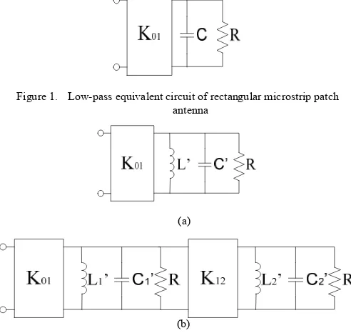
In this section, a low-pass filter prototype equivalent circuit is used to produce single-mode antenna equivalent circuit as shown in Fig. 1. The inverter, K01 represents the coupling mechanism between the input port and the resonance circuit [5]. In Fig 2 (a) shows the equivalent circuit of single-mode based on the low-pass prototype circuit shown in Fig. 1. Similarly the dual-mode antenna equivalent circuit as shown in Fig. 2 (b) can be developed based on the second order of the low-pass prototype circuit. The dual-mode antenna equivalent circuit can also be developed based on a combination of two single-mode equivalent circuit.
Figure 1. Low-pass equivalent circuit of rectangular microstrip patch antenna
Figure 2. (a) Single-mode circuit of the rectangular microstrip patch antenna (b) Dual-mode circuit of the rectangular microstrip patch antenna The impedance inverter Kr, r+1 and the capacitance Cr value of the low-pass prototype can be determined using [6]:
sin (1)
, / /
(2) 2012 IEEE Symposium on Wireless Technology and Applications (ISWTA), September 23-26, 2012, Bandung, Indonesia
where N, is the number of order of the n defined as [6]:
while is the ripple of insertion loss. The a circuit can be transformed from the lo equivalent circuit using [6]:
where is the geometric midband freq bandwidth scaling factor and the r is the num resistances, R acts as load of the prototype ci
III. RECTANGULAR MICROSTRIP PAT The transformation from the antenna eq physical realization is implemented u microstrip patch antenna technology. The d rectangular microstrip patch antenna can d width, w, and the length, L, as shown in Fig.
√
where is center frequency and permeability. ΔL extended incremental lengt be calculated using the equation below [7]:
∆ .4 . . .
h is the thickness of the dielectric substra calculated using this formula [7]:
/
Figure 3. Top view rectangular microstrip p where R is the impedance and is the i shown in Fig. 3. The dual-mode frequen
network and η, is
(3)
antenna equivalent w-pass prototype
(4)
(5)
quency; is the mber of order. The ircuit.
TCH ANTENNA quivalent circuit to using rectangular
dimensions of the determined by the
3, using [7]:
(6)
(7)
is the efficient th of the patch can
. (8)
ate and can be
(9)
atch antenna
inset feed line as ncy of rectangular
microstrip patch antenna is re notch concept that will be expla
IV. SIMULA A. Single mode
In this section, the single-m has been designed at 2 GHz us the coupling value, K01 of 50, inductance, C’ = 63.98 pH.
Fig. 4 shows the simulated r circuit. It shows that the return dB and a -10 dB bandwidth achieved.
Figure 4. Simulation results of equi m The antenna equivalent circu been simulated using Advanc CST Microwave Studio in o concept. The device is constru dielectric substrate thick with The thickness of copper is 0.0 0.019. The dimension of the antenna can be determined usin length, L, and width, w, of the 48.79 mm respectively. The an with 50 Ω feed line.
Fig. 5 shows the effect o varying the length, L, of the mi EM simulations using CST. 32.7184 mm gives good re resonance of 2 GHz. This i indicates that at 2 GHz the re with a -10 dB bandwidth appro obtained.
ealized by simply introducing a ained in next section.
ATION RESULTS
mode antenna equivalent circuit ing equations (1) – (5) to obtain capacitance, L’ = 98.98 pF and
results of the antenna equivalent n loss, S11, with better than -30 of around 31 MHz have been
ivalent ideal circuit antenna for single-ode
uit and the physical layout have ced Design System (ADS) and order to validate the proposed ucted using FR-4 on a 1.6 mm permeability constant = 4.6. 035 mm and the loss tangent is e rectangular microstrip patch ng equations (6) – (9). Thus, the
patch antenna are 32.4 mm and ntenna is connected to input port
on the resonant frequency by icrostrip patch antenna based on
It shows that the length of sponse on the return loss at is summarized in Table I. It eturn loss has achieved -30 dB oximately of 39.9 MHz has been 2012 IEEE Symposium on Wireless Technology and Applications (ISWTA), September 23-26, 2012, Bandung, Indonesia
Figure 5. EM Simulation results of microstrip patch an TABLE I. SIMULATION RESULTS FOR SINGLE-M MICROSTRIP PATCH ANTENNA
Frequency
Similarly for the dual-mode and using eq the antenna equivalent circuit can be design coupling values, K01 of 50, and K12 of 55 capacitance, C1’ = C2’ = 42.436 pF and indu 149.225 pH. Fig. 6 shows the simulated resu equivalent circuit. It shows that the return lo than -12 dB and a -10 dB bandwidth of arou been achieved.
The antenna equivalent circuit and the ph been simulated using Advanced Design Sy CST Microwave Studio in order to valid concept. The device is constructed using F dielectric substrate thick with permeability The thickness of copper is 0.035mm and t 0.019. The dimension of the rectangular antenna can be determined using equations ( length, L, and width, w, of the patch antenna 70.6 mm respectively. The antenna is conne with 50 Ω feed line. The size of the notch to mode response is 18 mm x 2 mm is show found that antenna having an appropria resonates at two different frequencies but w on the bandwidth as shown in Fig. 8.
-40 5.2765, while the uctance, L1’ = L2’ =
ults of the antenna oss, S11 with better und 82 MHz have
hysical layout have ystem (ADS) and date the proposed FR-4 on a 1.6mm y constant εr =4.6.
the loss tangent is microstrip patch (6) – (9). Thus, the
a are 30.5 mm and ected to input port o produce a dual - wn in Fig. 7. It is
te size of notch with improvement
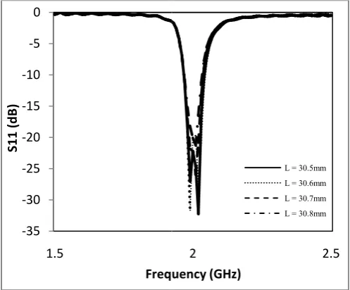
Fig. 8 shows the effect o varying the length, L, of the mi EM simulations using CST. It s mm gives a good response to th 1.988 GHz and 2.023 GHz res the variations of length, L, with center frequency of 2 GHz, the -23 dB and a -10dB bandwidt have been obtained.
Figure 6. Simulation results of equ m
Figure 7. The physical layer of mic
dual-Figure 8. EM Simulation results of m 2.4
on the resonant frequency by icrostrip patch antenna based on shows that the length, L, of 30.5 he return loss and resonances at spectively. Table II summarizes h its response. It indicates that at e return loss, S11 with better than th approximately of 76.87 MHz
uivalent ideal circuit antenna for dual-ode
crostrip patch antenna with a notch for -mode
microstrip patch antenna for dual-mode
2 2.5 2012 IEEE Symposium on Wireless Technology and Applications (ISWTA), September 23-26, 2012, Bandung, Indonesia
TABLE II. SIMULATION RESULTS FOR DUAL-MODE RECTANGULAR MICROSTRIP PATCH ANTENNA
Dual-Frequency
(GHz) Return loss (dB)
Length, L (mm)
Bandwidth (MHz)
1.988 & 2.023 -44.25 & -31.60 30.5 76.87 1.989 & 2.018 -27.23 & -42.01 30.6 73.24 1.990 & 2.012 -21.81 & -26.65 30.7 69.03 1.989 & 2.008 -18.04 & -21.41 30.8 64.53
Fig. 9 shows the radiation pattern for the single-mode antenna at 2 GHz. The pattern represents the main lobe magnitude of 4.9 dB at 2.0 degree direction from the origin point. While Fig. 10 shows the radiation pattern for the dual-mode antenna at the resonance of 2 GHz. The main lobe magnitude of 4.7 dB at 1.0 degree direction from the origin point can be observed.
Figure 9. Simulated radiation pattern for single-mode at frequency 2 GHz
Figure 10. Simulated radiation pattern for dual-mode at center frequency 2.003 GHz
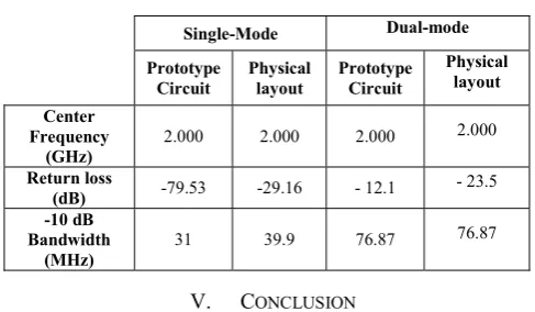
The comparison between single- and dual-mode antennas can be seen in Table III. It shows that the bandwidth of the microstrip patch antenna can be improved through dual-mode
response. However further analysis and investigation on the fabrication of the single- and dual-mode antennas need to be carried out in future works.
TABLE III. COMPARISON RESULTS BETWEEN SINGLE-MODE AND DUAL-MODE FOR RECTANGULAR MICROSTRIP PATCH ANTENNA
Single-Mode Dual-mode
Prototype Circuit
Physical layout
Prototype Circuit
Physical layout
Center Frequency
(GHz)
2.000 2.000 2.000 2.000 Return loss
(dB) -79.53 -29.16 - 12.1 - 23.5 -10 dB
Bandwidth (MHz)
31 39.9 76.87 76.87
V. CONCLUSION
A new technique to produce dual-mode rectangular microstrip patch antenna based on resonant circuit approach has been developed. The EM simulated results show good agreements with the ideal circuit. The main advantage of this technique is the antenna can be systematically designed to improve the bandwidth of the response. This study is also useful for the design of broadband antenna applications as well as to realize integration between the antenna and microwave filter in a single device.
ACKNOWLEDGMENT
W. Y. Sam would like to thank UTeM and MyBrain15 program for sponsoring his study.
REFERENCES
[1] Vishwakarma, R.K.; Kumar, R.; ,"Rectangular notch microstrip antenna for dual-band operation," Recent Advances in Microwave Theory and Applications, 2008 International Conference on
Microwave, pp.675-677, 21-24 Nov. 2008.
[2] Chew, W.C.; Liu, Q.; , "Resonance frequency of a rectangular microstrip patch," IEEE Transactions onAntennas and Propagation,
vol.36, no.8, pp.1045-1056, Aug 1988.
[3] Dubey, M.; Bharadwaj, D.; Saini, J.S.; Saxena, V.K.; Jain, R.; Bhatnagar, D.; , "Dual frequency rectangular patch antenna with a rectangular notch for improved bandwidth performance," Recent Advances in Microwave Theory and Applications, 2008 International
Conference on Microwave., pp.809-811, 21-24 Nov. 2008.
[4] Emadian, R.; Mirmozafari, M.; Ghobadi, C.; Nourinia, J.; , "Bandwidth enhancement of dual band-notched circle-like slot antenna," Electronics Letters , vol.48, no.7, pp.356-357, March 29 2012.
[5] Abunjaileh, A.I.; Hunter, I.C.; Kemp, A.H.; , "Application of dual-mode filter techniques to the broadband matching of microstrip patch antennas," Microwaves, Antennas & Propagation, IET , vol.1, no.2, pp.273-276, April 2007.
[6] Ian Hunter, Theory and Design of Microwave Filters, The Institution of Electrical Engineers, 2001.
[7] C. A. Balanis, Antenna Theory: Analysis and Design, 3rd edition,
Wiley, 2005.
2012 IEEE Symposium on Wireless Technology and Applications (ISWTA), September 23-26, 2012, Bandung, Indonesia