DOI: 10.12928/TELKOMNIKA.v12i4.136 933
Two-Dimensional Imaging Algorithm Based on Linear
Prognosis for Space Target in Bistatic ISAR System
Xueping Lu*, Shapu Ren Shaoxing University, Zhejiang, 312000, China *Corresponding author, e-mail: [email protected]
Abstract
In bistatic inverse synthetic aperture radar (Bi-ISAR) system, its image resolution is lower than monostatic ISAR system. In order to solve this problem, the linear prognosis algorithm is adopted in the imaging process and the imaging algorithm based on linear prognosis is proposed. Space target Bi-ISAR imaging is taken as example in the research. The one-dimensional range profile is created through pulse compression mehod. Before the azimuth compression, burg entropy maximum algorithm in Levions recursive method is used to estimate the prognosis coefficients and the azimuth echo data. Then Fourier transformation is used to compress the azimuth data in order to get the high resolution azimuth image. This imaging method can obtain the two-dimensional image with the resolution equal to the monostatic ISAR or even higher than it. Simulation experiments have verified the effectiveness and availability of the algorithm.
Keywords: bistatic ISAR, levions prognosis, image resolution, two-dimensional imaging
1. Introduction
Due to the separated transmitting and receiving station, the bistatic Inverse Synthetic Aperture Radar (ISAR) can still get the 2--D (two-dimensional) object image even when the relative radar line of sight has no rotational movement, which is the better characteristic than monostatic ISAR. So, bistatic ISAR has the higher imaging probability than monostatic ISAR [1],[2]. Otherwise, when the receiving station is located in the front, the imaging range augments at the same time, which could improve the detection and imaging ability for stealth targets [3]-[5]. In recent years, the main research of bistatic ISAR is focused on imaging principle and various compensation algorithms [6]-[9].
During the bistatic ISAR imaging process, the time-variant bistatic angle can lead to a time-variant bistatic imaging resolution, which makes the 2-D image become blurred [10]. The movement of space targets is complicated, so it needs to image the object in a short integration time and avoid blurring phenomenon of 2D image.
Because of the short integration time, the bistatic angle and image resolution can be looked as the constant during imaging time, which could effectively avoid phenomenon of image blurring. At the same time, the target characteristics have relatively small changes when imaging during small rotation angel, which can decrease the difficulty of movement compensation. While the coherent integration time becomes shorter, the resolution is definitely decreased. So it is the prerequisite to research the ISAR imaging algorithm when the rotation angle is small.
high resolution, small calculation works and the higher possibility of realization. So the second method is adopted in this paper to research the 2-D imaging algorithm for bistatic ISAR according to space targets.
2. Echo modeling of space target in bistatic ISAR system
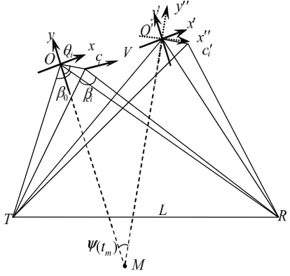
The imaging geometry relationship of moving target in bistatic ISAR system is showed in Figure 1.
( )
t
mFigure 1. Geometry relationship of bistatic ISAR
In Figure 1, L is the baseline of bistatic radar; T is transmitting station; R is receiving station; y axis is the bisector of target when starting the observation and is the range direction of bistatic radar also; 0 is bistatic angle; ci is the bistatic angle of scatter ci in target, and
0 ci
is thought to be correct dot O is the center of phase; ci is the angle between position vector Oci of scatter and the negative direction of y axis; V is the target velocity; tm is the rotation angle of bisector during imaging process. If we make the assumption that the bistatic radar is ideally synchro and LFM signal is transmitted with the echo which is sampled in intermediate frequency and desample it to baseband frequency, the echo of scatter ci can be denoted through (1) as follows.
2
0
ˆ ( ) ˆ,
( ) ( )
ˆ exp 2 exp
ci m rci m ci
p
ci m ci m
t R t c s t t rect
T
R t R t
j f j t
c c
(1)
Where tˆ is the time-in-pulse; tm is the pulse transmitting time; f0 is carrier frequency; is frequency slope; Tp is pulse width; ci is the non-back scattering intensity of scatter ci in the ith range bin.
( ) ( ) ( )
( ) ( ) 2 cos[ ( )]cos[ ]
2 ci m ref m roti m
m ref m i ci m
R t R t R t
t
R t r t
(2)
Where tm mT m
0,1, 2,
is slow-time; ( )tm is target time-varying bistatic angle during the imaging process; Rref( )tm is the range course between target phase center and transmitting-receiving station, which is the translational movement item of target; Rroti( )tm is therotational range item of scatter
c
i. It can be found from type (2) that in bistatic ISAR imaging, the range transformation can still be divided into two parts, i.e, translational movement item( ) ref m
R t and rotational movement item Rroti( )tm . So through bistatic ISAR system also can get the target image through range compression, range alignment, initial phase correction, azimuth compression just as monostatic ISAR system researched in the paper [6].
When the rotational angle is small which is equal to integration of short time, the bistatic angle ( )tm can be thought as the constant approximately. It is assumed that the constant bistatic angel is thought to be 0. If the translational range item Rref( )tm has been totally compensated, the range transformation item of scatter ci can be simplified as type (3)
0
( ) 2 cos[ ( )] cos[ ] 2
ci m i ci m
R t r t (3)
At this time, target range resolution of and azimuth resolution can be expressed as types (4), (5) respectively, the expressions are accordance with the research work in the paper [14].
0
2 cos 2
r w c B
(4)
0
2 cos 2
a rot
(5)
In the equations mentioned above, Bw is the transmitting signal bandwidth; rot is the rotational angle of bisector during imaging process. From types (4) and (5), it can be found that when the transmitting signal bandwidth is fixed, the target range resolution in small rotation angle imaging condition is the constant. But the azimuth resolution is totally determinded by rotational anglerot. When the imaging rotational angle rot is small, the azimuth resolution is also small as well, which could not satisfy with the demands of imaging system. So the imaging algorithm in small rotational angle condition should to be researched and improved.
3. Analysis of Bistatic ISAR resolution
As transmitting station and receiving station are separated from each other in bistatic ISAR system, thus the imaging resolution is related with bistatic angle. If the imaging bistatic angle is , then the target range resolution can be expressed as following type (6) [14],[15].
_ 0
2 cos 2
rc w c B
(6)
It can be found from type (6) that as there exists bistatic angel, the bistatic ISRA range resolution is lower than the monostatic ISAR range resolution c 2Bw with the same signal bandwidth. For the convenience of comparison, bistatic ISRA system is thought to be an equivalent monostatic ISAR system in the bisector. If the transmitting carrier frequency is f0, signal bandwidth is Bw, bistatic angle is , then the equivalent carrier frequency of monostatic
radar is f0 f0cos
2
and the equivalent signal bandwidth is BBwcos
2
. So the resolution also could be expressed as type (6) reported in the paper [15]. This equivalent model can explain why the range resolution is decreased with bistatic angel, so this model has been widely used during the existent bistatic ISAR research work of the papers [13]-[15].The frequency of echo could not be changed except Doppler effects of target. And the target scattering echo frequency and its bandwidth could not be changed as the existence of bistatic angle. So, there must be some causes that make the bistatic range resolution different from that of monostatic ISAR system. In the Figure.1, it is shown that the wave distance is different from scatter c1 and c2 in different range areas.
2
c
1
c
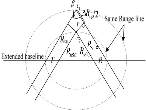
Figure 2. Wave distance difference
In the Figure 2, the broken line is the range-same line of bistatic radar. Rtc10,Rrc10denote the distance between scatter c1 and transmitting, receiving stations, respectively. Rtc20,Rrc20
represent the distance between scatter c2 and transmitting, receiving station, respectively. is bistatic angle; T、R are transmitting and receiving station respectively;
r
is the radial distance between scatterc
1 andc
2. When the target is far from radar, the assumption of far field is satisfied. So the wave-frontier is thought to be plane-wave. The wave distances between transmitting, receiving stations and scatter are parallel. Under this assumption, the round wave distance difference Rwp between scatter c1 and scatterc
2 can be expressed as below.2 cos
2
wp
R
r
(7)the time-delay of the two scatters echo after pulse compression is 3dB width at least. And the round wave distance difference d could be denoted as below type (8).
w
c
d
B
(8)
The range resolving ability is the width of the smallest resolving range in the targets. The bistatic range-bin width is determinded by the distance between the two intersection dots, which are the dots of bistatic bisector intersected by the two rang-same lines with the same focus which is also verfied by the paper [16],[17]. The distance between the two dots is also the distance between the two range-same lines. So, when the target round wave distance difference in the type (7) is the same as showed in type (8), scatter c1 and scatter c2 can be separated in range axis by the square. And now, the distance difference of the two scatters in range axis is rc_ 0, which is expressed in the type (6). The resolution is lower than the monostatic ISAR system with the same signal bandwidth asr c 2Bw
4. Imaging algorithm based on levions prognosis 4.1 Imaging flow of 2-D image
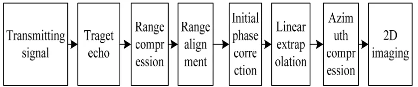
The main effect factor of 2-D imaging in small rotational angle is the azimuth resolution. So in the following research, it is assumed that one-dimensional range profile is obtained through digital matching filter pulse compression and the translational compensation has been accomplished.
The ISAR imaging problem can be regarded as spectrum estimation problem just same as the paper [11]. The basic step of linear prognosis is firstly to estimate the filter coefficients and then extrapolate the data to the needed extent. The prognosis coefficients are estimated based on the least mean square error rule, which can ensure the difference value between actual echo and the extrapolated data is the least. In order to improve the azimuth spectrum estimation resolution, the range echo is estimated to accord with the linear prognosis model and the azimuth data integration time is extended , so the azimuth resolution is advanced.
If some range aligned range echo could be expressed as
x t(n m ),, (x tn1)
, so the extrapolated echo at time tn of this range could be expressed as
1
( ) ( ) ˆ
m
n m n i
i
x t a i x t
(9)In the equation (9), a im( ) is the ith coefficient of the m-order filter. With the same
analysis, the echo at time tn m 1 after extrapolated of this range echo could be expressed by (10).
*1 1
( ) ( )
ˆ
m
n m m n m i
i
x t a i x t
(10)In the equation(10), *( )
m
a i is the conjugate complex of a im( ).
If the former-latter prognosis is prosecuted by
p
times, then the echo after prognosis could be expressed as
x t(n m p), , (x tn m ), , (x tn1), , (x tn 1p)
. If the pulse repeat cycle is T, thenthe azimuth resolution could be improved from 1mT to 1T m( 2 )p .
Figure 3. 2D imaging algorithm flow
4.2 Construction of prognosis filter coefficients and its order
The larger the linear prognosis filter is, the more accurate the prognosis result is. But the calculation amount is increased rapidly also, so the balance between calculation work of algorithm and prognosis error is destroied. In the paper [17], it shows that when the Auto Regressive (AR) model is used to extrapolate data, the most accurate prognosis results could be obtained when the filter order is chosen to be 1/3 of the data length. The Levinson prognosis of Burg entropy is used to estimate the filter order and its coefficients. The filter coefficients of different filter order are estimated firstly, then the prognosis error power with different filter is compared and it chooses the filter with the smallest prognosis error power.
The basic steps to get the prognosis order and its coefficients are summarized as follows.
Step1 Initial the prognosis power error and its back-and-forth prognosis error; Step2 Count the reflection coefficient Km that is used to extrapolate data; Step3 Count the back-and-forth prognosis filter coefficients via (11);
*
1 1
( ) ( ) ( ), 1, , 1 ( )
m m m m
m m
a i a i K a m i i m
a m K
(11)
Step4 Count the prognosis error power of the filter with m-order via (12)
2 1
(1 )
m m m
P K P (12)
Step5 Count the output of the filter with m-order, repeat Step2 to Step5 until the prognosis error power Pm hardly become smaller. And the order and coefficients of prognosis filter are got at the same time.
4.3 Data extrapolation length
5. Simulation experiment
Simulation situation and scatter model are expressed in Figure 4 and Figure 5, respectively.
Figure 4. Target moving simulation scene
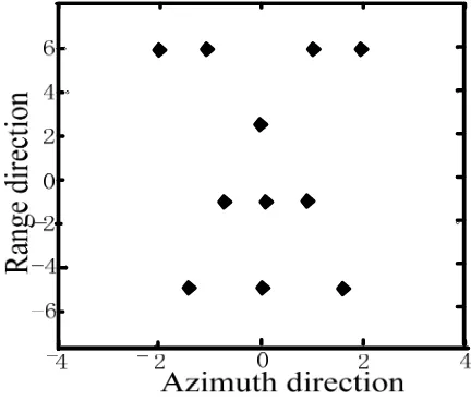
Figure 5. Target scatter model
obtined through radar equation. In the simulation, the smallest receiving SNR is set to be 14dB and the target RCS is set as 4m2. Because the scatters are separate, respectively, so the RCS of every concrete scatter is 0.5m2. Simulation parameters of the radar system are shown in the Table 1.
Table 1. Simulation radar parameters
parameter index parameter index Bistatic angel 120 Imaging angel 2
Signal width 950MHz Pulse width 60s Carrier
frequency 8GHz
Baseline
length 200Km
According to the parameters in Table 1, the range resolution and azimuth resolution can be expressed as
r 0.33 and
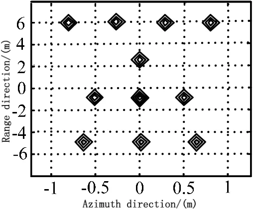
a 0.8596 respectively, through type (4), (5). Simulation results are shown in Figure 6 and Figure 7.Figure 6. 2-D image before azimuth data extrapolation
From the Figure 6 we can find that, before the azimuth data extrapolation range resolution is smaller than the interval of scatters so the scatters could be totally differentiated from range profile. But the azimuth resolution is not small enough, so the scatters could not be differentiated clearly form azimuth direction. Figure 6 is the 2-D image after data extrapolation and because the azimuth doppler resolution is improved, so the scatters could be totally differentiated from azimuth direction,and the correct 2-D image is obtained.
6. Conclusion
ISAR imaging could be seen as high-resolution spectrum estimation problem after the movement compensation is completed. The space target bistatic 2-D imaging problem in small rotation angle is researched in the paper. Simulation results prove that this algorithm can improve resolution in azimuth direction and can be used in practical environment.The research on how the algorithm can be used in lower SNR is also performed.
References
[1] Marco Martorella,James Palmer John Homer Brad Littleton I. Dennis Longstaff. On Bistatic , , ,
Inverse Synthetic Aperture Radar. IEEE Transactions on AES. 2007; 3: 1125-1134.
[2] Delisle GY.,Haiqing Wu. Moving target imaging and trajectory computation using ISAR. IEEE Transactions on AES. 1994; 30(3): 887-899.
[3] Chen VC.,Shie Qian. Joint time-frequency transform for radar range-Doppler imaging. IEEE Transactions on AES. 1998; 34(2): 486-499.
[4] Liu Xin, China, Ren Yongfeng, Chu Chengqun. Application of Selfadapting Radar Video Echo Acquisition System based on LZW Algorithm. TELKOMNIKA Indonesian Journal of Electrical Engineering. 2014; 12(2): 1333-1342.
[5] Xue-tao Yu, Xiao-ping Rui, Feng Li. Localization Methods of Weighted Centroid of dBZ on WeatherRadar Echo Maps in Vector Format. TELKOMNIKA Indonesian Journal of Electrical Engineering. 2013; 11(2): 1033-1040.
[6] Jingfang Wang. Multitarget Direction Measurement on Bistatic MIMO Radar. TELKOMNIKA Indonesian Journal of Electrical Engineering. 2014; 12(9): 6819-6826.
[7] Zhang Ya-biao,Zhu Zhen-bo,Tang Zi-yue,et al. Bistatic inverse Synthetic Aperture Radar Image Formation. Journal of Electronics & Information Technology. 2006; 28(6): 969-972.
[8] Zhu Yu-Peng, Zhang Yue-Hui, Wang Hong-Qiang, et al. Modeling and Simulation of Bistatic ISAR Imaging for Moving Target. Journal of System Simulation. 2009; 9: 2696-2699,2704.
[9] Dong Jian, Shang Chao-Xuan, Gao Mei-Guo, et al. Research on Bistatic ISAR Speed Compensation of Space Target. Journal of China Academy of Electronics and Information Technology. 2010; 1: 78-85.
[10] Dong Jian. Study on key technologies of space target bistatic ISAR imaging. Shijiazhuang: Ordnance
Engineering College Dissertation. 2009.
[11] Liang Hua-Qiang, He Ming-Yi, Zhang Lin-Xi. Super-resolution ISAR imaging based on beam-space MUSIC]. Application Research of Computers. 2007; 24(12): 361-363.
[12] He Song-Hua, Cheng Fan-Yong, Chen Wei-Bing, et al. Band-limited Signal Spectrum Estimation Based on Data Extropolation and Maximum Likelihood Criterion. Journal of Hunan University (Naturnal Science). 2009; 36(3): 85-88.
[13] Luo Jing-yang. Application of spectrum estimation in high-resolution radar imaging. Changsha: Hunan University Disseration. 2007.
[14] Victor C. Chen, Andre des Rosiers, Lipps Ron. Bi-static ISAR range-doppler imaging and resolution analysis. IEEE Radar Conference. 2009: 1-5.
[15] Zhao Wei-Li,Zhang Qun,Zhu Xiao-peng. Study of Bistatic ISAR Motion Correction Algorithm. Fire Control & Command Control. 2012; 37(6): 100-102.
[16] Yang Zhen-Qi,Zhang Yong-Shun, Luo Yong-Jun. Bistatic radar imaging system. Beijing: Defense industy press. 1998.