A Simple Circuit to Improve the Power Yield of
PV Array During Partial Shading
Z. Salam
Power Electronics and Drives Research Group,
Universiti Teknologi Malaysia,
81310 Johor Bahru, Malaysia.
Email:
[email protected]
M. Z. Ramli
Faculty of Electrical Engineering,
Universiti Teknikal Malaysia Melaka
76100 Melaka, Malaysia
Email:
[email protected]
Abstract –In a typical photovoltaic (PV) power system, when part of the PV module is shaded, the bypass diode is activated to protect the module from hot-spot damages. As a result, the output power is reduced significantly because the power generated from the shaded module is totally unusable. In this paper, a simple circuit is proposed to increase the power yield of PV system under partial shading condition. The idea is to recover the power generated by the shaded module and then process it using power electronics circuit to become part of the output power. Consequently, the inclusion of the circuit enables the system to deliver more power compared to the bypass diode method. The concept is evaluated using Matlab-Simulink simulation and proven using an experimental test rig. The performance of the proposed circuit is compared with (1) PV system with bypass diode and (2) micro-inverter. The results show marked improvement in the efficiency, especially under heavy partial shading condition
Keyword: solar energy, partial shading, bypass diode, PV, power electronics
I. INTRODUCTION
In a grid connected photovoltaic (PV) power system (PVPS), the partial shading or unbalanced irradiation has been identified as one of the main reasons that contribute to the output power reduction [1]. This condition is caused by several reasons, for example (1) cloud that hits certain spots on the array, while other areas of the array remain un-shaded, (2) partial obstruction (shadowing) by objects such trees, poles etc. and (3) the damage that affect one or several modules in the array [1] [4]. During partial shading, current from the non-shaded modules will be focused to the shaded module− creating a hot spot, which eventually destroy the latter. To avoid this consequence, it is a practice to insert a bypass diode in parallel to each module. The idea is to divert the current away if shading occurs. However, by doing so, the energy yield is impaired because the shaded module, which may actually yield certain amount of power, is totally unusable. Furthermore, when the current flows through the bypass diode, conduction losses occur, further degrading the system’s efficiency.
For PVPS, the series parallel combination of modules connected to a central inverter is the preferred topology and are widely used [9].However, when one or more modules are bypassed due to shading, multiple peaks in the I−V curve are created. If the maximum power point tracking (MPPT) algorithm is not sophisticated enough, it is unable to locate the global maximum point; it settles at a local peak, resulting in reduced output power. Recently, the micro-inverter topology is proposed as an alternative to the central inverter system [1]. Since each module is equipped with a converter that has its own individual MPPT, the output from each micro-inverter can be controlled independently. Consequently, even if shading on a module is experienced, certain amount of power can still be recovered because its dedicated MPPT is not influenced by other modules. Although quite attractive, due to high number of converters and controllers, for a large PVPS, the cost and complexity of the micro-inverter can be prohibitive. Furthermore, the micro-inverter is placed just underneath the module; the ambient temperature can be quite high and thus it may cause some problems with the electronic circuitries.
Central inverters with MPPT with special software algorithm that can handle partial shading condition are described in various literatures [1]−[6]. Typically the algorithm searches for the global peak using some kind of search and optimization procedures. However, it appears that little attention has been given to solve the partial shading problem using power electronics circuit; this paper proposes a simple circuit that could be used for such purpose. The main feature of this approach is the ability to recover the power generated by the shaded module and then processes it to become part of the output power− enabling it deliver more power compared to the bypass diode topology. Furthermore, since the circuit can be independently retrofitted into the existing system, only minimum alteration in the connection is required. Over the life-time of the PV system, the additional cost for the hardware can be justified by the extra power gained by the system during partial shading.
II. THE PROPOSED CIRCUIT
A. Operating Principle
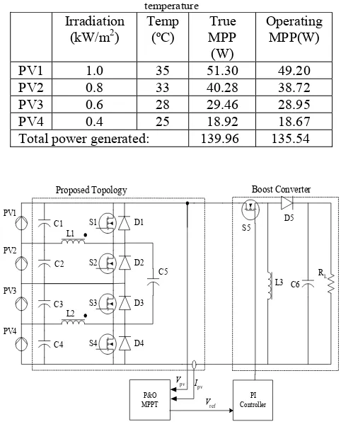
Fig. 1(a) shows a typical PVPS using a central inverter. For simplicity, a single string array with4 modules is depicted. Fig. 1(b) shows the proposed circuit. As can be seen, the bypass diode in Fig. 1(a) is removed. The basic idea of this topology is to transfer the power from non-shaded modules to the shaded modules until all modules in the string seem to have equal power level. Transferred energy is stored temporarily in capacitors C1−C4. This topology is divided into 2 groups. Group 1 consists of PV1 and PV2 together with their corresponding power electronics circuits, i.e. S1, D1, L1, C1, S2, D2 and C2. Group 2 includes PV3, PV4 with S3, S4, D3, D4, L2, C3 and C4. The transfer the power is from the PV with higher irradiance to the one which is shaded (within the same group). For example, when partial shading occurs on PV2, Group 1 is in operation; it transfers the unbalanced power from PV1 to PV2. Capacitor C5 is designed to balance the energy level between groups 1 and 2 when the total of irradiation of Group 1 and Group 2 is not equal. After equilibrium, all PV in the string will experience the same power level. As a result, maximum power is transferred even during partial shading is imposed on any of the modules. (b) The proposed topology
Figs. 2(a) and (b) detailed the operating stages of each group during partial shading. The operation of the circuit can be divided into two stages. During stage 1 (t0 < t < t1), S1 is
ON and S2 is OFF while for Group 2, S3 is ON and S4 is OFF. The current flows through S1, causing IL1 to increase
linearly due to constant voltage supply from PV1, V1. The same current flows in L2. Hence, energy is stored in L1 and
L2. The ripple current of the inductor during stage 1 is
PV1
Fig 2(a). Operation during stage 1, (b) Operation during stage 2. Consequently, the voltage across C5 can be written as
The charging and releasing energy process continue until all PVs and its capacitors have the same energy level. Therefore maximum power point can be achieved. The load current, Ipv is calculated as:
R
Note that, the analysis above is based on the assumption that PV2 and PV4 are shaded while PV1 and PV3 receive full irradiation. Similar analysis can be made for different shading configurations.
III. RESULT
A. Simulation
Fig. 3 shows the Matlab-Simulink simulation of the proposed topology with a boost converter as an interface converter. The implementation using boost converter and a
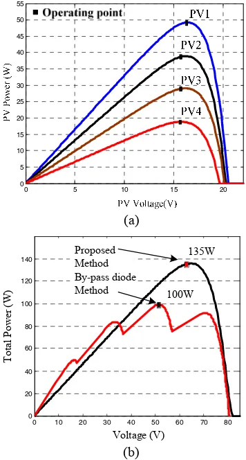
fixed resistive (instead of inverter and grid) is for simplicity. For MPPT, the normal perturbed and observed (P&O) scheme is used. A PI controller is applied to maintain the PV voltage, Vpv at the voltage reference, Vref. The latter is computed using the P&O MPPT algorithm. The BP-MSX60 PV model is used. To simulate the partial shading condition; each module is set to various irradiation patterns as shown in Table 1. Fig. 4(a) depicts the MPP operating point for each PV module under the irradiance of Table 1.
Fig. 4(b) shows the performance comparison between the proposed method and the bypass diodes topology. As can be clearly seen, using the proposed method, the system has recovered 35.54W or 25.4% more power than a system with the bypass diode.
TABLE 1: PV shading condition at different irradiation and temperature
Proposed Topology Boost Converter
S5
C6
Ipv
Fig 3: Simulation set-up to test the performance of proposed topology
B. Experimental
BYW29EX-200. A low cost 16-bit microcontroller was used to implement the P&O MPPT. For the micro-inverter, each module is equipped with a 100 W boost converter with P&O MPPT. To control the irradiance, a solar simulator using tungsten-halogen lamps is constructed.
0 5 10 15 20
0 5 10 15 20 25 30 35 40 45 50 55
(a)
0 10 20 30 40 50 60 70 80
0 20 40 60 80 100 120
140 Proposed
Method By-pass diode Method
Voltage (V)
T
o
ta
l P
o
w
er
(
W
) 100W
135W
(b)
Fig. 4 (a) PVs power curve and operation point of each PV modules. (b) Simulation result of the total generated output power
To perform the partial shading, all modules are first illuminated at 1.0 kW/m2. Then the irradiance of two modules, i.e. PV1 and PV2 is reduced to 0.14 kW/m2 and 0.30 kW/m2, respectively. Other modules are maintained at 1.0 kW/m2. Fig. 5 shows of response of the system when the above-mentioned shading is applied. Initially, when all the modules are fully illuminated, the total output power from the four modules at Standard Test Condition (STC) is 60×4=240W. However, the oscillogram in Fig. 5 (top trace) shows the power is measured at 203W. The reduction in power is probably due to the module operation at higher temperature, which causes the insolation to drop. At t=0, the partial shading is applied. Theoretically, using bypass the diode, the maximum achievable output power is 101.5W because the two shaded modules (PV1 and PV4) are bypassed. In this case only two modules are delivering
power; hence the 101.5 W. However, using the proposed circuit, the total output power is measured at 118W. This can be seen in Fig 5. The power recovered by using the proposed method is 16.5W, which is about 14% of the total output power. Note that, from previous section, the theoretical saving (using simulation) is approximately 25.4%. The difference is most probably due to the switches losses that are not considered during simulation.
PV Power (50W/Div) PV Voltage
(20V/Div)
PV Current (10V/Div) 203W
118W t=0
Fig. 5: PV transient response during shading that occurs at t=0. The irradiance of PV1 and PV2 is dropped from 1kW/m2 to 0.14kW/m2 and
1kW/m2 to 0.3kW/m2, respectively. The Irradiations for PV3 and PV4 are
unchanged at 1kW/m2
To investigate its efficiency performance, the proposed method is compared to two methods: (1) micro-inverter and (2) system using bypass diode. The efficiency is computed by taking the ratio of the output power to input power. Fig. 6 shows the histogram of the measured efficiency of the three topologies under the shading pattern shown in Table 2. For shading pattern 1, all modules are subjected to uniform irradiance, i.e. no partial shading condition is imposed. Shading pattern 2 has two modules at 50% shaded while the other two are fully irradiated. Shading pattern 3 and 4 are designed for three shaded modules, with the latter having its fourth module heavily shaded.
TABLE 2: PVs irradiation condition (kW/m2) at temperature range
(40-60)ºC
Condition PV1 PV2 PV3 PV4
1 0.70 0.70 0.70 0.70 2 1.00 0.50 1.00 0.50 3 1.00 0.86 0.60 0.40 4 1.00 0.86 0.60 0.20
clearly the case because the shaded modules are not delivering power at all.
On the other hand, the proposed method maintains high efficiency despite the occurrence of partial shading; hence it appears that the shading has little effect on its efficiency. The highest achievable efficiency is 97%.
For the micro-inverter, the efficiency is approximately constant for all shading conditions. This is to be expected because each module has its own inverter with MPPT controller and therefore it can harvest the energy even if the module is shaded. It efficiency value is slightly below the proposed method; most probably due to the higher losses for each individual inverter.
Fig. 6: Overall experimental efficiency comparison of different MPPT algorithm during partial shading condition show in Table 2
V. CONCLUSION
A simple circuit is proposed to increase the output power of PV system during partial shading. The idea is to recover the power from the shaded module, detour it to a power electronics circuit and process it to become part of the output power. Consequently, the inclusion of the proposed circuit enables the system to deliver more power compared to traditional bypass diode method. Simulation results show marked improvement in the output power, especially under heavy partial shading condition. The comparison is based on simulation done on bypass diode and micro-inverter. Experiment work has proved the excellent agreement with the simulation. An average efficiency 97% has been recorded for the proposed method. The extra power generated is expected to compensate for the cost of the extra components in the retrofit circuit and generates profit in the long run.
ACKNOWLEDGMENT
The authors would like to thank the Universiti Teknologi Malaysia and the Universiti Teknikal Malaysia Melaka for the facilities and equipment support. This research is funded by the ScienceFund Grant from the Ministry of Agriculture (MOA), Malaysia, under Vot Number 79411.
REFERENCES
[1] Myrzik, J.M.A.; Calais, M., "String and module integrated inverters for single-phase grid connected photovoltaic systems - a review," Power Tech Conference Proceedings, 2003 IEEE Bologna , vol.2, no., pp. 8 pp. Vol.2, 23-26 June 2003
[2] Miyatake, M.; Toriumi, F.; Endo, T.; Fujii, N.; , "A Novel maximum power point tracker controlling several converters connected to photovoltaic arrays with particle swarm optimization technique," Power Electronics and Applications, 2007 European Conference on , vol., no., pp.1-10, 2-5 Sept. 2007
[3] Ishaque, K., Salam, Z., Amjad, M., and Mekhilef, S. "An Improved Particle Swarm Optimization (PSO)-Based MPPT for PV With Reduced Steady-State Oscillation", IEEE Transactions on Power Electronics, vol. 27, pp. 3627-3638, 2012.
[4] Kurokawa, K.; Sugiyama, H.; Uchida, D.; Sakuta, K.; Sakamoto, K.; Ohshiro, T.; Matsuo, T.; Katagiri, T.; , "Extended performance analysis of 70 PV systems in Japanese field test program," Photovoltaic Specialists Conference, 1997., Conference Record of the Twenty-Sixth IEEE , vol., no., pp.1249-1252, 29 Sep-3 Oct 1997 [5] Di Piazza, M.C.; Pucci, M.; Ragusa, A.; Vitale, G.; , "Fuzzified PI
voltage control for boost converters in multi-string PV plants," Industrial Electronics, 2008. IECON 2008. 34th Annual Conference of IEEE , vol., no., pp.2338-2345, 10-13 Nov. 2008
[6] Kjaer, S.B.; Pedersen, J.K.; Blaabjerg, F.; , "A review of single-phase grid-connected inverters for photovoltaic modules," Industry Applications, IEEE Transactions on , vol.41, no.5, pp. 1292- 1306, Sept.-Oct. 2005.
[7] K. Ishaque, Z. Salam, H. Taheri, Syafaruddin, ‘Modeling and simulation of photovoltaic (PV) system during partial shading based on a two-diode model, Simulation Modelling Practice and Theory’, 19 (2011) 1613-1626.
[8] K. Ishaque, Z. Salam, H. Taheri, ‘Simple, fast and accurate two-diode model for photovoltaic modules’, Solar Energy Materials and Solar Cells, 95 (2011) 586-594.
[9] Maki, A.; Valkealahti, S.; , "Power Losses in Long String and Parallel-Connected Short Strings of Series-Parallel-Connected Silicon-Based Photovoltaic Modules Due to Partial Shading Conditions," Energy Conversion, IEEE Transactions on , vol.PP, no.99, pp.1-11,
60 65 70 75 80 85 90 95 100 105
1 2 3 4
Parti al Shading Pate rn
E
ff
ic
ie
n
c
y
(
%
)