An Optimized Switching Strategy for Quick
Dynamic Torque Control in
DTC-Hysteresis-Based Induction Machines
Auzani Jidin,
Student Member, IEEE
, Nik Rumzi Nik Idris,
Senior Member, IEEE
,
Abdul Halim Mohamed Yatim,
Senior Member, IEEE
, Tole Sutikno,
Student Member, IEEE
, and
Malik E. Elbuluk,
Senior Member, IEEE
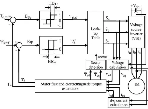
Abstract—A dynamic overmodulation strategy for fast dynamic torque control in direct torque control (DTC)-hysteresis-based in-duction machine is proposed. The fastest dynamic torque response with a six-step mode can be achieved in the proposed method by switching only the most optimized voltage vector that pro-duces the largest tangential component to the circular flux locus. This paper also discusses the performance of dynamic torque control in basic DTC in order to justify on how the proposed selected voltage vector results in excellent dynamic torque perfor-mance. The main benefit of the proposed method is its simplicity, since it only requires a minor modification to the conventional DTC-hysteresis-based structure and does not require a space vector modulator. To verify the feasibility of the proposed dy-namic overmodulation strategy, simulation and experimentation, as well as comparison with the conventional DTC scheme, are carried out. Results showed a significant improvement in the dy-namic torque response when compared to the conventional DTC-hysteresis-based method.
Index Terms—Direct torque control (DTC), dynamic over-modulation, hysteresis controller, induction machine, torque control.
I. INTRODUCTION
O
VER THE past years, direct torque control (DTC) scheme for induction motor drives has received enormous attention in industrial motor drive applications. The main rea-son for its popularity is due to its simple structure, particularly when compared with field-oriented control (FOC) scheme, which was introduced a decade earlier. Since DTC was firstManuscript received March 23, 2010; revised June 23, 2010 and August 7, 2010; accepted September 10, 2010. Date of publication October 14, 2010; date of current version July 13, 2011. This work was supported by the Ministry of Science, Technology and Innovation of the Malaysian Government.
A. Jidin is with the Department of Power Electronics and Drives, Faculty of Electrical Engineering, Universiti Teknikal Malaysia Melaka, Durian Tunggal 76100, Malaysia, and also with Universiti Teknologi Malaysia, Johor Bahru 81310, Malaysia (e-mail: [email protected]).
N. R. N. Idris and A. H. M. Yatim are with the Department of Energy Conversion, Faculty of Electrical Engineering, Universiti Teknologi Malaysia, Johor Bahru 81310, Malaysia (e-mail: [email protected]; [email protected]).
T. Sutikno is with the Department of Electrical Engineering, Faculty of In-dustrial Technology, Universitas Ahmad Dahlan, Yogyakarta 55164, Indonesia, and also with Universiti Teknologi Malaysia, Johor Bahru 81310, Malaysia (e-mail: [email protected]).
M. E. Elbuluk is with the Department of Electrical and Computer Engineer-ing, University of Akron, Akron, OH 44325-3904 USA (e-mail: melbuluk@ uakron.edu).
Color versions of one or more of the figures in this paper are available online at http://ieeexplore.ieee.org.
Digital Object Identifier 10.1109/TIE.2010.2087299
introduced, several variations to its original structure (which we referred to as DTC hysteresis based) [1] were proposed to overcome the inherent disadvantages in any hysteresis-based controller, such as variable switching frequency, high sampling requirement for digital implementation, and high torque ripple [2]–[11]. Recently, predictive control strategy has found appli-cations in motor drives [12]–[21]. Predictive control applied to DTC has gain considerable amount of attention, particularly due to its ability to reduce the torque ripple, as well as the switching frequency [8]–[10], [21]. In particular, model pre-dictive control (MPC), which was applied in [8] and [9], uses hysteresis comparators but with the switching table replaced with online optimization algorithm. However, the application of MPC during a large step change in torque demand will result in significant computational burden, whereas as will be shown later in this paper, a simplified method can be used. Furthermore, the use of MPC during the large step change in torque command does not guarantee the fastest torque response. The most popular variation of DTC of induction motor drives is the one that is based on space vector modulation (SVM), which normally referred to as DTC-SVM [22]–[31]. The major difference between DTC-hysteresis-based induction motor and DTC-SVM is the way the stator voltage is generated. In DTC-hysteresis-based induction motor, the applied stator voltage depends on voltage vectors, which are selected from a lookup table. The selections are based on the requirement of the torque and flux demands obtained from the hysteresis comparators. On the other hand, in DTC-SVM, a stator voltage reference is calculated or generated within a sampling period, which is then synthesized using the space vector modulator. The stator voltage reference vector is calculated based on the requirement of torque and flux demands. Due to the regular sampling in SVM, the DTC-SVM produces constant switching frequency, as opposed to the variable switching frequency in hysteresis-based DTC, however, at the expense of more complex implementation. Various methods to estimate the voltage reference vector had been reported; these include the use of proportional–integral current controller [23], stator flux vector error [24], [25], proportional–integral torque and flux controllers [26]–[28], and predictive and deadbeat controllers [29]–[31]. During the large torque demand, it is inevitable that this reference exceeds the voltage vector limits enclosed by the hexagonal boundary. Under this condition, the SVM has
to be operated in what is termed as dynamic overmodulation mode. The voltage reference vector has to be modified such that it will lie on the hexagonal boundary. Several methods [29], [30], [32], [33] have been proposed, and to some extent, these methods have managed to minimize the voltage vector error, as well as obtained a fast torque response; however, the majority of them do not guarantee the fastest torque re-sponse.
In hysteresis-based DTC, during the large torque demand, the torque hysteresis comparator will give an output that demands the selection of voltage vector to increase the torque. At the same time, a flux hysteresis comparator will regulate the flux to achieve a circular flux path. This circular flux path, however, does not correspond to the fastest torque demand. In other words, the basic method that is used to select the voltage vectors in hysteresis-based DTC will not guarantee the fastest torque response. A minor modification to the voltage vector selection needs to be performed to ensure the fastest torque response during this condition.
In this paper, a simple DTC-hysteresis-based induction ma-chine with fastest dynamic torque response is presented. The voltage vector used in this proposed dynamic overmodulation is similar with that proposed in [31] and [34]; however, in [31], Tripathiet al.use a DTC-SVM with complex predictive stator flux control structure, while in [34], the stator current contains lower harmonic contents at any operating condition due to the hexagonal shape of the stator flux locus. In this paper, the optimized voltage vector to produce fast dynamic response that corresponds to the voltage vector that produces the largest tangential flux component is selected. The selec-tion of the optimized voltage vector can be simply done by modifying the flux error status before it is being fed to the lookup table. In this way, the fastest dynamic torque control with six-step operation is achieved, and the simple structure of DTC-hysteresis-based induction machine is retained without the need of SVM. In Section II of this paper, the basic principle of DTC is briefly discussed. Section III discusses the previous proposed methods of dynamic overmodulation. The dynamic overmodulation operation in basic DTC-hysteresis-based in-duction machine and the proposed dynamic overmodulation method for DTC-hysteresis-based induction machine are also discussed. Section IV presents the simulation and experimental results of the proposed method. Finally, conclusion is given in Section V.
II. PRINCIPLE OFDTC
The behavior of induction machine in DTC drives can be described in terms of space vectors by the following equations written in stator stationary reference frame:
vs =rsis+
Fig. 1. Structure of basic DTC-hysteresis-based induction machine.
where P is the number of pole pairs; ωr is the rotor electric angular speed in radians per second; Ls, Lr, and Lm are the motor inductances; and δ is the angle between the stator flux linkage and stator current space vectors. Based on (1), theds- andqs-axis stator fluxes in a stationary reference frame can be written as or one), the voltage vectors in (6) are given by
vs,ds =
The electromagnetic torque given in (5) can be rewritten in ds–qscoordinates as
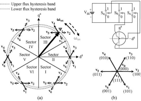
Fig. 2. Selection of the optimum inverter output voltage vectors. (a) Each sector indicates the appropriate voltage vectors. (b) Eight possible switch configurations in the three-phase voltage source inverter.
vectors are required. On the other hand, to control the torque, one active voltage vector is used to increase the torque, while a zero voltage vector is used to reduce it. By limiting the torque and flux errors within their hysteresis bands, a decoupled control of torque and flux is achieved.
III. DYNAMICTORQUECONTROL
In practice, a fast dynamic torque control can be achieved by fully utilizing a dc bus voltage through an overmodulation strategy. The switching strategy to perform overmodulation mode during torque transient condition is usually referred to as dynamic overmodulation. In DTC-SVM, dynamic overmodula-tion occurs whenever there is a large torque demand such that the generated voltage reference vector exceeds the hexagonal boundary on a voltage vector plane. In hysteresis-based DTC, there is no voltage reference vector involved. However, an equivalent condition occurs whenever the hysteresis torque comparator produces a demand to continuously increase the torque. At the same time, the flux is regulated to follow the circular path using two active voltage vectors.
A. Previous Methods Used for Dynamic Overmodulation
It had been reported that the overmodulation strategy is commonly utilized in SVM approach [23], [29]–[31], [35], [36]. For advanced motor control, the use of SVM is preferable than the other techniques (for example, Havaet al. [37] and Kerkmanet al.[38] use triangular carrier based) since it is more flexible (uses only a single reference voltage as the input modu-lator) and able to exploit the overmodulation region to six-step mode [23], [31], [36]. However, the motor control performance using SVM is dependent on the accuracy of the estimation of the reference voltage. Moreover, the computations of reference voltage and maximum possible voltage used for the imple-mentation of dynamic overmodulation lead to more complex control structures. Several methods of dynamic overmodulation are reported. Fig. 3 shows the comparison of some modified voltage referencesv
[i] (e.g., wheni= 1, proposed in [1]) with
respect to the original voltage reference vector vs,ref, which is beyond the hexagonal boundary of the voltage vectors. Note that the voltage vector components are not drawn to scale. It can be seen that (from Fig. 1) [31] and [34] switched only a single voltage vector which isvk+2during dynamic overmodulation.
This single selection of vector shows the occurrence of a six-step operation that produces the fastest dynamic torque control, as will be discussed later in this paper. On the other hand, the other methods result in slower dynamic torque response since two active states are alternately switched during the dynamic condition. For example, [29] Habetleret al.used two active states utilizing deadbeat control in order to maintain the magnitude of stator flux under control for any condition.
Later, [30] was proposed to simplify the complexity control structure in [29] (where it does not provide a deadbeat control of the magnitude flux as a transient torque is encountered), and hence, it results in a faster dynamic torque control. In this way, the modified voltage vectorv[30] has the same angleγas the original reference voltagevs,refbut with a modified magnitude.
In [32], the reference voltage vs,ref was modified tov[32] such that the error between the magnitudes ofv[32]andvs,ref
is minimized. This means that the modified voltage vectorv[32] should be closest to the original reference vector vs,ref by
ensuring that the line joiningvs,ref andv[32] is orthogonal to the hexagon boundary.
Although the SVM technique has been widely used in many advanced DTC and FOC of motor drives, it actually compli-cates the original control and structure of the drive system. This is due to the fact that more computations involving the estimation ofvs,refand the approximation of the modified volt-age reference are required, as mentioned earlier. The simplicity advantage of DTC-hysteresis-based structure is lost.
B. Dynamic Torque Control in Basic Hysteresis-Based DTC
It is well known that the original DTC scheme proposed by Takahashi and Naguchi [1] offers fast instantaneous torque and flux control due to the optimized voltage vector selection in controlling simultaneously both flux and torque. During large torque demand, and, hence, large torque error, the hysteresis torque comparator produces a single status that requires an increase in torque. This means that, under this condition, no zero vectors are selected to reduce the torque. At the same time, the flux hysteresis will regulate the flux to follow the circular path using two active voltage vectors. This is similar to a condition in DTC-SVM in which the stator voltage reference vector follows the hexagonal boundary in the overmodulation mode, which is the reference voltage v[29] in Fig. 3. Since no zero voltage vectors are applied, rapid changes in the flux vector position and, hence, a quick dynamic torque response are achieved. However, this method does not give the fastest dynamic torque response simply because two active voltage vectors are switched during the dynamic condition. In order to achieve the fastest dynamic torque response, only a single vector should be switched and held instead of two active voltage vectors.
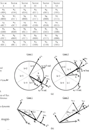
TABLE I
LOOKUPTABLE(VOLTAGEVECTORSELECTION)
Fig. 3. Variations of the proposed voltage vectors applied during the dynamic overmodulation mode.
will be expressed in terms of the stator and rotor flux magni-tudes, as given in the following:
Te=
3 2P
Lm σLsLr
ΨsΨrsinδsr (9)
whereσis the total leakage factor andδsris the angle difference between the stator and rotor flux vectors and plays a vital role in controlling the output torque. The relationship between the rotor and stator flux vectors in the rotor flux reference frame can be written as
Ψrr= Lm/Ls
1 +pστr
Ψrs (10)
whereτris the rotor time constant. If the ohmic drop in (1) is neglected, then we can approximate the change in stator flux as
∆Ψs =vs∆t. (11)
Equation (11) indicates that an instantaneous angular velocity of the stator flux is irregular due to the switching voltage vectors. According to (10), the rotor flux will follow the stator flux, however with the irregular motion removed due to the low-pass-filtering action.
Fig. 4. Effects of selecting different switchings under dynamic condition. (a) Stator voltage vector in stator flux. (b) Comparison of the load anglesδsr generated by the same magnitude of appropriate voltage vectors.
Fig. 4 shows the space vectors of the stator and rotor flux linkages moving in the counterclockwise direction. The motion of the stator flux is dictated by the voltage vectorsvk+1 and vk+2. Case 1 is when the stator flux is about to enter sectork (atαk = 0rad), while case 2 is when the stator flux is about to leave sectork(atαk=π/3rad). The dynamic torque response can be studied by looking at the effects of applying the possible two voltage vectors on the angle ∆δsr. For this purpose, the vectors are redrawn as shown in Fig. 4(b). From Fig. 4(a) and (b), it can be seen thatvk+1has a larger tangential component
to the circular flux locus, while the component of vk+2 has
a larger radial (negative) component in case 1. On the other hand,vk+1has a larger radial component, while vk+2 has a
Fig. 5. Structure of DTC-hysteresis-based induction machine with the pro-posed modification of flux error status block.
compared to the irregular rotation of stator flux, it can be seen that ∆δsr,1 is larger when vk+1 is switched for case 1, and
on the other hand,∆δsr,2is larger whenvk+2is switched for
case 2. In fact, if the sector is subdivided into subsectors (i) and (ii) based on (12), vectorvk+1will result in a larger∆δsr throughout subsector (i), and vk+2 will give a larger ∆δsr throughout subsector (ii)
0≤αk< π/6rad, for subsector i
π/6≤αk< π/3rad, for subsector ii. (12)
According to (9), with a larger∆δsr,vk+1andvk+2 will
give a faster dynamic torque response in subsectors (i) and (ii), respectively.
C. Proposed Dynamic Torque Control
In the proposed dynamic overmodulation method, the most optimized voltage vector that produces the largest tangential to the circular flux locus is switched and held (instead of selecting two active voltage vectors) during torque dynamic to achieve the fastest dynamic torque control. As discussed in the previous section, if sector kis considered, this would be vector vk+1
in subsector (i) and vectorvk+2in subsector (ii). Fig. 5 shows the structure of DTC-hysteresis-based induction machine with the proposed modification of flux error status. Notice that all components of the DTC-hysteresis-based scheme are retained, except for the inclusion of the “modification of flux error status” block which is responsible to perform the dynamic overmodulation mode. The selection of the optimized voltage vector to give the fastest torque response can be simply done by modifying the flux error status(Ψ+)to a new flux status(Ψ−) before it is being fed to the lookup table. The “modification of flux error status” block, and, hence, the proposed dynamic over-modulation, is activated when the torque errorETe is greater than twice of the hysteresis band of torque controllerHBTe.
When the “modification of flux error status” block is acti-vated, the output of this block Ψ−
s depends on the position of the flux position within a sector, as shown in Fig. 6. If it
Fig. 6. Proposed digital outputs in modified flux error status correspond to the optimized voltage vectors for every subsector in each sector.
TABLE II
DTC-HYSTERESIS-BASEDSYSTEM AND
INDUCTIONMACHINEPARAMETERS
is in subsector (i) Ψ−
s = 0, hence vk+1 is selected, and if it
is in subsector (ii) Ψ−
s = 1, vk+2 is selected. The border of
the sectors and subsectors can be easily calculated using the threshold values of Ψs
s,q, denoted asΨsq,1 and Ψsq,2, which can be calculated as
Ψsq,1= Ψss,dtan(π/6) (13)
Ψsq,2= Ψss,dtan(π/3). (14)
IV. SIMULATION ANDEXPERIMENTALRESULTS
Fig. 7. Complete drive system (a) photograph of the experimental setup and (b) functional block diagram of the experimental setup.
an insulated-gate bipolar transistor inverter and a 1.5-kW four-pole squirrel-cage induction motor. The DTC-hysteresis-based system and induction machine parameters are the same to the parameters used for the simulation. For safety reason, the dc voltage was limited to 240 V, which means that the based speed is reduced to 570 r/min. It should be noted that using a higher dc voltage would further enhance the torque response since the higher dc voltage will result in a higher rate of change of torque. The control algorithm is implemented on a DSPACE 1102 and Altera field-programmable gate array (APEX20KE). The sampling period of the DTC scheme, including the proposed dynamic overmodulation, is 55µs.
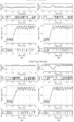
Some tests have been carried out to compare the perfor-mances of dynamic torque control in the basic hysteresis-based DTC with and without the proposed dynamic overmodulation. For the sake of identification, the DTC without the proposed overmodulation is referred as DTC1, while the one with the pro-posed dynamic overmodulation strategy is referred as DTC2. The dynamic torque control is performed by applying a step change of torque reference from 1.5 to 9.0 N·m at two different stator flux positions. Based onΨs
d andΨ s
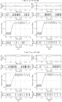
q, a step change in the torque reference is introduced atαk =π/24rad [subsector (i) within sector 2] and atαk=π/6 rad [subsector (ii) within sector 2]. To make the comparisons fair, the dynamic torque controls in both DTC schemes were performed under the same load torque conditions so that the rotor speed operated at around 410 r/min.
The simulation and experimental results under these two conditions are shown in Figs. 8 and 9, respectively. It can be seen that, for DTC1, two active voltage vectors are se-lected during the torque dynamic; this is indicated by the flux error status waveform which switches between one and zero. For the proposed overmodulation (DTC2), the single flux error status is held; hence, only a single vector is se-lected during the torque dynamic. The sese-lected voltage vec-tor, as discussed in the previous section, provides the fastest torque response. The effect of the proposed overmodulation on the stator flux locus for the two different stator flux
Fig. 9. Comparison by experimental of dynamic torque performances be-tween (a) DTC1 and (b) DTC2, when a dynamic torque control occurs as the stator flux position atαk=π/24rad orαk=π/6rad (at the middle of sector 2).
Fig. 10. Comparison of stator flux loci obtained in (a) DTC1 and (b) DTC2 (for one complete flux wave cycle), when a dynamic torque condition occurs at αk=π/24rad.
positions can be seen from the experimental results, as shown in Figs. 10 and 11.
The shape and, hence, the magnitude of the stator flux are affected since the single voltage vector is switched during the
Fig. 11. Comparison of stator flux loci obtained in (a) DTC1 and (b) DTC2 (for one complete flux wave cycle), when a dynamic torque condition occurs at αk=π/6rad.
dynamic overmodulation. When the torque dynamic occurs in subsector (i), the single voltage vector that produces the fastest torque response is selected. This vector also increases the flux, causing the flux locus to deviate from the circular locus momentarily, as shown in Fig. 10. On the other hand, when the torque dynamic occurs in subsector (ii), a single voltage vector that gives the fastest torque response and at the same time reduces the flux is selected. This is indicated by the stator flux locus shown in Fig. 11. For both cases, the deviation in the flux locus from the circular locus occurs momentarily during the torque dynamic.
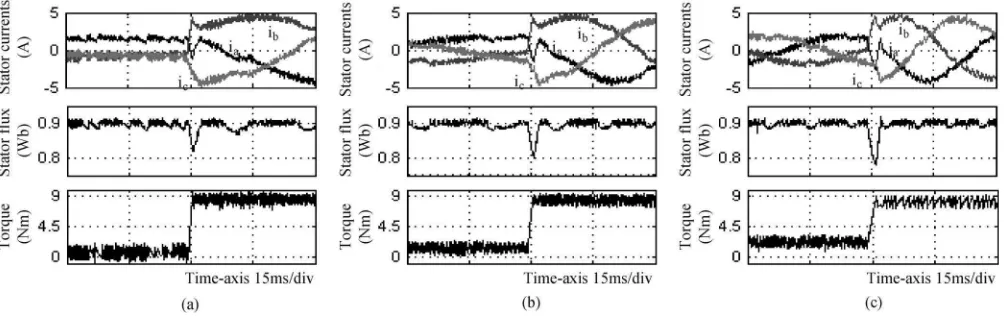
It is quite interesting to observe the behavior of motor currents as the flux magnitude is suddenly distorted due to the proposed switching strategy during the torque dynamic condition. Figs. 12 and 13 show the behavior of motor currents for DTC2 at three different operating speeds, named as Speed 1 (at 100 r/min), Speed 2 (at 300 r/min), and Speed 3 (at 550 r/min). These speeds represent the “low,” “medium,” and “high” speed ranges, respectively, relative to the reduced based speed of 570 r/min. For each operating speed, a step change of reference torque is applied at αk=π/24 rad and αk= π/6 rad. As can be seen from the figures, the three-phase stator currents show rapid change during the torque dynamic, which occurs in a relatively very short period particularly for Speed 1. Thus, the possibility of facing an overcurrent problem is not serious, as the sharp increases of currents occur within a very short period of time. It can also be noticed that (in Figs. 12 and 13) the performance of dynamic torque control decreases (i.e., produces slower torque response) as the motor speed op-eration increases. This is due to the fact that the rate of change of torque depends on the operating conditions (i.e., dc voltage, load torque, and speed), which has been discussed in [39] and [40]. Nevertheless, regardless of the speed of operation, the torque response with the proposed dynamic overmodulation would give faster torque response when compared with the conventional DTC that uses two voltage vectors during the torque dynamic.
V. CONCLUSION
Fig. 12. Behavior of motor currents when the flux magnitude suddenly increases due to the proposed switching strategy, as the dynamic torque occurs at αk=π/24rad. The dynamic torque control is applied at three different speed operations for (a) Speed 1 at 100 r/min, (b) Speed 2 at 300 r/min, and (c) Speed 3 at 550 r/min.
Fig. 13. Behavior of motor currents when the flux magnitude suddenly increases due to the proposed switching strategy, as the dynamic torque occurs at αk=π/6rad. The dynamic torque control is applied at three different speed operations for (a) Speed 1 at 100 r/min, (b) Speed 2 at 300 r/min, and (c) Speed 3 at 550 r/min.
produces the largest tangential to the circular flux locus is switched and held so that a fast rate of change of angle∆δsr is achieved. The selection of the optimized voltage vector is simply obtained by modifying the flux error status before it is being fed to the lookup table. The main benefit of the proposed method is its simplicity and, at the same time, be able to produce the fastest dynamic torque response with a six-step mode. The dynamic overmodulation is achieved without the need of space vector modulator.
REFERENCES
[1] I. Takahashi and T. Naguchi, “A new quick-response and high-efficiency control strategy of an induction motor,”IEEE Trans. Ind. Appl., vol. IA-22, no. 5, pp. 820–827, Sep. 1986.
[2] Y. S. Lai and J. H. Chen, “A new approach to direct torque control of induction motor drives for constant inverter switching frequency and torque ripple reduction,”IEEE Trans. Energy Convers., vol. 16, no. 3, pp. 220–227, Sep. 2001.
[3] L. Romeral, A. Arias, E. Aldabas, and M. G. Jayne, “Novel direct torque control (DTC) scheme with fuzzy adaptive torque-ripple reduction,”IEEE Trans. Ind. Electron., vol. 50, no. 3, pp. 487–492, Jun. 2003.
[4] N. R. N. Idris and A. H. M. Yatim, “Direct torque control of induction machines with constant switching frequency and reduced torque ripple,”
IEEE Trans. Ind. Electron., vol. 51, no. 4, pp. 758–767, Aug. 2004.
[5] V. Ambrozic, G. S. Buja, and R. Menis, “Band-constrained technique for direct torque control of induction motor,”IEEE Trans. Ind. Electron., vol. 51, no. 4, pp. 776–784, Aug. 2004.
[6] C. Lascu, I. Boldea, and F. Blaabjerg, “Variable-structure direct torque control—A class of fast and robust controllers for induction machine drives,” IEEE Trans. Ind. Electron., vol. 51, no. 4, pp. 785–792, Aug. 2004.
[7] C. Lascu and A. M. Trzynadlowski, “A sensorless hybrid DTC drive for high-volume low-cost applications,”IEEE Trans. Ind. Electron., vol. 51, no. 5, pp. 1048–1055, Oct. 2004.
[8] T. Geyer, G. Papafotiou, and M. Morari, “Model predictive direct torque control—Part I: Concept, algorithm, and analysis,” IEEE Trans. Ind. Electron., vol. 56, no. 6, pp. 1894–1905, Jun. 2009.
[9] G. Papafotiou, J. Kley, K. G. Papadopoulos, P. Bohren, and M. Morari, “Model predictive direct torque control—Part II: Implementation and experimental evaluation,” IEEE Trans. Ind. Electron., vol. 56, no. 6, pp. 1906–1915, Jun. 2009.
[10] J. Beerten, J. Verveckken, and J. Driesen, “Predictive direct torque control for flux and torque ripple reduction,”IEEE Trans. Ind. Electron., vol. 57, no. 1, pp. 404–412, Jan. 2010.
[11] K. Shyu, J. Lin, V. Pham, T. Wang, and M. Yang, “Global minimum torque ripple design for direct torque control of induction motor drives,”IEEE Trans. Ind. Electron., vol. 57, no. 9, pp. 3148–4156, Sep. 2010. [12] M. Cirrincione and M. Pucci, “An MRAS-based sensorless
high-performance induction motor drive with a predictive adaptive model,”
IEEE Trans. Ind. Electron., vol. 52, no. 2, pp. 532–551, Apr. 2005. [13] P. Correa, M. Pacas, and J. Rodriguez, “Predictive torque control for
[14] R. Morales-Caporal and M. Pacas, “A predictive torque control for the synchronous reluctance machine taking into account the magnetic cross saturation,”IEEE Trans. Ind. Electron., vol. 54, no. 2, pp. 1161–1167, Apr. 2007.
[15] M. Nemec, D. Nedeljkovic, and V. Ambrozic, “Predictive torque control of induction machines using immediate flux control,”IEEE Trans. Ind. Electron., vol. 54, no. 4, pp. 2009–2017, Aug. 2007.
[16] H. Miranda, P. Cortes, J. I. Yuz, and J. Rodriguez, “Predictive torque control of induction machines based on state-space models,”IEEE Trans. Ind. Electron., vol. 56, no. 6, pp. 1916–1924, Jun. 2009.
[17] S. Bolognani, L. Peretti, and M. Zigliotto, “Design and implementation of model predictive control for electrical motor drives,”IEEE Trans. Ind. Electron., vol. 56, no. 6, pp. 1925–1936, Jun. 2009.
[18] F. Barrero, M. R. Arahal, R. Gregor, S. Toral, and M. J. Duran, “A proof of concept study of predictive current control for VSI-driven asymmetrical dual three-phase ac machines,”IEEE Trans. Ind. Electron., vol. 56, no. 6, pp. 1937–1954, Jun. 2009.
[19] F. Barrero, M. R. Arahal, R. Gregor, S. Toral, and M. J. Duran, “One-step modulation predictive current control method for the asymmetrical dual three-phase induction machine,”IEEE Trans. Ind. Electron., vol. 56, no. 6, pp. 1974–1983, Jun. 2009.
[20] F. Morel, X. Lin-Shi, J.-M. Retif, B. Allard, and C. Buttay, “A compara-tive study of prediccompara-tive current control schemes for a permanent-magnet synchronous machine drive,”IEEE Trans. Ind. Electron., vol. 56, no. 7, pp. 2715–2728, Jul. 2009.
[21] M. Pacas and J. Weber, “Predictive direct torque control for the PM synchronous machine,” IEEE Trans. Ind. Electron., vol. 52, no. 5, pp. 1350–1356, Oct. 2005.
[22] G. Foo and M. F. Rahman, “Sensorless direct torque and flux-controlled IPM synchronous motor drive at very low speed without signal injection,”
IEEE Trans. Ind. Electron., vol. 57, no. 1, pp. 395–403, Jan. 2010. [23] A. M. Khambadkone and J. Holtz, “Compensated synchronous PI current
controller in overmodulation range and six-step operation of space-vector-modulation-based vector-controlled drives,”IEEE Trans. Ind. Electron., vol. 49, no. 3, pp. 574–580, Jun. 2002.
[24] M. Fu and L. Xu, “A sensorless direct torque control technique for perma-nent magnet synchronous motors,” inConf. Rec. IEEE IAS Annu. Meeting, 1999, vol. 1, pp. 159–164.
[25] D. Casadei, G. Serra, A. Tani, L. Zarri, and F. Profumo, “Performance analysis of a speed-sensorless induction motor drive based on a constant-switching-frequency DTC scheme,”IEEE Trans. Ind. Appl., vol. 39, no. 2, pp. 476–484, Mar./Apr. 2003.
[26] Y. Xue, X. Xu, T. G. Habetler, and D. M. Divan, “A low cost stator flux oriented source variable speed drive,” inConf. Rec. IEEE IAS Annu. Meeting, 1990, vol. 1, pp. 410–415.
[27] C. Lascu, I. Boldea, and F. Blaabjerg, “A modified direct torque control for induction motor sensorless drive,”IEEE Trans. Ind. Appl., vol. 36, no. 1, pp. 122–130, Feb. 2000.
[28] F. Hoffmann and M. Janecke, “Fast torque control of an IGBT-inverter fed three-phase A.C. drive in the whole speed range—Experimental re-sults,” inProc. 6th Eur. Power Electron. Conf., Sevilla, Spain, 1995, pp. 3.399–3.404.
[29] T. Habetler, F. Profumo, M. Pastorelli, and L. Tolbert, “Direct torque con-trol of induction machines using space vector modulation,”IEEE Trans. Ind. Appl., vol. 28, no. 5, pp. 1045–1053, Sep./Oct. 1992.
[30] T. G. Habetler, F. Profumo, and G. Griva, “Performance evaluation of a direct torque controlled drive in the continuous PWM-square wave transition region,”IEEE Trans. Power Electron., vol. 10, no. 4, pp. 464– 471, Jul. 1995.
[31] A. Tripathi, A. M. Khambadkone, and S. K. Panda, “Dynamic control of torque in overmodulation and in the field weakening region,”IEEE Trans. Power Electron., vol. 21, no. 4, pp. 1091–1098, Jul. 2006.
[32] H. Mochikawa, T. Hirose, and T. Umemoto, “Overmodulation of voltage source PWM inverter,” inProc. JIEE Int. Soc. Conf., 1991, pp. 466–471. [33] S. Jul-Ki and S. K. Sul, “A new overmodulation strategy for induction
mo-tor drive using space vecmo-tor PWM,” inProc. IEEE Appl. Power Electron. Conf., Mar. 1995, pp. 211–216.
[34] M. Depenbrock, “Direct self control of inverter-fed of induction ma-chine,” IEEE Trans. Power Electron., vol. 3, no. 4, pp. 420–429, Oct. 1988.
[35] D. W. Chung and S. K. Sul, “A new dynamic overmodulation strategy for high performance torque control of induction motor drives,” inProc. 14th APEC, 1999, vol. 1, pp. 264–270.
[36] J. Holtz, W. Lotzkat, and A. Khambadkone, “On continuous control of PWM inverters in the overmodulation range including the six-step mode,” IEEE Trans. Power Electron., vol. 8, no. 5, pp. 546–553, Oct. 1993.
[37] A. M. Hava, S.-K. Sul, R. J. Kerkman, and T. A. Lipo, “Dynamic over-modulation characteristics of triangle intersection PWM methods,”IEEE Trans. Ind. Appl., vol. 35, no. 4, pp. 896–907, Jul./Aug. 1999.
[38] R. J. Kerkman, T. M. Rowan, D. Leggate, and B. J. Seibel, “Control of PWM voltage inverters in pulse dropping range,”IEEE Ind. Appl. Mag., vol. 2, no. 5, pp. 24–31, Sep./Oct. 1996.
[39] D. Casadei, G. Serra, and A. Tani, “Analytical investigation of torque and flux ripple in DTC schemes for induction motors,” inProc. IEEE IECON, New Orleans, LA, 1997, pp. 552–556.
[40] J. W. Kang and S. K. Sul, “Analysis and prediction of inverter switching frequency in direct torque control of induction machine based on hystere-sis bands and machine parameters,”IEEE Trans. Ind. Electron., vol. 48, no. 3, pp. 545–553, Jun. 2001.
Auzani Jidin(S’09) received the B.Eng. and M.Eng. degrees in power electronics and drives from Univer-siti Teknologi Malaysia, Johor Bahru, Malaysia, in 2002 and 2004, respectively, where he is currently working toward the Ph.D. degree.
He is currently a Lecturer with the Department of Power Electronics and Drives, Faculty of Electrical Engineering, Universiti Teknikal Malaysia Melaka, Durian Tunggal, Malaysia. His research interests include the field of power electronics, motor drive systems, field-programmable gate array, and DSP applications.
Nik Rumzi Nik Idris(M’97–SM’03) received the B.Eng. degree in electrical engineering from the University of Wollongong, Wollongong, Australia, in 1989, the M.Sc. degree in power electronics from Bradford University, Bradford, U.K., in 1993, and the Ph.D. degree from Universiti Teknologi Malaysia (UTM), Johor Bahru, Malaysia, in 2000.
He is currently an Associate Professor with UTM. His research interests include ac drive systems and DSP applications in power electronic systems.
Dr. Idris is an Administrative Committee Member of the Industry Applications Societies/Power Electronics/Industrial Electronics Joint Chapter of IEEE Malaysia Section.
Abdul Halim Mohamed Yatim (M’89–SM’01) received the B.Sc. degree in electrical and elec-tronic engineering from Portsmouth Polytechnic, Portsmouth, U.K., in 1981 and the M.Sc. and Ph.D. degrees in power electronics from Bradford Univer-sity, Bradford, U.K., in 1984 and 1990, respectively. He is currently a Professor with Universiti Teknologi Malaysia, Johor Bahru, Malaysia, where he is the Dean of the Faculty of Electrical Engineering.
Tole Sutikno(S’08) received the B.Eng. degree in electrical engineering from Diponegoro University, Semarang, Indonesia, in 1999 and the M.Eng. de-gree in electrical engineering from Gadjah Mada University, Jakarta, Indonesia, in 2004. He is cur-rently working toward the Ph.D. degree at Universiti Teknologi Malaysia, Johor Bahru, Malaysia.
Since 2001, he has been a Lecturer with the Department of Electrical Engineering, Faculty of Industrial Technology, Universitas Ahmad Dahlan, Yogyakarta, Indonesia. His research interests include the field of power electronics, motor drive systems, and field-programmable gate array applications.
Malik E. Elbuluk(S’79–M’79–SM’97) received the B.Sc. (with honors) degree in electrical engineering from the University of Khartoum, Khartoum, Sudan, in 1976 and the M.S., E.E., and D.Sc. degrees in elec-trical engineering from the Massachusetts Institute of Technology, Cambridge, in 1980, 1981, and 1986, respectively.
Since 1989, he has been with the University of Akron, Akron, OH, where he is currently a Profes-sor. His teaching and research interests include the areas of power electronics, electric machines, control systems, fuzzy logic, and neural networks.