Development of Vehicle Blind Spot System for Passenger Car
MUHAMMAD ZAHIR Hassan
1, aand HAZIQ IRFAN Zainal Ariffin
1, b1
Green Technology Vehicle Research Group, Center of Advanced Research on Energy (CARE), Faculty of Mechanical Engineering, Universiti Teknikal Malaysia Melaka, Hang Tuah Jaya, 76100
Durian Tunggal, Melaka, Malaysia
a
[email protected], [email protected]
Keywords: blind spot system, sensor.
Abstract. Blind spot of a passenger car is an area around the vehicle that cannot be seen while looking either forward or through side or rear view mirror. In this paper, a blind spot system known as ZRT Vehicle Blind Spot System (ZRT-VBSS) has been developed using Arduino and ultrasonic sensors to overcome the problem. The system is capable to detect a moving vehicle in blind spot area under three main condition of which static, dynamic speed operation at 60 and 100 km/h and also overtake position. The results from the experimental investigation show that ZRT-VBSS is capable to perform at various operating condition that make it reliable to provide solution for driver to overcome the blind spot phenomenon.
Introduction
Vehicle blind spot area depends on two main factors that is the height of the driver and the vehicle size. As an average height of Malaysian drivers for men is 1.67m, and 1.53m for women, it is importance to have a blind spot detection system that cater for the Malaysian market. This is very important as for driver with the height below 1.6 meters; the blind spot area is subjected to increase. The size of the average Sedan car also contributes to blind spot area as the length of the car range from 5 up to 9 meters. [1]
Vehicle Blind Spot System is a system that is build to alert the driver if there is any potential collision object within the blind spot area [2]. The system comes with a microcontroller board and sensors. The data that are collected from the sensors will determine whether the object is a high risk potential object or not. The sensors play a very important part in the system as the sensors need to detect and send data to the microprocessor. The microprocessor also requires to have a high processing speed so the data can be process in real time. Without the real time processing data capability, then the data cannot be counted as reliable.
Development of the ZRT-VBSS System
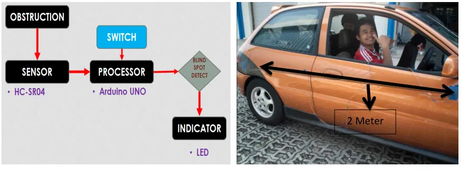
ZRT-VBSS as shown in Figure 1 consist of two sensors that interact with a microprocessor and LED alarm. ZRT-VBSS define the high risk potential object when the object moves at speed less than 28.8 km/h to the relative speed of the driver’s vehicle. The system uses an ultrasonic 4-pin HC-SR04 which is connected to the Arduino UNO microprocessor. The ultrasonic sensor work by sending short ultrasonic pulse transmitted at time zero, indicated by the moving object. Detector receives this signal and converts it into electrical signals. Next, the pulse spread when a fading echo. This period is called the period of the cycle. If the pulse width of 10µs trigger signal is sent to the pin, Ultrasonic module will deliver the output of eight 40 kHz ultrasonic signal and detect the echo back. The LED is then connected to the microprocessor as an alarm to warn the driver. The sensors, microprocessor and the alarm can send, receive and process the data in real time. A switch at the signal is also added to remove any false alarm. If the signal has been triggered than the system alarm will work promptly.
Applied Mechanics and Materials Vol. 393 (2013) pp 350-353 © (2013) Trans Tech Publications, Switzerland
doi:10.4028/www.scientific.net/AMM.393.350
Fig. 1: ZRT-VBSS flow chart Fig. 2: Sonar sensor placement distance
The sensor is then mounted at the side mirror and at the back side of the car. The distance of two sensors needs to be approximately 2 meters as shown in Figure 2 above. The sensor converted sonar wave to a digital data. By using the data, distance of an object can be determined by using the formula below
Distance = (duration/2) / 29.1 (1)
By knowing the distance of the object to the car, any false alarm can then be removed. The system limit the distance of an object to the car within 1.5 meters. [2] After the data of the distance has been required, two sonar sensors will send the data to the microprocessor. By using the distance of the two sonar sensor, the microprocessor will process the data according to the following condition:
1. If both of the sensors have been triggered. This indicates that the object is a static object such as road divider or the objects are already outside blind spot area. Thus the alarm would not be triggered.
2. If only one sensor have been triggered of which longer than 500 milliseconds. This indicates that the object is inside the blind spot area. Thus, the alarm will be triggered. The data will be then be processed and alarm will be triggered if necessary.
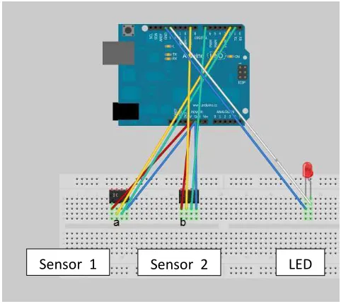
Figure 3 show how the sensors, LED are connected to the microprocessor. For the sensors, both sensors send and receiver pin are connected to the digital pin. Since the sensors convert the analog data (sound wave) to digital data, the digital pin at Arduino make the data to be calculated. LED alarm also use the digital pin also to make the blinking alarm. Arduino is operated at 12 volt. [3].
ZRT-VBSS programming use the advantage of Arduino rooted code such as pinMode, digital Write, Millis [4]. By using the rooted code, the programming uses less line of code. This allows the microprocessor to work faster and the program use less memory to execute. ZRT-VBSS also use the loop command in order to make the system work continuously without any unintended delay or stop. Once system is connected to ECU engine, ZRT-VBSS is then automatically program to perform. This makes the system easy to be monitored and to make any adjustment because the data can then be set as real time interval. The ZRT-VBSS programming is set to have the delays of two sensors are set to 50 milliseconds. The delay should be set to 500 milliseconds to make sure the alarm will trigger only if the relative speed the car to the object faster than 28.8 km/h.
2 Meter
Fig. 3: ZRT-VBSS circuit diagram.
Experimental Result
The experiment is conducted by attaching the ZRT-VBSS unit onto the side mirror of Malaysia national passenger car. The experiment is performed under the following conditions during. [4]
1. Static Test. The first test is conducted to test the ability of ZRT VBSS that distinguish between static objects and vehicles. ZRT-VBSS only issue a warning sign if the vehicle within the blind spot area. Figure 4 shows the ZRT VBSS does not give false alarms as it pass thorough series of road divider.
2. Vehicle speed at 60 km/h and 100 km/h. The second test is performed at the speed of 60 and 100 km/h to ensure that the ZRT-VBSS is capable to spot the blind area under standard normal driving conditions. Figure 5 shows that as the other car enters the blind spot area, the LED light blinking to warn the driver about the situation of having a vehicle in the blind spot area.
3. Overtake Test. ZRT VBSS can also distinguish if the vehicle is in the blind spot in the cut as shown in Figure 6. This test will ensure that the ZRT-VBSS able to identify the whether the incoming car have less potential to collide.
Fig. 4: ZRT-VBSS during static test Fig. 5: ZRT-VBSS during 60 km/h test
Sensor 1 Sensor 2 LED
Fig. 6: ZRT-VBSS during overtake test
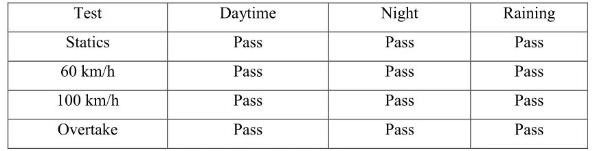
Experimentation was not only conducted during daytime, but also at night and raining driving condition. The system shows a very performance for all the test condition as shown in Table 1 below.
Table 1: ZRT-VBSS Road Test Results
Test Daytime Night Raining
Statics Pass Pass Pass
60 km/h Pass Pass Pass
100 km/h Pass Pass Pass
Overtake Pass Pass Pass
Conclusion
ZRT-VBSS provides a better solution for vehicle rear-quarter blind spot phenomenon. The result from the experimental investigation demonstrate a good performance of ZRT-VBSS to alarm the driver when there is a high risk object in the rear-quarter blind spot area with the capability to remove false alarm the system and reliable in real usage.
Acknowledgement
This work is supported by the University Teknikal Malaysia Melaka (UTeM). This financial support is gratefully acknowledged.
References
[1] Hampel, P. and Ridder, K., Vehicle bind spot contribute to child fatalities, group says, http://www.kidsandcars.org (2004).
[2] Rajedra Prasad Mahapatra and K. Vimal Kumar, Panoramic Sensor Based Blind Spot Accident Prevention System,World Academy of Science, Engineering and Technology Vol. 25 (2009).
[3] Arduino, http://www.www.arduino.cc (2012)
[4] A. Jenkins, Remote Sensing Technology for Automotive Safety, Microwave Journal, 24-52, (2007 )