MOVIC2014
The evaluation of a locking function for a vertical stage
electrostatic actuator
Mariam MD GHAZALY* and Kaiji SATO**
*Department of Mechatronics Engineering, Faculty of Electrical Engineering, Universiti Teknikal Malaysia Melaka, Hang Tuah Jaya, 76100 Durian Tunggal, Melaka Malaysia
E-mail: [email protected]
** Interdisciplinary Graduate School of Science and Engineering, Tokyo Institute of Technology, 4259-G2-17 Nagatsuta Midori-ku, Yokohama 226-8502, Japan
Abstract
The present paper validates the effectiveness of the characteristic switching as a locking function for a vertical motion multilayer thin electrostatic actuator supported by only lubricating oil. In the electrostatic actuator, the friction forces often deteriorate the response and positioning accuracy of a control system, especially when the lightweight electrode layers are supported by only lubricating oil. However, the contact condition between the electrode layers can be changed by the attractive forces resulting from the driving signal waveforms, which consequently influences the frictional effect. The large frictional effect that is generated is useful as a locking function which is needed to precisely maintain the stage position especially in vertical motion stages. In this paper, suitable driving signal waveforms for switching between two frictional conditions (i.e., low friction for the wide and fast motion and high friction for the fine motion with a large holding force) are examined and clarified for the vertical motion stage. First, the working principles and experimental setup of the electrostatic actuator in the vertical motion stage are discussed. Then, the open-loop characteristics under the vertical motion stage are discussed based on the frictional effect. Lastly, the resultant effects of the driving signals on the vertical motion characteristics were evaluated, which concluded with the discussion in the signal selection on demand as the locking function.
Keywords : Multilayer electrostatic actuator, Lubricating oil, Locking function, Holding force and Vertical motion stage.
1. Introduction
adjusting two types of frictional force have been proposed; i.e. (a) high friction force for the limited working range motion with a large holding force and (b) low friction force for full working motion. Therefore, in this paper, the usefulness of the electrostatic actuator supported by lubricating liquids with a locking function is demonstrated using a vertical motion stage.
In Section 2, the structure, working principles, and experimental setup of the electrostatic actuator in the vertical motion stage are described. In Section 3, the open-loop characteristics under the vertical motion stage are discussed based on the relationships between the driving signals, the working ranges and the frictional effect. Finally, the conclusions are presented in Section 4.
2. T
he structure of the vertical motion stage
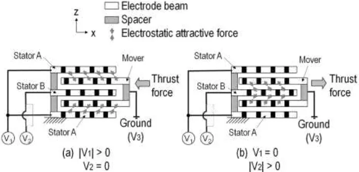
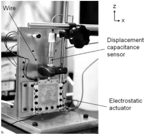
The electrostatic actuator presented in this paper is a variable-capacitance motor type actuator that has two mover layers (Ghazaly and Sato, 2013). Fig. 1 shows a schematic diagram of the experimental two-layer electrostatic actuator. Only lubricating oil is used to reduce the friction between the electrode layers for easy fabrication and maintenance. Silicone oil with a viscosity of 10 mPa∙s and a dielectric constant of 2.65 is used as the lubricating oil. Fig. 2 shows the front and side view structure of the experimental two-layer electrostatic actuator in the vertical motion for examining the locking function. The material used for the electrodes is phosphorus bronze. The electrodes are laminated with 30m thickness low density polyethylene flat films as isolation films to reduce the friction between the electrode layers. This film is selected due to the high wettability of the film. The lubricating liquid is expected to easily be maintained between the electrode layers using high wettability film in the vertical setup. The mover mass is 5.43g. The nominal silicone oil thickness inserted in the gap is 0.123mm. To realize bidirectional motion, voltages V1 and V2
are applied to Stator A and Stator B, whilst voltage V3 is set to zero and applied to the mover. Stator B is set to be
shifted by 500um to Stator A. Under this condition, the initial condition of the mover is set to be shifted by 250um to Stator A and Stator B in the z-direction. The working range is equal to the length between the beam centers of Stators A and B in the z-direction, i.e. 500 m. Only lubricating oil is used to reduce the friction between the electrode layers for
[image:2.595.126.479.428.598.2]easy fabrication and maintenance. Silicone oil with a viscosity of 10 mPa∙s and a dielectric constant of 2.65 is used as the lubricating oil.
Fig. 1: Driving procedure for the bi-directional motion of the electrostatic actuator (Ghazaly and Sato, 2012).
Fig. 2: Structure of the electrostatic actuator in the vertical motion stage
3. The locking function & the driving signal characteristics
In this section, the motion characteristics of the electrostatic actuator with the linear low density polyethylene film as the isolated film are discussed in detail in order to validate the suitable driving signal for the vertical motion stage. In the experimental actuator, the 10mPa.s silicone oil is used as the selected lubricating liquid with the dielectric constants of 2.65. The attractive forces resulting from the driving signal influence the contact condition between the electrode layers (i.e., the frictional effect), when the lightweight electrode layers are supported by only lubricating oil. When the driving signal is applied to the electrode layers, the applied voltage signal between the electrode layers provides the charge to the electrode layers and the attractive force between them. The attractive force reduces the gap between the electrode layers and causes the mechanical contact between them. This behavior increases the frictional force, which is useful as a locking function. Hence, a suitable driving signal has the potential to adjust the frictional effect for fine motion with a large holding force and a wide and fast motion.
[image:3.595.200.447.453.681.2]4
5
6
7
8
9
10
0
1000
2000
Holding voltage = 1kV
Time s
V
2V
0
1000
2000
V
1V
Holding voltage = 1kV
8
10
12
14
16
D
is
p
la
c
e
m
e
n
t
m
[image:4.595.171.465.83.265.2]1
m
p-pTable 1: Specifications of the electrostatic actuator
Parameters Value Electrode width and length (mm) 50 50 Beam pitch (mm) 1.5 Spacer (mm) 50 6.5 Electrode thickness (mm) 0.1 Spacer thickness (mm) 0.4 ETFE film thickness (mm) 0.014 Electrode + ETFE film thickness (mm) 0.128 Thickness of assembled mover (mm) 0.656 Thickness of assembled stator (mm) 1.184 Gap between electrodes (mm) 0.244 Estimated silicon oil thickness (mm) 0.244 Mover mass (g) 5.22
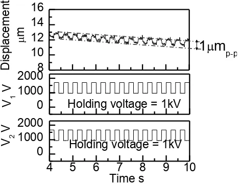
In (Ghazaly and Sato, 2013), two driving modes has been proposed for the horizontal motion stage and the driving signal profiles for adjusting the frictional effect have been discussed; i.e. (a) fine driving mode using the fine driving mode signal for the fine motion with a large holding force and (b) wide driving mode using the wide driving mode signal for wide and fast motion. For adjusting the frictional effect for fine driving mode with a large holding force, the normal signal is useful, although the working range is limited. In this paper, the limited working range is referred to as the fine working range. In order to benefit from the large holding force, the normal signal with a continuous constant voltage (referred to as the holding signal) is applied to the actuator which is introduced in (Ghazaly and Sato, 2013). Fig. 4 shows the displacement characteristics using the fine driving mode signal under the vertical stage. Fig. 4 shows that the displacement is kept at 1mp-p after the period of 4s.
Fig. 4: Displacement characteristics using the fine driving mode signal under the vertical stage; motion characteristic is kept at 1mp-p.
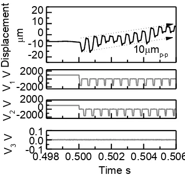
[image:4.595.188.425.423.603.2]voltage. It can be depicted that the upward is approximately 20mp-p which is slightly larger than the downward motion
18mp-p. This difference is considered to be caused by the effect of gravity. In the upward motion, the center of gravity
of the mover is shifted upward, which result in a larger displacement. In addition, during the upward motion the wires holding the mover becomes contracted which indirectly helps to produce large displacement in compared with the downward motion. In the downward motion, the wires are extended and constrained by the stiffness of the wire, which limits the displacement range.
[image:5.595.87.511.135.358.2](a) Upward-unidirectional motion, (b) Downward-unidirectional motion, applied voltage 1.8kV applied voltage 1.8kV
Fig. 5: Motion characteristics of the actuator in the vertical stage using negative impulse signal; control period, Tcs=0.5 ms
after applying the 1kV holding signal.
-20 -10 0 10 20
10mp-p
-0.10.0
0.1
0.498 0.500 0.502 0.504 0.506 Time s -20000 2000 -20000 2000 V 3 V V 2 V V 1 V D is p la c e m e n t m
Fig. 6: The reciprocating motion characteristics of the actuator in the vertical stage using negative impulse signal with an applied voltage 1.5kV; control period, Tcs=0.5 ms after applying the 1kV holding signal.
4. Conclusions
In summary, this paper focused on validating the effectiveness of two driving signals: i.e. (a) fine driving mode signal and (b) wide driving mode signal i.e the negative impulse signal with the 1kV holding signal to a vertical motion stage which enables a locking function for the vertical motion stage. In the vertical motion stage, the holding function is crucial for maintaining precise motion due to the influence of gravity. Both the driving signals are useful for the control of the precision positioning stage based on these characteristics; i.e. working range and frictional effect. As a result, the suitable driving signal has the potential to adjust the frictional effect for fine motion with a large holding force which acts as a holding function; and a wide and fast motion. The two driving modes; i.e., the fine driving mode
-20
-10
0
10
20
-0.1
0.0
0.1
Time s
-2000
0
2000
-2000
0
2000
0.498 0.500 0.502 0.504 0.506
V
3V
V
2V
V
1V
D
is
p
la
c
e
m
e
n
t
m
20
m
p-p
-20
-10
0
10
20
18
m
p-p
-0.1
0.0
0.1
Time s
0.498 0.500 0.502 0.504 0.506
[image:5.595.206.388.404.582.2]for fine motion with a continuous holding force and the wide driving mode with the 1kV holding voltage for the full working range of motion have been examined in detail. The open-loop experimental results show that the two driving modes can be derived and switched using suitable driving signals. As a conclusion, these prove the negative impulse signal with the 1kV holding voltage was useful to reduce the frictional effect due to the attractive force and to drive the actuator in the vertical motion under the wide working range.
Acknowledgement
This research and publication is supported by Tokyo Institute of Technology (Tokyo Tech.) and Universiti Teknikal Malaysia Melaka (UTeM). Authors are grateful to Tokyo Tech. and UTeM for supporting the research.
References
Hwang I. H., Lee Y. G., Lee J. H., A micromachined friction meter for silicon sidewalls with consideration of contact surface shape, J. Micromech. Microeng. 16 (2006); pp. 2475–2481.
Lin W., Ann N. K., Ng L. E., Concepts for a class of novel piezoelectric self-locking long-stroke actuators Precision Engineering (2002); 26: pp. 141–154.
Cueffl M., Defaÿl E., Rey P., Rhun G. L., Perruchot F., Ferrandon C., Mercier D., Domingue F., Suhm A., Aïd M., Liu L., Pacheco S., Miller M., A fully packaged piezoelectric switch with low voltage actuation and electrostatic hold. IEEE 23rd International Conference on Micro Electro Mechanical Systems (2010); pp. 212–215.
Ghazaly M. M., Sato K. Characteristic switching of a multilayer thin electrostatic actuator by a driving signal for an ultra-precision motion stage. Precision Engineering. 37 (2013); pp. 107-116.