ABSTRAK
ABSTRACT
DEDICATION
AKNOWLEDGEMENT
Bismillahirrahmanirrahim. With the name of Allah the most Gracious and the most Merciful.
LIST OF TABLES
3.1 The shortcut button in motion tool bar. 41
4.1 Individual parts of the stamping machine. 44
4.2 Individual parts of the Automatic tapping machine. 45
4.3 Individual parts of the Automatic tapping machine. (continued) 46
4.4 Individual parts of the rotary table. 47
4.5 Individual parts of the rotary table. (continued) 48
4.6 Individual parts of the rotary table. (continued) 49
4.7 Individual parts of the magazine table. 50
4.8 Individual parts of the magazine table. (continued) 51
4.9 Individual parts of the mold section 1. 52
4.10 Individual parts of the mold section 1. (continued) 53
4.11 Individual parts of mold section 2. 54
4.12 Individual parts of mold section 3. 55
4.13 Cycle time of conventional process for automotive retainer 63
4.14 Cycle time of conventional process for automotive retainer 64
4.15 Cycle time of conventional process for automotive retainer 65
4.16 Average of cycle time for Conventional process. 66
4.17 Cycle time of automated process for automotive retainer 67
4.18 Average of cycle time for automated process approached. 70
4.19 Total cycle time of the production process. 70
LIST
OF FIGURES
1.1 Complete part of Automotive retainer (Sourse : United 1
1.2 Fuel tank upper that assembled with automotive retainer. (Source : United
Vehicles Industries Sdn. Bhd.) 2
2.1 A perspective view of automotive oil pump fixing ring. ("Automotive oil pump
fixing ring," 2013) 7
2.2 Aperspective view of fuel tank filler pipe retainer. (Craig & Cupp, 1983) 8 2.3 The detail design and application of retainer ball bearing. (Principle
Engineering) 10
2.4 The detail process and shaped for stamping process. (Dalessandro, Lorenz, &
Carr, 1998) 12
2.5 The view of threading fitting. (Groh, 1965) 13
2.6 The geneva mechanism. (Choubey & Rao, 1983) 16
2.7 The perspective view of an improved cross bar transfer press. (Bruns, 1993) 17
2.8 Robotic press machine. (Vieth R, 1999) 18
2.9 The icon of the CATIA Software. (Source : Internet) 19
2.10 Optimal part-programming in industry. (Source :
http://www.flowwaterjet.com/en.aspx) 20
2.11 The Arenasoftware. (Source : Internet) 21
3.1 Project flowchart 26
3.2 Stamping process cycle time study. (Source : United Vehicles Industries Sdn.
Bhd.) 28
3.3 Stamping process cycle time study. (Source : United Vehicles Industries Sdn.
4.23 3D view of shaft. 51
4.24 3D view of repellent. 51
4.25 3D view of bottom mold. 52
4.26 3D view of bottom die. 52
4.27 3D view of top mold. 52
4.28 3D view of big stripper. 53
4.29 3D view of small stripper. 53
4.30 3D view of bottom mold. 54
4.31 3D view of die. 54
4.32 3D view of top mold. 54
4.33 3D view of bottom mold. 55
4.34 3D view of jig. 55
4.35 Isometric view of the stamping machine assembly. 56
4.36 Isometric view of the automatic tapping machine. 57
4.37 Isometric view of the rotary Table. 58
4.38 Isometric view of the magazine Table. 59
4.39 Isometric view of the mold section 1. 59
4.40 Isometric view of the mold section 2. 60
4.41 Isometric view of the mold section 3. 60
4.42 Schematic view of the plant layout. 61
LIST OF ABBREVIATIONS, SYMBOLS AND
NOMENCLATURE
CATIA - Computer aided three-dimensional interactive application
AMS - Automated manufacturing system
CAD - Computer aided drawing
ICG - Interactive computer graphics
3D - Three dimensional
CAM - Computer aided manufacturing
CAE - Computer aided engineering
FMS - Flexible manufacturing system
DOF - Degree of freedom
1
CHAPTER 1
INTRODUCTION
1.1 Background
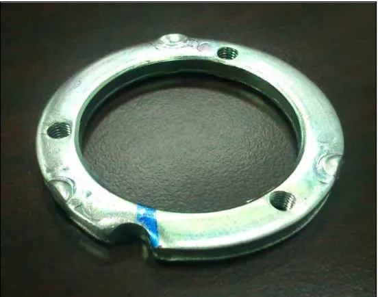
In manufacturing the automotive fuel tank, there are few child parts required and used to complete the construction of one fuel tank. The child parts that are assembled in the fuel tank includes the tube breather, pipe fuel inlet, plate Fuel Tank separating, sub-part tank fuel, Support Fuel sub-tank, Reinforcement fuel tank upper and clamp. One of the prominent and important child parts is the bracket. The bracket is known as an automotive retainer that uses to attach the fuel pump assembly. The automotive retainer is assembled at the upper fuel tank at the lid of the fuel pump assembly.
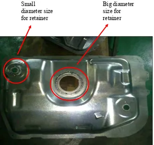
Figure 1.1 and Figure 1.2 below show the automotive retainer in the fuel tank.
From the Figure 1.2, the dimension sizes of the automotive retainer is divided into two sizes. The big size dimension is attached at the center of fuel tank while the smaller size is at the edge of the fuel tank. The function is same as a bracket which is to attach the pump oil fuel and the tube of pump oil fuel.
In order to produce the parts of the fuel tank, the appropriate process manufacturing, material selection and manufacturing system approach is concerned to get a better fuel tank in case for the quality of the product. This is because the automotive fuel tank is the safety product used by users. The production of the fuel tank needs to be of high quality manufacturing process involving the child part, system production and quality inspection. The material used to produce the fuel tank is made of sheet metal. This sheet metal is shaped using stamping machine.
Small
diameter size for retainer
Big diameter size for retainer
The production rate of automotive retainer is important to make sure the part is not released before the assembly process occurs. The production rate of these parts must be consistent that will be effect the process cycles time, the manufacturing stamping process and the raw material. The process stamping that involved in the several types such as the blanking process, chamfering process, form/embossing process, sheaving process, piercing process, flattening process and tapping process.
In this industry, the current production process of automotive retainer is using the big stamping machine and the conventional tooling. For examples, the process used the stamping machine is also used for producing the retainer and other process to achieve the desired parts. In addition, the mold and die can have changed to produce the other parts as well as follow the company production planning. The operation of the stamping machine needs at least one or two operators to operate the stamping machine which includes the material input and output. After the stamping process finished, the next process will be followed.
1.2 Problem statement
At present, the current production line approach used in the industry for the production of the automotive retainer is through the conventional process. Typically in the conventional process of an automotive retainer, stamping machine is widely used. This is because of the large size of the stamping machine that is able to produce this part. Hence, this will change the process method of stamping machine for another process part. In brief, the problems identified due to the conventional production line are as follows:
(a) Longer cycle time to complete the process.
(b) Lower production rate.
To overcome the elaborated issues, automated production system is seen as a potential replacement system. The company can improve the production rate of the automotive retainer through the design of the automated production line and reduce the cycle time of the process.
1.3 Objectives of Project
To complete this project, three objectives have been identified. The objectives of this project are:
(a) To review and analyze the current production approach of the automotive retainer in industry.
(b) To propose the design conceptual of automating the production of the automotive retainer using rotary indexing mechanism.
(c) To analyze the cycles time and production rate for the proposed automated production approach.
1.4 Scopes and Limitations of Project
The main idea of this project is to automate the production of the automotive retainer. The proposed mechanism for this project will utilize the rotary indexing mechanism. In this project, CATIA software and SolidWorks software will be used to design the propose automated production line. Once the production line has been designed, analysis of the cycle time will be analysed for the process involving both the current method and the automated method will be performed.
1.5 Structure of the Report
The report is organized into five chapters. Chapter 1 will introduces the project which includes background of project, problem statement, objectives to be achieved throughout the project, scopes, as well as the limitation of the project.
Chapter 2, literature review begins by discussing several terms related to automated production of the automotive parts, especially for retainer fuel tank, which is followed by the system types of automated production that suiTable for the process involved and the types of the material transfer mechanism on available design.
Chapter 3, methodology chapter discusses the method employed upon completing the project. Mixed methodologies comprising qualitative and quantitative approached are used to gather data. Flowcharts also will be shown for this chapter. Project design and analysis are elaborate more to get the outcomes of the design of the production. The simulation the automated production process will be created and analysed to get the quantitative data such as the standard cycle time.
Chapter 4 is about the result, analysis and discussion with will discuss the outcomes of the design and analysis of the automated production line, process selection to be automated for appropriate process, engineering concept for manufacturing production and the quantitative data of the cycle time process.
2
CHAPTER 2
LITERATURE REVIEW
This chapter summarizes the current state of knowledge and information about the automating production of the automotive retainer using the rotary indexing mechanism. The most important part of this chapter is the review of several scope of the automotive retainer. Related issues regarding the production process system includes the comparison between the automated process and the conventional process. The review of cycle time and production rate of the production is also being discussed. The basic idea of the material transfer in production process system is also included. At the end of this chapter, there will be brief information of the design and simulation of the automated process production which is created by using either CATIA or SolidWorks software is included in this chapter.
2.1 Retainer
2.1.1 Automotive retainer
In the automotive application, the retainer allows the use of components car such as at a body panel as cited by (Purcell, 1978). The retainer comprises a strip attached to the support structure and is conFigured to hold the body panel. Typically in the fuel tank, pipe filler oil and body car are widely used.
2.1.1.1Automotive retainer at fuel tank
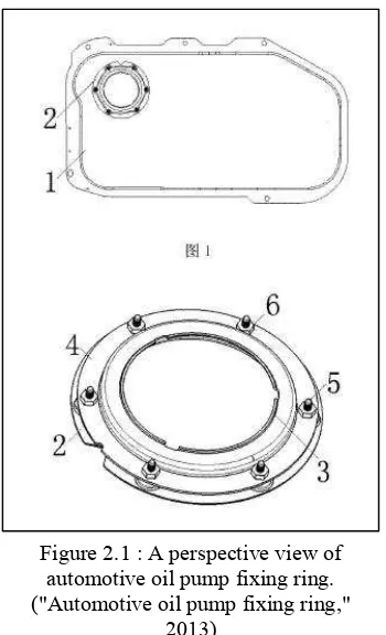
Automotive oil pump fixing ring was invented and shown in Figure 2.1 ("Automotive oil pump fixing ring" 2013)). It provides the design of automotive oil pump which is attached at fixed ring set on the upper tank. Existing car fixed ring mostly have a steel ring with bolt hole circle on the plate and then fitted with bolts.
In this design invention, there are some issues encountered for the existing fixed wrong pump. The issues include the work piece operation, the part is easy to loose and remove, low processing efficiency and high production costs, the retainer ring is
Figure 2.1 : A perspective view of automotive oil pump fixing ring. ("Automotive oil pump fixing ring,"
not quite to locate the oil pump, impede to ensure the accuracy of the assembly and operational effectiveness, the stability is poor and the quality of the product is different. In the technical problem, the utility model is implemented to achieve a simple assembly operation and assembly of high precision purposes. To solve this problem, the utility model approaches such as provided a car fixed ring pumps including pumps fixed ring body, the body of the pump unalterable ring is provided on the upper tank, the pump oil pump is provided on the cap retainer ring body between the pump body and the stationary ring pump gland bolt and spot by spot welding nuts.
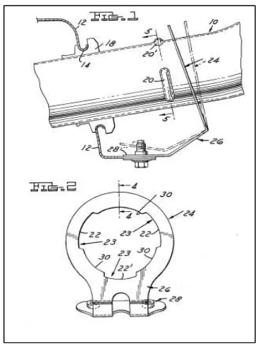
2.1.1.2Automotive retainer at pipe filler oil
Craig and Cupp (1983) invented the support of the fuel fill pipe for an automotive type fuel tank. Moreover, it relates to a retainer that resists fill pipe withdrawal as well as supports and locates the lower end of the fill pipe relative to the fuel tank. A partially exploded view of the fuel tank filler pipe retainer is illustrated in Figure 2.2 as follows.