Development of Automated Irrigation System for
Production Field : Fuzzy Timer Control
Satyanto K.Saptomo*, Budi I. Setiawan*, Ahmad Tusi** , Marzan A.Iskandar***
*Department of Civil and Environmental Engineering, Bogor Agricultural University (IPB), FATETA-IPB, Kampus IPB Darmaga, Bogor, Indonesia, tel/fax: +622518627225
(email:[email protected])
**Agricultural engineering, Faculty of Agriculture, University of Lampung (UNILA) ***The Agency For the Assessment and Application Technology (BPPT)
Corresponding Author : Satyanto K. Saptomo
Abstract: The aim of this research is to develop an automation system for irrigation to be implemented on existing irrigation facility. A fuzzy timer control (FTC) technique was developed for application in water level control. FTC is the modification of the original fuzzy logic control (FLC) which have been widely known and been applied in various control systems. The FTC was applied in simulation using water balance analysis of weather, evapotranspiration and land condition information. Simulation was conducted for dry season and rainy season, using weather data input as disturbance to the system. The set point was chosen based on the water level in the irrigation practice used in SRI cultivation. FTC showed good performance in the anticipation of water level fluctuation to maintain water level near the setpoint, but faced difficulty in heavy rainfall event especially in heavy rain season. During dry season, the FTC showed better performance and ability to maintain water level near the desired level. The simulation was conducted using spreadsheet programmed with macro basic language. The simulation also gave the irrigation and drainage capacity of 1.3 lt/sec.ha for rainy season and1.6 lt/sec.ha for dry season, with each performance index of 11871.5 and 4225.4, which values are the results of optimization during the simulation.
Keywords: Simple Fuzzy Control, irrigation, drainage, hydrology
1. INTRODUCTION
Global climate change and changes in rainfall patterns has increased the uncertainty of water availability. Facing the increasing uncertainty, efforts of efficiency in the water utilization, including water efficiency of irrigation for agriculture is needed. It is necessary to find technologies that can improve the efficiency of water utilization to avoid unnecessary water loss and reduce the total amount of water that should be reserved for the agricultural sector. One method that can be used to accomplish this is the automation of irrigation.
Irrigation automation system is a part of the water management system, which includes irrigation and drainage. One example of this system was developed in the study of development of water control systems in wetlands (Setiawan, et. Al. 2002, Saptomo et.al, 2004) that used pump to drain water into or out of land used for agriculture. A slightly different system
was also applied to computer simulations of wetland water management System of Rice Intensification (SRI) (Arif et.al 2009).
One of the problems faced in the application of this technique is the difficulty to obtain technology, such as water pumps or doors that can be well adjusted electronically to deliver variable flow rates. This is due to non-availability in the domestic market as well as difficulties to widely implement the technology in the infrastructure available, and especially in Indonesia. When using common AC water pumps, the easy way to implement is to use the two position control system either manually or automatically using sensor. Another way is to use a timer that will turn on the pump at a time and a certain time period, such as for intermittent irrigation.
off in a very short time. In addition, on-off system is also less able to provide good control results. Timer system is an open-loop system that does not take reference from input measured by sensor and still has possibility to over- or under-irrigate.
Both of these systems can be combined to create a control technique that uses two position actuator while using the system timer in a closed loop control system, by utilizing fuzzy theory that is easily applied to the control system. This study aimed to implement the fuzzy logic control system in setting the irrigation timers.
2. MATERIALS AND METHODS
2.1. Simple Fuzzy Logic Control System (SFLC) and Fuzzy Timer Control (FTC)
Fuzzy logic controller FLC is a control methodology based on Fuzzy Theory. In general FLC would follow steps of input-fuzzyfikation-inference-defuzzyfication-output. The schemematic for fuzzy logic control is as in Fig. 1.
Fig 1. Fuzzy Logic Control (FLC)
In this case, water level or water table is the quantitative input to the fuzzy system, sensed by sensor as pressure.
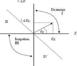
Simple fuzzy logic control (SFLC) is a variant of FLC, proposed by Iskandar et. al. (1999). The basic concept of control system is usually obtaining 2 parameters: error and delta error. Error is the differences between the actual value and set point. Delta error is the changing of that condition. In the SFLC the control system based on “if-then” logic was translated into one set of control system represented by polar system coordinate as in Fig. 2.
Fig.2. Coordinate polar system for SFLC
Where, 2 K 1 2 K
K E f E
D (1)
K K 1 K
D
E
cos
(2)Dk is magnitude and θk is degree in coordinate polar
system, f1 is control parameter to increase
performance of system. The coordinate polar system can be explained as follow:
X axis show the difference between actual value and set point or error (Ek), Y ordinate showed the
changing of error or delta error (ΔEk). Ek was
calculated by equation as follow:
sp a
k h h
E (3)
where, ha is actual water level (cm), hsp is set point
of water level (cm) and ΔEk was calculated by
equation as follow:
1 ki ki
k
E
E
E
(4)where, Eki is error at time i, Eki-1 is error at time i-1.
If the value of Ek and ΔEk fall into first (I)
quadrant, drainage should be done. Otherwise, if the value of Ek and ΔEk on in third (III) quadrant,
irrigation should be done. On the second (II) and fourth (IV) quadrants are alternating conditions, where irrigation and drainage will be done. The diagonal line in II and IV quadrants showed the balance condition where ha and hsp are equal (the
expected condition). The quantity of drainage or irrigated water was determined by fuzzy inference. From this polar system θk and Dk will be determined
and the membership function of θk and Dk can be
suggested explained by these Fig. 3 and the magnitude by Fig.4.
Based on those member functions above, can be derivate the control signal of Uk by this equation:
m D P N P N K
U
U
(5)Where Um is maximum number of control signal,
and μP = 1 –μN so equation 6 can be wrote:
m D N
K
(
1
2
)
U
U
(6)Um and Uk are equal with the quantity of irrigate or
drainage water. For the practice, those can be actuated by number of pumps, opened gated of canal, etc. In this case, Um and Uk are irrigation or
drainage rate (cm/day).
of on-off operation of equipment used in closed loop control. This control system adopts SFLC, with the output is given is the time of of operation or a timer and the type of operation (irrigate, drain, stop). The control process is done almost the same as FLC, except that one control signal generated will be further interpreted as a signal operation (Uop) and the
length of operation time (top). Uop follows the rules
in Table 1
Table 1 Operation Uop
U
opIrrigation
Pump
Drainage
Pump
1
on
off
0
off
off
-1
off
on
Fig. 3 Membership function of phase angle (degree)
Fig. 4. Membership function of magnitude
The control signal Uk is a signal output from the
SFLC. The relationship between the Uk, Uop and top
are as follows
Uk = Uop * top (7)
Sehingga dapat dilihat bahwa adalah nilai absolut dari Uk, sedangkan Uop adalah tanda didepannya
(positif (+1) atau negatif satu (-1)). Nilai top dapat
dibuat dalam sebuah skala normal misalnya 0-1 yang mewakili rentang tertentu, dalam hal ini 0-1440 menit (24 jam).
It can be seen that top is the absolute value of the Uk,
while the Uop is the sign in the front : (positive (+1)
or negative one (-1)). The value of top is normalized
0-1 representing a specific range, in this case 0-1440 minutes (24 hours)
.
2.2.Computer Simulation of FTC Water level control.
The FTC system described above is implemented to control water in the land. This system is assembled on sensors, controllers and actuators. The will detect the status of water level in the controlled location, and the signal is fed to the controller. Control system will do the processing of sensory information and generate control signals as output to the actuator. The actuator will actualize this control action in the form of irrigation pumps or valves with known capacity. Actuator operation is determined by the Uop dan top resulted from FTC. Computer
simulations was carried out following closed-loop control scheme as in Fig. 5.
Fig. 5. Closed-loop irrigation control scheme
Simulation model can be seen in Fig. 6 below. Land is assumed to have a water channel around it. High water on both these channels into the soil around the boundary. Water level on both channels is what will be regulated by a control system to provide ground water as needed. In a particular depth, the soil is assumed haveing semipervious layer that withstand percolation as commonly found in paddy fields
.
Simulation is done by calculating Water Balance. The components that affect the water balance in this simulation is the inflow (irrigation and rainfall) and outflow (drainage, percolation, seepage, evapotranspiration, and surface run off) and are represented as in the following equation:
HPt = HPt-1 + RFt + Qt– ETt– Pt– ROt (8)
Where,
HPt = depth of standing water in rice fields at the time
of day (mm)
HPt-1 = depth of standing water in rice fields on day t-1
(mm)
Qt = amount of irrigation water (+) or drainage (-), on
day t (mm)
ETt = evapotranspiration (mm)
Pt = the amount of water lost through percolation
(mm)
ROt = runoff that occurs in paddy fields, if any (mm)
t = period of time
In this simulation only water level in the canal surounding the land is assumed to be sensed and controlled. Programming and simulation conducted using the language of basic macros in spreadsheet software.
3. RESULT AND DICUSSION
Computer simulations was conducted using
climate data, soil evaporation
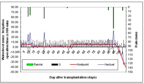
and physical data obtained for the location of Bekasi in 2009. The simulation was done for two seasons namely dry season (June to August) and rainy season (January to April) during the rice planting SRI. In the simulation, the automatic system works with varying setpoint, depend on the plants age and represet the water condition prefered by the land. This variation follows the patter of water management in the system of rice intensification (SRI). Setpoint changes can be seen in Fig. 7 and 8.Water balance in dry season (Figure 6) is marked with less supply of water from the rain and the automatic irrigation system worked intensively to keep the water level at the desired level. It can be seen that the level of water level can be maintained and it fluctuates around the setpoint in every age of the plant. The rain that occasionally fell to the outpouring of high lead levels of water level rises far above the setpoint, but was soon overcome by a drainage system.
In the rainy season, heavy rainfall and long rainy days happen which caused drainage system work more intensively. Field water level seems difficult to be kept at the desired setpoint. But the automatic controller seems to work well anticipating these fluctuations and the influence of rain.
Fig 7. Water control simulation in dry season
Fig 8. Water control simulation in rainy season
Table 2 Control Parameter
Table 2 shows some parameters in the control. Discharge Q for different cropping seasons possess different values, resulted from the search of optimum Q by using solver function in a spreadsheet program to find the optimum value. However, the value of Q is at the same magnitude for both irrigation and drainage. The amount of water supplied or removed from the land then would depend on operation time top resulted from the control process.
Performance index PI is a parameter commonly used to evaluate the performance of control systems. PI obtained from the sum of squares E during the control simulation. A good performance is obtained when the PI minimum, the smaller the PI indicates better performance. PI is used in the optimization process control systems mentioned above.
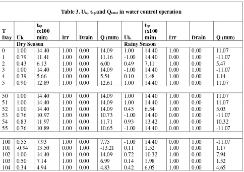
Table 3 shows the values of Uk, top and Q total in a
water level control operation. Q in this table is the total water supplied in a single day in mm. This value is the result of
multiplying the t
opwith
water delivering capacity of pumps or valves
The simulation results shown that high rainfall is still a problem that cannot be fully handled the FTCPARAMETER Rainy season Dry Season
PI 11871.5 4225.4
Q (mm/day) 11.1 14.1
system. This is influenced by the capacity of irrigation / drainage equipment. To improve accuracy, the simulation needs to be done on a smaller time scales such as hours or minutes. Furthermore, it should be considered which way of water is controlled in each case. For instance on particular agricultural land, irrigation is required due to lack of surface water or rain water. However, when it is raining the water will be retained as long as possible on land. In this case a special drainage system is unlikely necessary. In the other hand, for agriculture in the wetland area, possibly at a given moment the drainage is needed because constant inundation will lead inhibit planting. Therefore, the application of water level control need to be tailored to the needs.
Field experiments are the next stage which will be done as a continuation of this research, to obtain effectiveness of the automated water level control system based on fuzzy timer techniques. One of which is being prepared is the use of the wireless controller module with cellular system for irrigation control in experimental field. FTC system is expected to increase the efficiency of controlling the operation of this wireless control system since energy and cost in wireless connection will be minimized with FTC.
4. CONCLUSION
Fuzzy timer control system has been applied to control water levels and used in the simulation of water level control in the SRI cropping pattern. The system can work well in accordance with control algorithms that are used. The simulation results show that the control system has limitations in controlling water level, especially to preserve the level at the setpoint on the days with quite heavy rain.
Simulation software developed for this simulation can also be used to find the capacity of irrigation / drainage needed for the location regarding size and physical condition of certain land, and let appropriate design for specific locations.
This research is yet to be followed by a field experiment to test the effectiveness of automatic water control based on fuzzy timer techniques presented in this paper.
5. REFERENCES
Arif C., S.K.Saptomo, B.I.Setiawan, Marzan Aziz Iskandar. 2009. Water Table Controlling in Paddy Field Using a Simple Fuzzy Control System. PAWEES International Conference on Promising Practices for the Development of Sustainable Paddy Fields Bogor: October 7-9.
Table 3. Uk, top and Qtotal in water control operation
T
Day Uk
top (x100
min) Irr Drain Q (mm) Uk
top (x100
min) Irr Drain Q (mm)
Dry Season Rainy Season
0 1.00 14.40 1.00 0.00 14.09 1.00 14.40 1.00 0.00 11.07 1 0.79 11.41 1.00 0.00 11.16 -1.00 14.40 0.00 1.00 -11.07 2 0.43 6.13 1.00 0.00 6.00 0.49 7.11 1.00 0.00 5.47 3 1.00 14.40 1.00 0.00 14.09 -1.00 14.40 0.00 1.00 -11.07 4 0.39 5.66 1.00 0.00 5.54 0.10 1.48 1.00 0.00 1.14 5 0.90 12.89 1.00 0.00 12.61 1.00 14.40 1.00 0.00 11.07
50 1.00 14.40 1.00 0.00 14.09 1.00 14.40 1.00 0.00 11.07 51 1.00 14.40 1.00 0.00 14.09 1.00 14.40 1.00 0.00 11.07 52 1.00 14.40 1.00 0.00 14.09 0.45 6.54 1.00 0.00 5.03 53 0.76 10.97 1.00 0.00 10.73 -1.00 14.40 0.00 1.00 -11.07 54 0.83 11.97 1.00 0.00 11.71 0.93 13.42 1.00 0.00 10.32 55 0.76 10.89 1.00 0.00 10.65 -1.00 14.40 0.00 1.00 -11.07
Iskandar, M.A., Y. Susanti, S.K. Saptomo dan B.I. Setiawan. 1999. Pengendalian Muka Air Tanah menggunakan Sistem Kendali Fazi Sederhana (Groundwater Control with Simple Fuzzy Control System). Buletin Keteknikan Pertanian.
13(1):66~74. (In Indonesian)
Saptomo, S.K., B.I. Setiawan and Y. Nakano. 2004. Water Regulation in Tidal Agriculture using Wetland Water Level Control Simulator. The CIGR Journal of Scientific Research and Development. Manuscript LW 03 001.
Satyanto K.Saptomo
1, Budi I. Setiawan
1,
Ahmad Tusi
2, Marzan A.Iskandar
3 1Departemen of Civil and Environmental Engineering, Bogor Agricultural University (IPB)
FATETA-IPB, Kampus IPB Darmaga, Bogor, email:[email protected]
2
Agricultural engineering, Faculty of Agriculture, University of Lampung (UNILA)
3
The Agency For the Assessment and
Application Technology (BPPT)
INTRODUCTION
MATERIAL AND METHODS
Conclusion
land, and let appropriate design for
specific locations.
This research is yet to be followed by a
field experiment to test the effectiveness of
automatic water control based on fuzzy timer
techniques presented in this paper.
Acknowledgement
This research was partially funded by Bogor
Agricultural University through I-MHERE B2c
Project and by Directorate General of Higher
Education, Ministry of Education, Republic of
Indonesia, through International Colaboration
and Publication Grant.
Daftar Pustaka
Arif C., S.K.Saptomo, B.I.Setiawan, Marzan
Aziz Iskandar. 2009. Water Table
Controlling in Paddy Field Using a Simple
Fuzzy Control System. PAWEES
International Conference on Promising
Practices for the Development of
Sustainable Paddy Fields Bogor: October
7-9.
Iskandar, M.A., Y. Susanti, S.K. Saptomo dan
B.I. Setiawan. 1999. Pengendalian Muka
Air Tanah menggunakan Sistem Kendali
Fazi Sederhana (Groundwater Control
with Simple Fuzzy Control System).
Buletin Keteknikan Pertanian.
13(1):66~74. (In Indonesian)
Saptomo, S.K., B.I. Setiawan and Y. Nakano.
2004. Water Regulation in Tidal
Agriculture using Wetland Water Level
Control Simulator. The CIGR Journal of
Scientific Research and Development.
Manuscript LW 03 001.