DOI: 10.12928/TELKOMNIKA.v15i1.4685 273
Compound Control of Electromagnetic Linear Actuator
Based on Fuzzy Switching
Zhu Jianhui, Wang Cheng*, Dai Jianguo
School of Traffic Engineering, Huaiyin Institute of Technology, Huai’an 223003, Jiangsu, China *Corresponding author, e-mail: [email protected]
Abstract
Due to the motion control system of electromagnetic linear actuator (EMLA) is a nonlinear system with poor controllability; single control strategy has been difficult to meet the requirements of its control. A compound control strategy based on inverse system control (ISC) and proportional-integral (PI) is designed in this paper. Switching between two algorithms, which is based on the fuzzy rules, prevents the control algorithm to jitter and jump. System model is built under Matlab/Simulink to do simulation analysis. The designed controller is integrated into the system simulation model and the system software of digital signal processor (DSP) controller. Simulation and test results show that the compound control strategy using fuzzy switching rules achieves the smooth transition of two control algorithms, and the goal of any position location, and continuous adjustment in 0~4mm lift. Positioning accuracy is up to ± 0.02mm, while the response time is less than 10ms.
Keywords: electromagnetic linear actuator, fuzzy switching, inverse system, PI
Copyright © 2017 Universitas Ahmad Dahlan. All rights reserved.
1. Introduction
With linear position servo’s characteristics of high performance, high response and high
precision, EMLA has been widely used in many fields, such as direct drive type servo valve [1], electromagnetic gas distribution mechanism [2], and automatic transmission (AMT) etc. While get applied at the same time, it has also put forward higher requirement to its control strategy. On the one hand, it can meet the performance index of control accuracy as far as possible in the steady state response; On the other hand, response should be fast enough to shorten the adjust time of reaching the target position as far as possible in the transient response.
Regarding motion control requirement of high performance, In literature [3], Liu and Chang uses inverse system control algorithm, and also applies to electromagnetic valve actuator. It obtains a high response but also has a good seating control at the same time. In order to improve its anti-interference ability and system robustness, An auto disturbance rejection control algorithm is used which based on extended state observer in [4]. In addition, the fuzzy control of direct torque control of induction motor studied in depth [5]. It has outstanding contribution to the improvement and progress of system performance. Using a single control strategy has a good control performance on the one hand, but there is still room for improvement in adaptability [6]. But the compound control strategy is adopted, when switching the algorithm, due to the selection of switching position, it will cause system jitter, also easily causes instability. But if using fuzzy rule to switch of compound algorithm, it can achieve a smooth transition between different algorithms. So multi model control has attracted much attention. Issam Salhi [7] and M.Kalyan Chakravarthi [8] etc. conduct deep research on multi model PI controller. Baozhu Jia has come up with a fuzzy switched PID (FS-PID), which combines the advantages of fuzzy control and PID control [9]. Fuzzy PID is used to increase the transient response speed, while traditional PID to improve the tracking error of steady state. Ahmed Rubaai applies the fuzzy switch position controller to the traditional bang-bang control [10] which improves the control precision of system, especially in the case of interference, which can still be able to ensure superior control performance.
controllers. The designed controller is applied to the motion control system of EMLA, in order to meet the performance requirements of system response and accuracy.
2. System Scheme and Principle
EMLA is a kind of element which can directly convert electrical energy into mechanical energy of linear motion form without the need of any intermediate conversion device, also called "linear servo motor". It can be used as the executive component of all kinds of automatic control system, and has a characteristic of compact structure, high power density, large thrust, and high control precision etc.
The structure of motion control system for EMLA is shown in Figure 1. It is mainly composed of system controller, system actuator, system sensor, and display part of system output. The controller uses high performance controller of TMS320F2812. System sensor includes current sensor and displacement sensor. And the display part of output mainly contains host computer PC and related software.
PWM ADC
DSP—LAN DSP TMS320F2812
Control Board
Power Driver Current Sensor Displacement Sensor
PC System Sensor System
Controller
Actuator System Output and
Display
EMLA
Output
Figure 1. Structure of Motion Control System of EMLA
Its working principle is system controller mainly completes signal acquisition and control signal output of each sensor, and also communication of host computer at the same time. Through the corresponding software design, it achieves a variety of control algorithms functions. The small power signal output by controller is amplified by power drive module, and controls high power signal. EMLA, which used as a controlled object of system, can realize the double closed loop control lift through control of current and the position of actuator. The host computer part completes output and display, and also storage and processing of final data output.
ISC PI Control
ISC
Hold Open Hold Close Hold
Target Xr1
Closed Position Xr
Switching Position xr Switching Position
xr1
0 Open Time T0
Close Time
T1 Next Cycle
PI Control
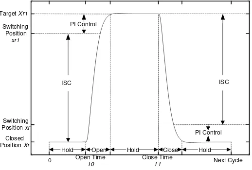
In order to realize the compound control of EMLA, the lift control of EMLA is divided into three stages: opening, closing and keeping. Control algorithm has two kinds: inverse system control and PI control which is shown as Figure 2.
Upon receipt of the opening instruction, firstly EMLA cancels holding force, and enters opening stage from holding position, till up to the specified target lift, and keeps this position after reaching the scheduled target. Upon receipt of the closed command, it executes shut down procedure, enters closing phase, and remains closed after fully closed until the next work cycle is turned on.
In opening phase, before the target lift smaller than Xr1, it uses the control parameters of inverse system. When it is bigger than switch position xr1 until reaching the target lift Xr1, PI control is used. In closing phase, upon the receipt of closing instruction, and before reaching the switch position xr, the inverse system control is used. When it is smaller than the switch position xr, but reaching the closed position Xr, PI control is used. Using fuzzy switching rules to automatically realize switching between position Xr1 and xr.
3. System Model and Compound Controller Design 3.1. System Mathematical Model
The motion control system for EMLA includes circuit subsystem, magnetic field subsystem, and mechanical subsystem. Coupling relationship between different parts is shown as Figure 3. When power is supplied to circuit subsystem from power system, subsystem outputs current to magnetic field, an electromagnetic force generated by the interaction between current and magnetic field is transferred to mechanical subsystem. Drive actuator straight part overcomes external resistance to generate motion, and make motion speed transfer to circuit subsystem for the calculation of back EMF. Finally, the control of actuator lift is realized.
Circuit Subsystem R、L
Magnetic Subsystem (Φ(t))
Mechanical Subsystem (m、k)
i(t) Fm X(t)
dx(t)/dt E(emf)
e(t) Electric Signal
Figure 3. Each Subsystem Coupling Between the Control System
Circuit subsystem converts the input voltage of EMLA into current. It can be equivalent to a series connection of resistors and inductors.
in
di U = Ri + L + e
dt
(1)
In the equation, the counter electromotive force E can be expressed as
e
e = BlNv = K v
,U
in is supply voltage, i is the current through coil, R and L is the coil resistance and inductance respectively, e is the back EMF generated by cutting magnetic lines when coil moves in the air gap field,K
e is the constant of counter electromotive force, v is the coil velocity.Magnetic subsystem is the interaction between current and magnetic field generated by the circuit subsystem, and generates electromagnetic force, and then realizes the linear motion of moving parts. So the driving force of movement comes from the Lorentz force of self loading coil in the air gap magnetic field. According to the Lorentz force of electric coil in magnetic field, the electromagnetic force equation of EMLA is:
m b m
In the equation,
k
b is structure coefficient,B
is coil magnetic induction strength,l
iseffective length per coil magnetic field,
N
is the number of coil turns,k =k B lN
m b is the constant of EMLA driving force.EMLA has to overcome friction and inertia force during runtime. Inertia force is the product of quality and acceleration of EMLA moving parts, in addition to load force here. Therefore, the force balance equation of EMLA can be expressed as:
2
m 2 v L
d x dx F = m + k + F
dt dt
(3)
In the equation, m is the quality of EMLA coil assembly,
x
is mover displacement,k
v isdamping force coefficients of moving parts in a magnetic field,
F
L is load external disturbance force.Complex equation of (1), (2)and (3), the motion equations of EMLA is:
2
2 in
m b m
m v c L
di
U
Ri
L
e
dt
F
k B lNi
k i
d x
dx
F
m
k
k x
F
dt
dt
(4)
3.2. Inverse System Design
The inverse system achieves transformation from nonlinear system to linear system by means of a method of nonlinear feedback or dynamic compensation. By the definition of inverse
system, suppose nonlinear system is
1, the initial state of the system isx t
( )
0
x
0, theoperator that maps the system
1 from the input to the output is
, and
is values andarbitrary continuous functions in a domain.
maps tou
, that is
y
( ) , it is expressed as:( )
y
u
y
(5)Then
1 is called
rank inverse system,
is original system. The inverse system and original system is connected in series to realize decoupling process of nonlinear system. System after reconstruction is called pseudo-linear system, and it can be controlled by the theory of linear system. The input variables of control system for EMLA is voltageu
and the location for output isS
, according to system voltage balance equation and differential equations of motion, it takes the derivative of output, makes it explicitly contain voltageu
, and finally the expression ofu
can be induced as follows:''' '' '
m
m m
mL
BL
u
S
S
k S
IR
k
k
(6)3.3. PI Controller Design
0 0
( ) ( ) ( 1)
( ( ) ( )) ( ( 1) ( ))
[ ( ) ( 1)] ( ( ))
k k
j j
U k U k U k
T T
Kp e k e j Kp e k e j
Ti Ti
Kp e k e k Ki e k
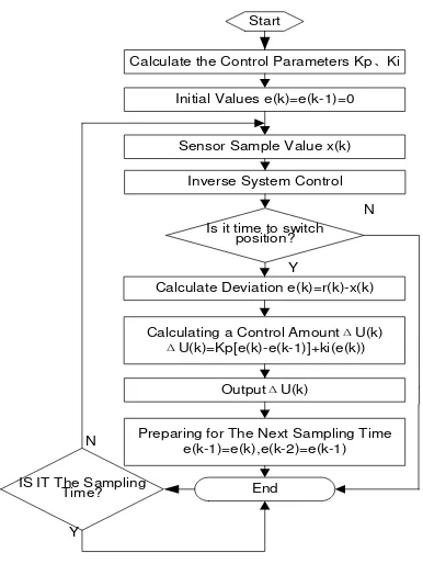
(7)In the equation, is sample number, is scaling factor, is integral coefficient,
Δ ( )is output control increment at sampling time, ( ) and ( −1) is output control increment at sampling time of and −1, ( ) and ( − 1) is error value at sampling time of and -1. Algorithm flow is shown in Figure 4 as follows:
Start
IS IT The Sampling Time?
Calculate the Control Parameters Kp、Ki Initial Values e(k)=e(k-1)=0
End Sensor Sample Value x(k)
Calculate Deviation e(k)=r(k)-x(k) Calculating a Control AmountΔU(k)
ΔU(k)=Kp[e(k)-e(k-1)]+ki(e(k)) OutputΔU(k)
Preparing for The Next Sampling Time e(k-1)=e(k),e(k-2)=e(k-1)
Is it time to switch position?
Y N
Y
N Inverse System Control
Figure 4. Flow Chart of Control Algorithm
3.4. Switching of Compound Control Algorithm
The motion control of EMLA uses two compound controls of inverse system control and PI control, and the core of complex control is smooth switching between two methods. There are generally two ways of switching. The first one is to set a threshold value in advance, and automatic switching by the program. However, when using this switching mode, on the one hand it is difficult to choose the right switch value, and also difficult to solve the contradiction between system rapidity response and overshoot, on the other hand, it is difficult to guarantee switching without disturbance from one control method to the other one, and thereby extends system regulation time. The second one is that the switching mode based on fuzzy rules. The first feature of this method is the control amount acting on controlled object is weighted mixed output of two kinds of controllers, and combines the advantages of both controllers. Secondly, in the control process, it can realize auto-adjust of two controls’ weight. Fuzzy switching principle is shown as Figure 5(a), e is input and u is output. Membership function is shown as Figure 5(b). Fuzzy switching rule is as follows:
If e is “z(e)” then “u” is “uIS” ELSE “u” is “uPI”
Inverse System Controller + -yf X(t) Y(t) Incremental PI Controller Fuzzy Switching E M L A e uPI uIS u
-a a e
z 1
0
(a) (b)
Figure 5. Fuzzy Switching Rules
The value of a in Figure 5(b) is set according to system requirements, in order to get different control intensity component. Its control algorithm is as follows:
= ( )
PI z e
(8)
1 ( )
IS z e
(9)
PI PI IS IS
PI PI IS IS PI IS
u u
u u u
(10)
In the equation, PI is output intensity factor of PI controller at the input bias of e, and
IS
is output intensity factor of inverse system at the input bias of e, and uPI is output of PI controller, uIS is output of inverse system control.
From the above analysis, only when system enters steady-state response, and error is very small, PI controller plays a major role at this time. In the transient stage, the controller of inverse system control plays a major role. Therefore compound controller keeps advantages of PI and the traditional inverse system controller. It achieves a smooth transition between the two control methods, and avoids the weakness of general complex control.
4. Simulation and Test
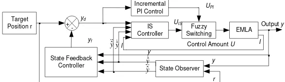
In order to verify the feasibility of algorithm, simulation model under Matlab/Simulink is build, which makes a connection of the above obtained inverse system, PI, state observer, and state controller. The block diagram of simulation model is shown as Figure 6, while given the target position, it uses inverse system control at initial time. When approaching the target position and meeting fuzzy switching conditions, it loads into the output UPIof PI control, and forms control amount to EMLA. Through control algorithm of PI, and according to error size, it constantly automatically adjusts volume control, and ultimately achieves a stable output.
Target
Position r IS Controller Incremental
PI Control
EMLA Control Amount U
+ Output y
State Observer State Feedback Controller
.
.
.
.
.
I I ˆ y ˆ y ˆ y ˆ y -yf yd.
y y r Fuzzy Switching UIS UPIFigure 6. Block Diagram of Controller Structure
4.1. Simulation Results
lift in any position, it makes divide at the setting lift of 0~4mm, and the initial process is divided into 8 lifts, 0.5mm as a section. And then verify the smaller lift, such as 16 sections of lifts. Test results only gives the simulation and test results of 8 lifts process. Other lifts can also achieve this effect. It could continuously adjust up to 0~4mm lift, and adjustable program is not limited to the illustrated figure, which is not to repeat here.
Table 1. Simulation Parameters
Parameter Value
Coil Resistance/Ω 4
Coil Inductance/mH 1.6 Moving Mass/Kg 0.036 Actuator Force Constant/(N/A) 11.3 Counter Electromotive Force Constant/(V/m/s) 11.3
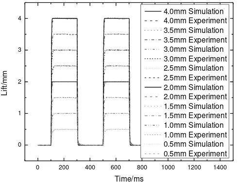
Figure 7 are given simulation and experimental results in continuous lift. There is 8 setting positions, that is, 4.0mm, 3.5mm, 3.0mm, 2.5mm, 2.0mm, 1.5mm, 1.0mm, and 0.5mm. The period of each work cycle is 400ms, and it keeps 200ms after opening, then it is closed.
0 200 400 600 800 1000 1200 1400 0
1 2 3 4
L
if
t/
mm
Time/ms
4.0mm Simulation 4.0mm Experiment 3.5mm Simulation 3.5mm Experiment 3.0mm Simulation 3.0mm Experiment 2.5mm Simulation 2.5mm Experiment 2.0mm Simulation 2.0mm Experiment 1.5mm Simulation 1.5mm Experiment 1.0mm Simulation 1.0mm Experiment 0.5mm Simulation 0.5mm Experiment
Figure 7. Simulation and Experimental Results under Continuous Lift Process
As can be seen from Figure 7, in different target locations, experiment results and
simulation have a good consistency. It verifies algorithm’s suitability under the change of lift.
When the target lifts change, there is no need to re-change control parameters. As can be seen from the results of comparison, and test results are shown that, the rise time of reaching steady state is slower than simulation. In the actual control, in order to prevent overshoot, over the target position, and bump after close, it has to reduce the scaling factor, and exchanges the accuracy of steady state for sacrificing settling time. Experimental error statistics are shown in Table 2. Results can be drawn that the same set of parameters can achieve different lift, and steady-state error is in the range of ± 0.02mm. The feasibility of algorithm is verified. When the switching position selects fuzzy switching, using complex control strategy of PI and inverse system, compared with using only a single inverse system control method, it can automatically adjust error at the steady state until steady-state error meets performance requirements.
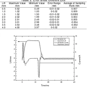
Talble 2. Error under Different Lifts
Lift /mm
Maximum Value /mm
Minimum Value /mm
Error Range /mm
Average of Sampling Point /mm 0.5 0.52 0.49 -0.01-0.02 0.007 1.0 1.02 1.00 0-0.02 0.009 1.5 1.52 1.50 -0.01-0.02 0.0095 2.0 2.02 1.99 -0.01-0.02 0.003 2.5 2.51 2.49 -0.02-0.01 0.005 3.0 3.01 2.98 -0.02-0.01 -0.004 3.5 3.53 3.48 -0.02-0.02 -0.002 4.0 4.00 3.97 0-0.02 -0.01
0 10 20 30 40
-5 -4 -3 -2 -1 0 1 2 3 4 5
Simulation Lift Experiment Lift Simuliation Current Experiment Current
Time/ms
L
if
t/
mm
-10 -5 0 5 10 15
C
u
rre
n
t/
A
Figure 8. The Position and Current of 4mm lift
As can be seen from Figure 8, in the high-speed running state, when using compound control strategy, system can quickly reach the target position, response time is 3.7ms, test matches simulation results.
4.2. Test Comparison under Different Control Strategies
In order to verify the validity of the designed control strategy, experimental designs three control strategies for control effect of a lift. Target lift is set as 3mm, and control algorithm uses inverse system, inverse system plus PI, and inverse system plus PI plus fuzz switching. The test results are shown in Figure 9.
0 5 10 15 20 25 30 35 40
-0.5 0.0 0.5 1.0 1.5 2.0 2.5 3.0 3.5
10 2.5
3.0 3.5
30 35 40 -0.1
0.0 0.1 0.2
Li
ft/
mm
Time/ms IS+PI
IS+PI+Fuzzy Switching IS
It can be seen from the effect of these three control strategies, using single inverse system control strategy, when parameter is not through repeated manual adjustment, but only in accordance with fixed parameters, its output result of control exceeds the target lift, which is because each parameter control selects other lift values, it could lead control result beyond target position. But after increasing PI compensation, the control strategy based on erro of PI could stabilize the final steady state value at target lift. As long as there is an error, it plays the role. So PI can increase the accuracy of control, but the system is prone to overshoot. Through dispatch the fuzz switching, it can achieve the target lift at steady state, but also can prevent overshoot and oscillation.
From the control effect point of view, only using the control scheme of inverse system control, response time is smaller than the other two control strategies. This is the advantage of inverse system control, but the steady state accuracy is worse than the other two schemes. And after increasing of PI, in order to increase system adjusting time, error must continue to reduce, so it can achieve the steady-state accuracy of requirements at the expense of sacrificing response time.
5. Conclusion
A combined control scheme of inverse system and PI is designed in this paper. It combines fast response of inverse system control with precision advantages of PI control, and realizes the smooth switching between two control algorithms based on the fuzzy switching rule. It achieves the positioning goal of EMLA at any position in the lift of 0~4mm. Comparison of three control schemes, inverse system, PI plus inverse, and fuzzy switching plus inverse system shows that response time is fastest, and steady state error is also the largest by using single control strategy of inverse system, but while using control method of inverse plus PI plus fuzzy switching, it is better than the other two, especially in the control of steady state error. It could reach ± 0.02mm. Although response time is slightly slow, it can still be able to meet the control target less than 10ms.
Acknowledgements
This work was supported by the National Natural Science Foundation of China (Grant No. 51505171), Natural Science Foundation of Colleges in Jiangsu Province (Grant No. 15KJD460003), and Science and Technology Support Programs of Huai’an (Grant No. HAG2014026).
References
[1] Zhu Jianhui, Chang Siqin. Modeling and simulation for application of electromagnetic linear actuator
direct drive electro-hydraulic servo system. Proceedings of IEEE International Conference on Power
and Energy (PECon 2012). 2012: 430-434.
[2] Liu Liang, Chang Siqin. Improvement of valve seating performance of engine’s electromagnetic valvetrain. Mechatronics. 2011; 21(7): 1234-1238.
[3] Liu Liang, Chang Siqin. Motion control of an electromagnetic valve actuator based on the inverse system method. Proceedings of the Institution of Mechanical Engineers, Part D: Journal of
Automobile Engineering. 2012, 226(1): 85-93.
[4] Shi Xinxin, Chang Siqin. Precision motion control of a novel electromagnetic linear actuator based on a modified active disturbance rejection controller. Proceedings of the Institution of Mechanical
Engineers, Part I: Journal of Systems and Control Engineering. 2012; 226(5): 606-614.
[5] Dong Ming, Yong-qi Tang, Hai-liang Song Bing-jie Wang. Study of an Improved Fuzzy Direct Torque Control of Induction Motor. TELKOMNIKA (Telecommunication Computing Electronics and Control). 2013; 11(4): 691-698.
[6] Jannati M, Sutikno T, Idris NRN, Aziz MJA. A Novel Technique for Fault-Tolerant Control of Single-Phase Induction Motor. TELKOMNIKA (Telecommunication Computing Electronics and Control). 2015; 13(3): 783-793.
[7] Salhi I, Doubabi S, Essounbouli N, Hamzaoui A. Application of multi-model control with fuzzy switching to a micro hydro-electrical power plant. Renewable Energy. 2010; 35(9): 2071-2079. [8] Chakravarthi MK, Venkatesan N. Experimental Validation of a Multi Model PI Controller for a Non
Linear Hybrid System in LabVIEW. TELKOMNIKA (Telecommunication Computing Electronics and
[9] Jia Baozhu, Ren Guang, Long Gang. Design and stability analysis of fuzzy switching PID controller. Proceedings of IEEE International Conference on 2006 6th World Congress on Intelligent Control and Automation (WCICA 2006). 2006: 3934-3938.