69:3 (2014) 73–79 | www.jurnalteknologi.utm.my | eISSN 2180–3722 |
Teknologi
Integrating Servo-Pneumatic Actuator with Ball Beam System based on
Intelligent Position Control
Muhammad Asyraf Azmana, Ah ad Athif Mohd Faudzia,b*, Nu a Di Mustafaa, Khairuddin Osmana,c,Elango Natarajand
aDepartment of Control and Mechatronics Engineering, Faculty of Electrical Engineering, Universiti Teknologi Malaysia, 81310 UTM Johor Bahru, Johor, Malaysia
bCentre for Artificial Intelligence and Robotics (CAIRO), Universiti Teknologi Malaysia, 81310 UTM Johor Bahru, Johor, Malaysia
cDepartment of Industrial Electronics, Faculty of Electronic and Computer Engineering, Universiti Teknikal Malaysia Melaka, Durian Tunggal, Melaka, Malaysia
dSchool of Mechanical Engineering, Kolej Universiti Linton, Mantin, Negeri Sembilan, Malaysia
*Corresponding author: [email protected]
Article history
Received :10 March 2014 Received in revised form : 28 April 2014
Accepted :15 May 2014
Graphical abstract
Abstract
The purpose of this paper is to design a controller that can control the position of the cylinder pneumatic stroke. This work proposes two control approaches, Proportional-Integral-Derivative Fuzzy Logic (Fuzzy-PID) controller and Proportional-Derivative Fuzzy Logic (PD-Fuzzy) controller for a Servo-Pneumatic Actuator. The design steps of each controller implemented on MATLAB/Simulink are presented. A model based on position system identification is used for the controller design. Then, the simulation results are analyzed and compared to illustrate the performance of the proposed controllers. Finally, the controllers are tested with the real plant in real-time experiment to validate the results obtained by simulation. Results show that PD-Fuzzy controller offer better control compared to Fuzzy-PID. A Pneumatic Actuated Ball & Beam System (PABBS) is proposed as the application of the position controller. The mathematical model of the system is developed and tested simulation using Feedback controller (outer loop)-PD-Fuzzy controller (inner loop). Simulation result is presented to see the effectiveness of the obtained model and controller. Results show that the servo-pneumatic actuator can control the position of the Ball & Beam system using PD-Fuzzy controller.
Keywords: Pneumatic actuator; ball and beam; fuzzy controller
© 2014 Penerbit UTM Press. All rights reserved.
1.0 INTRODUCTION
Pneumatic systems are widely used in automation industries and in the field of automatic control due to its advantages such as high power-to-weight ratio, cost effective and uses air as a clean medium to drive them. Moreover, they have faster response, safe to be used in high temperatures or in nuclear environments. Pneumatic give advantages because gases are not subjected to the temperature limitations [1]. However, pneumatic actuators also have some drawback of control difficulties due to the nonlinearities involved such as compressibility of air, the valve dead zone and friction. As a result, it is difficult to achieve accurate position control for the pneumatic actuator.
The merits of pneumatic systems have motivated many researchers for years to propose different control approaches to achieve higher accuracy and better dynamic performance. Many of these works focused on the intelligent controllers such as fuzzy logic controllers (FLC) and neural networks controllers. Over the past two decades, the fields of fuzzy controller applications has broadened to
be included in many industrial control applications and significant research work has supported the development of the fuzzy controllers [2]. The idea of fuzzy logic control (FLC) was originally introduced by Zadeh [3] and been applied in an attempt to control systems that are structurally difficult to model [4]. In 1975, Mamdani and Assilian [5] developed the first fuzzy logic controller (FLC), and it successfully implemented to control a laboratory steam engine plant. Mamdani’s pioneering work also introduced the most common and robust fuzzy reasoning method, called Zadeh– Mamdani min–max gravity reasoning. Takagi and Sugeno [6] introduced a different linguistic description of the output fuzzy sets, and a numerical optimization approach to design fuzzy controller structures. These controllers were not only used for controlling pneumatic actuators but also for many other applications such as robot, motor and inverted pendulum [1].
This paper describes an implementation of Fuzzy Logic Controller (FLC) with combination of conventional PID controller. The design procedure utilizes MATLAB® Fuzzy Logic toolbox and
the Fuzzy Logic toolbox is the ability to take fuzzy system directly into SIMULINK® and test them out in a simulation environment [7]
and real-time experiment using Data Acquisition (DAQ) card. This paper aims to design fuzzy logic controllers which are derivative type fuzzy logic controls (PD-Fuzzy) and proportional-integral-derivative type fuzzy logic control (Fuzzy-PID). Sugeno type of fuzzy logic will be used as the fuzzy inference system which it works well with linear techniques (e.g., PID control). The performance of these controllers will be compared an analysed for both simulation and real-time experiment. To this end, the performance of these controllers will be tested to a simulated ball & beam system. The ball & beam system is viewed as benchmark control engineering setup whose underlying concept can be applied to stabilization problem for diverse system such as the balance problem dealing with goods to be carried by a moving robot, spaceship position control system in aerospace engineering and to test pneumatic actuator to its limit.
The ball & beam system is commonly used a mechanical combination of motor, gear and pull belt and also using servo motor as a actuator to control the angle of the beam [8, 9]. The system is designed based on mathematical model using several methods which are Lagrangian method, Newton’s second law method and also converting to transfer function [7, 8]. In this paper, by Newton’s second law method, the mathematical model is derived to describe the dynamic behaviour. Based on the feedback law, a suitable controller is designed. The controller is a rate and a position feedback where the purpose of this system is to have the ball position, xo(t) follow the reference position, xi(t).
The rest of this paper is organized as follows. In section 2 the selected plant used for this research is described. Section 3 explains the controller strategies using Fuzzy-PID, PD-Fuzzy and feedback controller. Then, section 4 discusses the simulation and experimental results of the closed-loop tracking performance of the pneumatic actuator and the simulation results for Pneumatic Actuated Ball & Beam System (PABBS). Finally, conclusions are given in the last section.
2.0 SYSTEM DESIGN
This research discusses two design plants. The first plant is the Servo-Pneumatic Actuator Plant and the second plant is the Ball and Beam Plant. The first plant model is obtained by using system identification technique whereas the second plant is obtained using mathematical model. Both plants will be combining as a system called Pneumatic Actuator Ball and Beam System (PABBS).
2.1 The Servo-pneumatic Actuator Plant
The plant used in this research is a servo-pneumatic actuator developed by KOGANEI® used for research purpose [10]. This
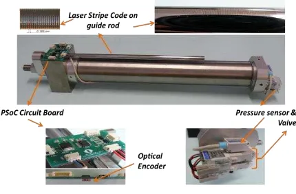
cylinder is a modified cylinder from a linear double acting cylinder (KOGANEI – HA Twinport Cylinders) with two air inlets and one exhaust outlet as shown in Figure 1. A PWM signal is injected to the valve in order to control the pressure inside the chamber. The two on/off valves are connected only to one chamber (chamber 1) with configuration of the valves operation as in Table 1. This PWM signal for valve control is designed in order to give a similar pulse generated using an 8-bit PWM modules found on a PSoC microcontroller and this will make the implementation of the controller in the PsoC microcontroller easier in the future.
Figure 1 The pneumatic actuator and its parts
Table 1 Valve configuration
Valve Operation Valve Condition Valve 1 Valve 2
Cylinder Stop OFF OFF
Actuator moves left
direction OFF ON
Actuator moves right
direction ON OFF
No operation ON ON
In order to design the controller, the same method is used as [11] to obtain a linear model of the pneumatic actuator. A DAQ card PCI/PXI-6221 (68-Pin) board is used for interfacing the plant with a computer by using MATLAB as the platform. A lower sampling,
s
Ts0.01 time is used in order to get better response and more data. From the system identification method, a discrete-time open loop third order ARX model was obtained in Equation (1).
1 2 33 2
1 1
1
0.1593 0.3957
1.555 1
0.001172 0.001951
0.0008224
z z
z
z z
z z
A z B
o
o (1)
The third-order model will represent the nearest model of the true plant. From the MATLAB System Identification Toolbox, Auto-Regressive with Exogenous Input (ARX) model from input-output data will be obtained. From Equation 1, the system is stable because all the poles of the open-loop discrete transfer function lies within the unit circle of the z-plane and best fitting criteria is more than 90% after model validation process in system identification.
2.2 Ball and Beam Plant
The control objective is to give accurate position of the ball by applying a suitable stroke length of the pneumatic actuator. The ball can be maintained in a certain steady state from unsteady state by adjusting the angle of the beam through the movement of the pneumatic actuator. The position of the ball is obtained by measuring the voltage from the resistance sensor while the angle of the beam which depends on the pneumatic actuator stroke is recorded by the position of the encoder. It is difficult to control the velocity and acceleration of the ball directly due to the friction coefficient between ball and beam as well as to control the pneumatic actuator stroke which is highly nonlinear.
as position sensing in rolling without sliding. The proposed system parameter is defined by the acceleration of gravity as g, the radius of ball as R, mass of the ball as m, choosing the beam angle as α, the pneumatic actuator stroke length as h, the beam length as l and moment of inertia of ball asJ, respectively. The simplified system parameters are listed in Table 2.
Figure 2 (a) PABBS (b) free-body diagram
The nonlinear mathematical representation of the system can be derived by applying the Newton’s second law of motion. In the system, by neglecting the frictional force we encounter two forces which are translational force, Ftx acting along the x-direction which is due to gravity and rotational force, Frx resulting from the torque produced by the rotational acceleration of the ball. These two forces can be summaries as below [9]:
tx
F =Force due to translational motion
rx
F =Force due to ball rotation
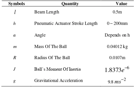
Table 2 PABBS parameters
Symbols Quantity Value
l
Beam Length 0.5mh Pneumatic Actuator Stroke Length 0 – 200mm
α Angle Depends on h
m Mass Of The Ball 0.04012 kg
R Radius Of The Ball 0.0107m
J Ball’s Moment Of Inertia
1
.
8373
e
6g Gravitational Acceleration 9.8ms2
Consider the free-body diagram shown in Figure 2(b), denoting the acceleration
2 2
dt x
d along x asx, Hence force due to
translational motion as in Equation (2). x m
Ftx (2)
We can denote torque due to the ball rotation as below:
x
Hence; re-arrangement of Equation (3) produces the following expression: and α as a beam angle. Then substitute Equation (2) and Equation (6) into Equation (7), we obtain
Further re-arrangement of Equation (8) produces the following expression:
For the proposed ball and beam system, the beam angle, as in Equation (9) is depends on the pneumatic actuator stroke length,
h. From Figure 2 (a), we can express the beam angle as below:
3.0 RESULTS AND DISCUSSION
This section discusses several controllers design for the servo-pneumatic actuator plant and ball & beam plant. For the proposed system, the control system design requires two feedback loops which are an inner loop for the pneumatic actuator and an outer loop for ball position control as shown in Figure 3. The purpose of inner loop is to control the pneumatic stroke length, h which actuates the beam (control the angle, α). This inner loop controller, C2 should be
designed so that the pneumatic actuator can give a good and stable position control. The outer loop, C1 uses the inner feedback loop to
control the ball position.
Figure 3 Pneumatic actuator ball and beam system (PABBS) controller designed
3.1 Pneumatic Actuator Controller Design (Inner Loop)
Two fuzzy-type controllers will be discussed which are the Proportional Derivative Fuzzy Logic controller (PD-Fuzzy) and the second controller design is the Proportional-Integral-Derivative Fuzzy Logic controller (Fuzzy-PID). Both controller designs are combination of two controllers which are Fuzzy controller and conventional PID controller.
3.1.1 Fuzzy Logic Control Scheme
A block diagram of a fuzzy logic system is shown in Figure 4. The fuzzy controller is composed of three parts which are fuzzification, rule base and defuzzification.
Figure 4 Fuzzy logic block system
3.1.2 Fuzzification
The inference system has three linguistic variables which are the two inputs (error and rate of change of error) and the output (control signal) as shown in Figure 4. The error is defined as:
)
And the change of error is defined as follows:
)
Figure 5 PD-Fuzzy logic controller
Figure 5 shows the PD-Fuzzy Logic Controller design for close loop fuzzy control system which has single output, called incremental control output and is denoted byuPD(nT). It contains a number of sets of parameters that can be altered to modify the controller performance. From Figure 5, Keand K∆e are error gain (Proportional error input scale) and error rate gain (error Derivative input scale) and K∆u is the output scale for the controller [12].
Figure 6 Fuzzy-PID controller
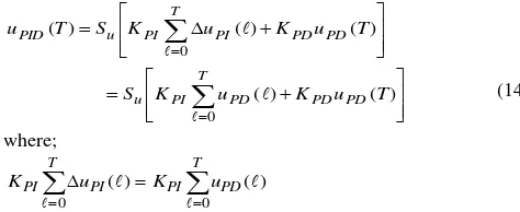
Fuzzy-PID controller used in this paper is based on two inputs FLC structure with Coupled Rules [2]. By combining both PI and PD actions as shown in Figure 6, a two input Fuzzy-PID controller can be formed. With additional gains KPD and KPI, the final Fuzzy-PID control signal shown in Figure 6 is given by Equation (14).
Both of the controllers using the same design of fuzzy logic which using Triangular-shaped built-in membership function. The linguistic labels used to describe the fuzzy sets were ‘Large Negative’ (LN), ‘Small Negative’ (SN), ‘Zero’ (Z), ‘Small Positive’ (SP) and ‘Large Positive’ (LP).
3.1.3 Rule Base
The fuzzy control rule is in the form of: If x is A and y is B then z=f(x, y), where A and B are fuzzy sets in the antecedent, while z=f(x,y) is a crisp function in the consequent. The rule base structure used the Sugeno type. It can be seen in the output membership function where it consist of three fuzzy sets where ‘Valve 2’ (V2), ‘Off’ (off) and ‘Valve 1’ (V1). The value of V2 = -255, off = 0 and V1 = 255 which is similar to PWM concept where fully open and fully close for the valve. Table 3 shows the relationship between the input and output (fuzzy logic rules) in tabular linguistic format.
Table 3 Rule bases for PD-Fuzzy and Fuzzy-PID controller
Error
3.2 Ball and Beam Controller Design (Outer Loop)
The outer loop controls the ball position by controlling the angle of the beam using feedback law as shown in Figure 7. The feedback is a rate feedback and a position feedback given by
Figure 7 Feedback controller
The purpose of this system is to have the ball position, xo(t) to follow the reference position, xi(t). The controller is design to meet the following time-domain specification:
Step response damping ratio, 0.707
Step response peak time, Tp 1.8s
Taking the Laplace transform of Equation (16), we have
) ( ))
( ) ( ( )
(s KbP Xi s Xo s KbDsXo s
(17)
From Equation (9), we linearized the equation to obtain a transfer function of the ball and beam controller design. For small angle, sin, substitute into Equation (9) becomes
g x
7 5
(18)
Taking the Laplace transform of Equation (18), we find
2
7 5
) (
) (
s g
s s X
(19)
which finally leads to the following equation:
) ( 7 ) (
2 s X s
s o
(20)
Substituting Equation (20) into Equation (17) results in the following closed loop transfer function
bP bD
bP
i o
K s K s
K s
X s X
7 7
7 )
( ) (
2
(21)
By comparing Equation (21) with the standard form of second-order transfer function characteristic [13], we find two equations for KbP and KbD as in Equation (22)
7
2
bn bP
K rad/mm ,
7 2 bn bD
K rads-1/mm (22)
4.0 RESULTS AND ANALYSIS
In this section, the results of Fuzzy-PID and PD-Fuzzy Logic Controller are compared, analysed and discussed. Fuzzy-PID controller is designed and implemented in MATLAB/Simulink and also the PD-Fuzzy controller diagram as shown in Figure 8.
Figure 8 Simulink diagram for simulation Fuzzy-PID and PD-Fuzzy
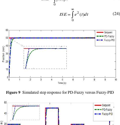
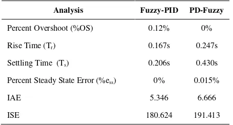
The step response for Fuzzy-PID Controller compared with PD-fuzzy controllers is shown in Figure 9. PD-Fuzzy has 0% overshoot which is better compared with Fuzzy-PID that has 0.12% overshoot. Both fuzzy-typed controllers have fast response which has less than 1 second settling time. This research also considered two performance indexes which are Integral Absolute Error (IAE) and Integral Squared Error (ISE) as in Equation (23) and Equation (24). Both Fuzzy-PID and PD-Fuzzy controllers exhibit quiet similar results for IAE and ISE. The proposed controllers have good ability of tracking the input as shown in Figure 10. Table 4 shows the summary of simulation analysis results.
dt t e
IAE
0 )
( (23)
dt t e ISE
0
2() (24)
Figure 9 Simulated step response for PD-Fuzzy versus Fuzzy-PID
Table 4 Comparison for step response position tracking between Fuzzy-PID and PD-Fuzzy analysis results-simulation
Analysis Fuzzy-PID PD-Fuzzy
Percent Overshoot (%OS) 0.12% 0%
Rise Time (Tr) 0.167s 0.247s
Settling Time (Ts) 0.206s 0.430s
Percent Steady State Error (%ess) 0% 0.015%
IAE 5.346 6.666
ISE 180.624 191.413
Then, the controllers are applied on the real servo-pneumatic actuator plant to control its position in real-time. NI PCI/PXI 6221 DAQ is used as a communication tool between the encoder, valves and the PC with two analog output channels for the valves and counter input channel for the encoder as discussed in The Servo-Pneumatic Actuator Plant section. The PWM output will be based on the control signal value, a positive control signal will cause opening the inlet valve and closing the outlet valve via the PWM and vice versa. Experimental data of position control for step response and multistep response tracking were done using both Fuzzy-typed controller at sampling time, ts = 0.001s. The advantage of select small sampling time is to minimize the effect of quantization of the input signal. Figure 11 shows the real-time position control for both controllers. The real-time results for both Fuzzy-typed controllers are almost similar especially in steady state error and rise time. The multistep response is design to suite for the proposed system which is the PABBS.
The servo-pneumatic actuator need to have fast and stable response to control the ball at the desired position. Fuzzy-PID and PD-Fuzzy shows compromised controls which have less settling time which are 0.5149s and 0.4509s. For overall response results, PD-Fuzzy proved to be better in terms of speed, accuracy and stability. In compare with Fuzzy-PID, its gives faster rise time however Fuzzy-PID controller is not stable as it had oscillation at every changing in setpoint as in Figure 11. In addition, PD-Fuzzy give less error compared with the other controllers where the value for Integral Squared Error (ISE) is 405.34. Table 5 shows the summary experimental analysis results for time, t=10s.
(a)
(b)
Figure 11 Response for real-time experiment (a) step response (b) multistep response
Table 5 Comparison for step response position tracking between Fuzzy-PID and PD-Fuzzy analysis results-experiment
Analysis Fuzzy-PID PD-Fuzzy
Percent Overshoot (%OS) 2.076% 0%
RiseTime (Tr) 0.3427s 0.3497
Settling Time (Ts) 0.5149s 0.4509s
Percent Steady State
Error (%ess) 0.28% 0.28%
IAE 12.72 13.13
ISE 441.3 405.34
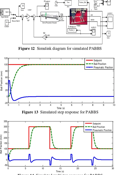
Figure 12 Simulink diagram for simulated PABBS
Figure 13 Simulated step response for PABBS
Figure 14 Simulated multistep response for PABBS
The position for the pneumatic actuator stroke, h is constraint to approximately ±50mm. This is because larger displacement of h will cause the ball to roll along the beam faster and more difficult to control. As in Figure 13 and Figure 14, the movement of the ball, x is correspond to the movement of the pneumatic actuator stroke, h where displacement of h = 0 when the ball is at equilibrium state. Table 6 shows the simulated analysis results for the PABBS that shows the controller design is compatible with the proposed system.
Table 6 Step response position tracking for PABBS analysis results - simulation
Analysis Position & Rate Feedback
Percent Overshoot (%OS) 0%
Rise Time (Tr) 0.9498s
Settling Time (Ts) 1.72s
Percent Steady State Error (%ess) 0.01%
5.0 CONCLUSION
The current research is devoted to study and design two different control strategies for servo-pneumatic actuator namely Fuzzy-PID controller and PD-Fuzzy controller with their implementation to the PABBS. The performance of position control of a
servo-pneumatic actuator using the designed controllers has been analysed. PD-Fuzzy controller offers better results in term of stability compared to Fuzzy-PID which is important in proposed PABBS system. To compare all controllers, the parameters for evaluating the response are identified. The most common method is by comparing the percentage overshoot (%OS), rise time (TR), settling time (TS), percent steady state error (%ess) and added with two performance index criteria which are Integral Absolute Error (IAE) and Integral Squared Error (ISE). The results obtained from the simulation and experiment of servo-pneumatic actuator showed that the designed controllers can be used for PABBS and simulation of the system proved that it can achieve to control the ball. The controller design for PABBS which is Feedback controller-PD-Fuzzy controller showed a compromise results and can be used for future work such as to improve the performance of other controllers and experiment of PABBS.
Acknowledgement
The authors would like to thank Universiti Teknologi Malaysia (UTM) and Ministry of Higher Education (MOHE) Malaysia under ERGS Grant No.Q.J130000.2523.04H90.
References
[1] Hazem I. Ali, Samsul Bahari B Mohd Noor, S. M. Bashi and M. H. Marhaban. 2009. A Review of Pneumatic Actuators (Modeling and Control). Australian Journal of Basic and Applied Science. 3 (2): 440–454. [2] G. K. I. Mann, H. Bao-Gang and R. G. Gosine. 1999. Analysis of Direct Action Fuzzy PID Controller Structures. IEEE Transactions on Systems, Man, and Cybernetics. Part B: Cybernetics. 29(3): 371–388.
[3] L. A. Zadeh (1973). Outline of a New Approach to the Analysis of Complex Systems and Decision Processes. IEEE Transactions on Systems, Man and Cybernetics. SMC-3(1): 28–44.
[4] E. H. Mamdani (1974). Application of Fuzzy Algorithms for Control of Simple Dynamic Plant. Proceedings of the Institution of Electrical Engineers. 121(12): 1585–1588.
[5] E. H. Mamdani and S. Assilian. 1975. An Experiment in Linguistic Synthesis with a Fuzzy Logic Controller. International Journal of Man-Machine Studies. 7(1): 1–13.
[6] T. Takagi and M. Sugeno. 1985. Fuzzy Identification of Systems and Its Applications to Modeling and Control. IEEE Transactions on Systems,
Man and Cybernetics. SMC-15(1): 116–132.
[7] M. Amjad, M. I. Kashif, S. S. Abdullah and Z. Shareef. 2010. Fuzzy Logic Control of Ball and Beam System. 2nd International Conference on
Education Technology and Computer (ICETC). 22-24 June 2010.
V3-489-V3-493
[8] Mohammad Keshmiri, Ali Fellah Jahromi, Abolfazl Mohebbi, M. H. A. and and W.-F. Xie. 2012. Modeling and Control of Ball and Beam System using Model Based and Non-Model Based Control Approaches. International Journal on Smart Sensing and Intelligent Systems. 5(1). [9] C. Wenzhuo, S. Xiaomei and X. Yonghui. 2012. Modeling and Modulation
of Nonlinear Ball-beam System Controller Based on Matlab. 9th International Conference on Fuzzy Systems and Knowledge Discovery
(FSKD). 29-31 May 2012. 2388–2391.
[10] A. A. M. Faudzi. 2010. Development of Intelligent Pneumatic Actuators and Their Applications to Physical Human-Mechine Interaction System. PhD. The Graduate School of Natural Science and Technology, Okayama University.
[11] K. Osman, A. A. M. Faudzi, M. F. Rahmat, N. D. Mustafa, M. A. Azman and K. Suzumori. 2012. System Identification Model for an Intelligent Pneumatic Actuator (IPA) System. IEEE/RSJ International Conference on Intelligent Robots and Systems (IROS). 7-12 Oct. 2012. 628–633. [12] S. Khan, S. F. Abdulazeez, L. W. Adetunji, A. H. M. Z. Alam, M. J. E.
Salami, S. A. Hameed, A. H. Abdalla and M. R. Islam. 2008. Design and Implementation of an Optimal Fuzzy Logic Controller Using Genetic Algorithm. Journal of Computer Science. 4 (10): 799–806.