ISSN 1991-8178
Corresponding Author:M.F. Rahmat, Department of Control and Instrumentation Engineering, Faculty of Electrical Engineering, Universiti Teknologi Malaysia, 81310 Skudai, Malaysia
Non-linear Modeling and Cascade Control of an Industrial Pneumatic Actuator
System
1
M.F. Rahmat,
2Sy Najib Sy Salim,
3Ahmad ‘Athif Mohd Faudzi,
3Zool Hilmi Ismail,
4S.I.
Samsudin,
1N.H.Sunar,
5K.Jusoff
1
Department of Control and Instrumentation Engineering, Faculty of Electrical Engineering,
Universiti Teknologi Malaysia, 81310 Skudai, Malaysia
2
Department of Control,Instrumentation and Automation Department, Faculty of Electrical
Engineering, Universiti Teknikal Malaysia Melaka, Hang Tuah Jaya, 76100 Durian Tunggal,
Melaka Malaysia
3
Department of Mechatronics and Robotics Engineering, Faculty of Electrical Engineering,
Universiti Teknologi Malaysia, 81310 Skudai, Malaysia
4
Department of Industrial Electronics, Faculty of Electrical and Electronics, Universiti Teknikal
Malaysia Melaka, Hang Tuah Jaya, 76100 Durian Tunggal, Melaka Malaysia
5
Department of Forest Production Faculty Universiti Putra Malaysia 43400 Serdang, Selangor,
Malaysia
Abstract: In this paper, a nonlinear mathematical modeling based on fundamental physical derivation is presented. The mass flow rate, pressure dynamic and equation of motion are derived referring to the previous research. Simulation work is done to confirm the model based on this derivation. Cascade control based on PID and P controller is designed through simulation in SIMULINK where the parameters of the controller are obtained through PID with optimization toolbox. The results reveal that both step and sinusoidal response test, the cascade controller consistently indicates outperform performance compared to classical PID method. In future, it is recommended to apply this technique to the real-time implementation.
Key words: Pneumatic servo system, mathematical modeling, positioning control, tracking control, cascade controller
INTRODUCTION
Pneumatic actuators are widely used in industrial robotics and automation, such as drilling, gripping, spraying and other applications. Due to their special advantages, e.g. low cost, high power-to-weight ratio, cleanliness and ease of maintenance, it has long been promoted as low cost alternatives to hydraulic and electric servo motor in automated materials handling tasks (Messina et al. 2005; Saleem et al. 2009a; Situm et al. 2004). In spite of these advantages, pneumatic actuators are subject to nonlinearities due to compressibility of air, valve fluid flow characteristics and sometimes higher than normal Coulomb friction which make accurate position control of a pneumatic actuator difficult to achieve (Wang et al. 1999). Due to the increasing demands of automation in industrial production lines around 1950s, the study on the pneumatic system was become vigorous. The first theoretical basis of the pneumatic system dynamic control was initially made by Prof. J. L. Shearer in 1956 (Shearer 1956) which the dynamic of the system was derived. In this research, a nonlinear differential equations as well as linear mathematic model of pneumatic double rod cylinder attached to a 4-way servo valve was developed and subsequently analyzed in detail. The nonlinear differential equations was theoretically derived based on energy conservation law, continuity equation, ideal gas state equation, mass flow rate and Newton’s second law. Whereas, to obtain the linear mathematical model, several assumptions were took into consideration by Shearer where the coulomb fiction and nonlinear static are neglected. Moreover, the piston position is about in mid-stroke position whilst the variation of the spool is assumed sufficiently small.
1960s, the researchers continued to work on the system model and controller design based on the classical control theory. For instance, Burrows (Burrows 1966; Burrows 1969) continued to work on this model to investigate the effect of the system for the different position and then provide the model for the whole stroke. It is interesting to note that, the system linear model was analyzed using root locus technique. The result indicates an improvement where the performance of the system operating in any other position is more stable compared to the earlier model. By using the same description model presented in (Burrows 1966; Shearer 1956) and (Burrows 1969), an approximate third order linear model was formulated by (Hamiti et al. 1996). In this research, the plant of the system was modified by adding an analogue feedback with proportional gain in which this gain is tuned until critically damped is obtained so that the third-order model transfer function can be considered as being composed of three first-order systems in series with some amount of dead time. (Sorli et al. 1999) introduced two different formulations (based on Matlab-Simulink environment and bond graph method) to model a pneumatic circuit that consists of double acting actuators connected to a directional 4-way digital valve. In this paper, the dynamics of the pneumatic actuator was described using equilibrium, continuity and energy equations according to the lumped parameters model of the system, whilst the friction force is assumed to be constant. The comparison for both simulation techniques shows a good agreement of the results.
In 1980s, Pulse-Width Modulation (PWM) driving technique was offered as an alternative to proportional control approach. Owing to the lack of a rigorous analytical approach based on the previous researches conducts by (Lai et al. 1992; Noritsugu 1985; Noritsugu 1986a; Noritsugu 1986b), Van Varseveld and Bone in (van Varseveld and Bone 1997) developed a discrete-time model of a PWM-controlled pneumatic servo system with an autoregressive system identification approach. Subsequently, Eric J. Barth at al in (Barth et al. 2002) proposed a method to transform the non-analytic description of PWM-based control into an analytic model via state-space averaging technique. These modeling results are suitable applied to the well-developed analytical control techniques such as sliding mode control. The improvement of electro-pneumatic fast switching on-off, which employ PWM driving technique, was reported in (Topcu et al. 2006). In this study, four of 2/2-way function valves were used to develop an inexpensive single stage solenoid valve to provide a fast switching time with considerably large amount of flow rates. The modeling of the system was produced based on four subsystems consist of electrical circuit, magnetic circuit, mechanical circuit and fluid circuit which derived by Kirchhoff’s law, magnetic force equation, Newton’s second law and standard equation for mass flow rate, respectively.
Regarding to the main purpose of the modeling is to design the controller, the proposed equations should be fit with on-line implementation. Due to this reason, an accurate model of a pneumatic actuator system with spool dynamics was reported by Richer E, Hurmuzlu (Richer and Hurmuzlu 2001). Here, the friction in piston seals, the difference in active areas of the piston, inactive volume, leakage between chambers, mass flow rate, time delay and Xow amplitude attenuation in valve-cylinder connecting tubes were considered. The validation of the model was attempted by comparing the experimental result with system identification and it leads a very good agreement between them. A methodology for deriving a nonlinear dynamic model for a pneumatic servo system has been presented by (Shu and Bone 2005). The accurate values for the model parameters were estimated through experiments. The experimental results proved that the parameter estimation for the valve model was unsuit with respect to the values stated in the datasheet. A. Saleem et al. employed a Mixed-Reality Environment (MRE) in order to identify the transfer function in real-time environment(Saleem et al. 2009b). The proposed method has been formed using a recursive least squares (RLS) algorithm based on the Auto-Regressive Moving-Average (ARMA) model. A case study has been conducted to validate the proposed methodology and developed platform. In their case study, a PID control with velocity feed-forward and feedback (PIDVF) controller was chosen and synthesised. The results indicate a reasonably good agreement between the simulation and real system behaviors.
In this paper, the nonlinear mathematical modeling and cascade control strategy based on PID and P controller for pneumatic servo system are presented. The basic idea is to maintain the PID as the main controller with a few modifications that could produce a significant impact on system performance. The nonlinear mathematical modelling of the pneumatic actuator system based on fundamental physical derivation is described in next section. It then continued by a brief description of the controller design. Meanwhile the simulation model which is represent the open loop and closed loop pneumatic positioning system is shown in the following discussion. Subsequently, the performances of the proposed controller based on positioning and tracking are described. Concluding remarks of the study are stated in the last section.
Modeling and Controller Design:
Nonlinear Model of the Pneumatic Actuator:
Physical systems for each mechanism need to be presented first in the form of mathematical equation before a certain analysis can be implemented towards those particular systems. The mathematical modeling is required before any control towards the systems can be explored. In general, modeling of any systems can be establish either from fundamental physical derivation or experimental data measured on the real system as shown in Figure 1.
In this paper, the nonlinear mathematical modelling based on fundamental physical derivation is presented. The mass flow rate, pressure dynamic and equation of motion are derived referring to the previous research. The mathematical model for dual action pneumatic actuators with proportional spool valves has been well described in the literature (G.Kothapalli and M.Y. Hassan 2008; Hildebrandt et al. 2010; Richer and Hurmuzlu 2001; Vladislav Blagojević 2007; Željko Šitum 2005).
Fig. 1: Mathematical model from physical systems
The compressible mass flow rate, through a valve orifice can be described as (Richer and Hurmuzlu 2001):m
(1) 1
( , ) 1 1
1 2
m
P
Pu d
Cf Av C if Pcr
P
T u
P Pu k
d
k k
P P P
Pu d d d
C Av C if Pcr
f T P P P
u u u
where,
- upstream and downstream pressureP Pu, d - Mass flow rate m P P
u, d
Cf - nondimensional discharge Av - effective area of the valve orifice
T - temperature
k - specific heat ratio
The effective area, AV of the valve orifice can be expressed in many approaches. Here, the approach describes by (G.Kothapalli and M.Y. Hassan 2008) was considered in which the relationship between the effective area and the control spool movement can be expressed as:
(2)
2
4
V spool
A
X
and the relationship between control spool movement and the voltage input is:
(3) spool V
X C u
where,
Xspool - spool displacement CV - valve constant u - voltage input
Next, the constants C1 and C2 are given by;
(4) 1 1 1 2 1 k k k C R k
(5) 2 2 1 k C R k
whereas Pcr is a critical pressure regarding to the ratio between downstream pressure Pd and upstream pressure Pu. The value of Pcr can be determined can be expressed as,
(6) 1 2 1 k k Pcr k
Owing to the assumption of there is no change in the total heat energy of the gas under compression, the specific heat ratio for air is k=1.4. According to Peter Beater, 2007(Beater 2007), by referring to the standard ISO 6358, with a relative humidity of 65%, the value of gas constant R, temperature T, and ambient pressure Po are 288 J/(kg.K), 293.15 K and 100 kPa, respectively. Consequently the constant C1 and C2 are found to be 0.040418 and 0.156174 which the values are obtained using equation (3). Subsequently, by using equation (4) the critical pressure ratio, Pcr is found to be 0.528.
The upstream and downstream pressures are different for the charging and discharging process of the cylinder chamber according to the following functions:
(7)
,
mA m S A i P P
(8)
,
mA m A ao P P
(9)
,
mB m S B i P P
(10)
,
mB m B ao P P
where,
- mass flow rate into cylinder chamber A and B respectively.mA andmB
i i
- mass flow rate leave from cylinder chamber A and B respectively.mA andmB
o o
PA and PB - pressure inside Chamber A and B respectively. PS - supply pressure
Pa - ambient pressure
Equation (7) and (9) represent the charging process where the pressure in the supply tank is considered to be upstream and the pressure in the cylinder chamber is the downstream. Whereas, for discharging process as represented in equation (8) and (10), the pressure in the chamber is the upstream and the ambient pressure is the downstream pressure. The status of the flow can be classified either choked flow or under-chocked flow depending on the downstream pressure Pdand the upstream pressure Puof the orifice. The status of the flow is regard as a choked flow when Pd/Pu is less than the critical pressure ratio Pcr.
With the assumption that the gas is perfect and the process is considered to be adiabatic, the rate of change for the pressure inside a pneumatic chamber can expressed as:
(11)
. .
i o
R T k
P
P
m
m
k
V
V
V
where,
P - pressure inside chamber
- rate of change in pressure inside chamber
P
- inlet mass flow rate to chamberm
i
- outlet mass flow rate from chambermo
V - volume of each chamber
- rate of change in volume of each chamber
V
The origin of the piston placement can be chosen either from the one sides at the end of the stroke or at the middle of the stroke. By choosing the origin on the one side at the end of the stroke, the volume of chamber 1 and 2 can be expressed as:
(12)
1
.
V
A x
(13)
2 .
V A Lx
Subsequently, by differentiate both equations (12) and (13), the rate of change in volume of each chamber can be obtained as:
(14)
1 .
V A x
(15)
2
.
V
A x
(16) 1 1 1 . . . . . .
mi mo x
O O
R T k P
P k A
A x V A x V
(17)
2 2 2. .
.
.
.
.
mi mo x
V V
O O
R T k
P
P
k
A
A
L
x
A
L
x
where,x - piston position
- rate of change of piston’s position
x
L - piston stroke
Voi - inactive volume at the end of stroke and admission port
The equation of motion for piston rod including the mass and friction effects of pneumatic cylinder can be expressed using Newton’s second law as:
(13)
M
LM
P
x F
fF
LP A
A AP A
B BP A
a r
where,
ML - external load mass MP - piston rod mass Ff - friction force FL - external force
Ar - rod cross sectional area Pa - atmospheric pressure
The LuGre friction model proposed by (C. Canudas de Wit et al. 1995) is considered in this study. The friction force (Ff), dynamics of the internal state (z) and stribeck effect function g(v) are given in equation (14), (15) and (16), respectively. Through these equations, the relationship between velocity and friction force for the steady-state of motion can be derived as equation (17):
(14)
0 1
f
F
z
z Bv
(15) 0
( )
v
z v z
g v
(16) 2 0(
).
( )
s v vC S C
F
F
F
e
g v
(17) 20
( ) sgn( )
.
sgn( ) (
).
ssgn( )
.
f
v v
C S C
F
g v
v
B v
F
v
F
F
e
v
B v
where,- damping coefficient
1
B - viscous friction Fc - Coulomb friction Fs - static friction Cascade Controller:
A control strategy involves in this research has been designed based on Proportional Integral Derivative (PID) controller. The classical PID controller emphasizes a straight forward design procedure in order to achieve the favourable result in controlling the position and continuing motion as the ultimate goal. However, as position control performance more rigorous, this type of controller is often difficult to gives the good performance due to the presence of nonlinearities especially in pneumatic systems. In order to overcome this problem, many control strategies have been investigated by researchers such as sliding mode control, robust control, adaptive control, fuzzy logic control and others. In this paper, the cascade controller has been proposed because of several practical advantages.
In this strategy, the simulation model is used to tune inner velocity loop controller as well as the outer position loop controller. According to the previous paper reported by (Mostafa Taghizadeh 2009), it was proved that the velocity feedback is capable to give the good effect on tracking of sinusoidal input. (Kamarudin and Md.Rozali 2008; Sy Najib Sy Salim et al. 2009) provides procedure for cascade control tuning method where it mentions that for any multi-loop control scheme, the dynamics of all loop need to be taken into account while designing a controller. For this system, a Proportional (P) controller is employed to control the velocity while the PID controller is engaged in order to controller the position of the cylinder piston. The PID controller for the outer loop is optimized to reduce the tracking error by means of Simulink optimization toolbox. The back calculation anti-windup feature is included in the position loop PID controller to prevent the integrator in the controller accumulating excessive output values when load is applied because it results in significant sustained position errors. In general, the mathematical equation of P and PID controller are given by equations (18) and (19), respectively.
(18)
( )
p p
u
K e t
(19)
( )
p t( )
( )
PID p p d
K
d
u
K e t
e
K T
e t
T
dt
RESULTS AND DISCUSSION
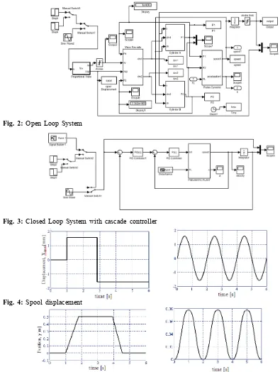
The simulation of open-loop and closed loop pneumatic positioning system is simulated using MATLAB/SIMULINK as shown in Fig. 2 and Fig. 3, respectively. In order to simulate the model, the actuator model consists of a pneumatic rod cylinder with stroke length L=500 mm and diameter d=15mm are considered. The temperature T, ambient pressure Pa, specific heat ratio, k and gas constant, R are based on standard ISO 6358. The source pressure Ps, maximum effective area of valve Av, coefficient discharge Cf and
valve constant Cv are and respectively. In addition, the payload with 2.5kg
5 6
5 10 Pa, 7.83 10 3.158 10 4
,
is applied in the simulation. Figure 2 shows the block diagram of the nonlinear mathematical model of the servo pneumatic system based on the equations describes previously. There are two reference inputs applied to verify the simulation model namely step signal and sinusoidal signal.
In this section, the positioning and tracking performance of the open loop and closed loop pneumatic actuator system are considered. Numerical simulations have been performed in order to investigate the performance of the proposed cascade controller.
Open Loop Simulation:
Fig. 2: Open Loop System
Fig. 3: Closed Loop System with cascade controller
Fig. 4: Spool displacement
Fig. 5: Output response for piston position
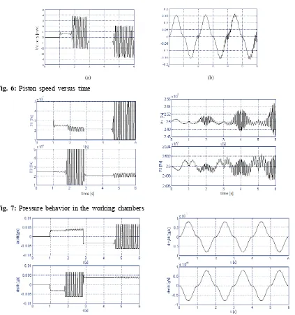
Fig. 6: Piston speed versus time
Fig. 7: Pressure behavior in the working chambers
Fig. 8: Mass flow rate as a function of time
Closed Loop Simulation:
In this section, a classical PID controller and cascade controller are employed to the system in order to compare the performance of both cases. The controller gains are given in Table 1. Fig. 9a and Fig. 9b show the closed loop responses of the system simulation based on cascade controller and classical PID controller, respectively. Based on the response obtained, it can be observed that the performance of the cascade controller was performed better compared to the response obtained through classical PID controller. The steady state response of the system with cascade controller shows the good agreement to the set point where the piston of cylinder can reach the target in less than 1.5s with steady state error less than 0.05mm.
Table 1: Control parameters
Parameters Controller (Speed) Controller (Position)
Kp 10 126.82
Ki - 99.24
Fig. 9: Positioning performance comparison between the; (a) cascade PID/P controller and (b) Classical PID controller
Table 2 lists the performance measures; rise time (tr), settling time (ts) and percentage of overshoot (%OS)
based on both cascade controller and classical PID controller technique. As can be seen from table 2, the steady state error and percentage overshoot of the system with cascaded controller reduced significantly compared to classical PID controller. Besides, it is obvious that, the output response for system with classical PID controller was unsuccessful to defeat the oscillation. This result shows that the method proposed is valuable and still easy to put into practice.
Table 2: Performance of the cascade controller and the classical PID controller
Mass (Kg) Performance index Cascade Controller Classical PID Controller
Rise time, tr (s) 0.280 0.230
2.5 Settling time, ts (s) 1.270 12.120
Overshoot (%) 7.801 35.501
Steady state error, ess (mm) 0.029 5.002
Rise time, tr (s) 0.290 0.210
5 Settling time, ts (s) 1.302 9.350
Overshoot (%) 8.670 35.301
Steady state error , ess (mm) 0.033 5.030
Rise time, tr (s) 0.290 0.191
8 Settling time, ts (s) 1.204 5.610
Overshoot (%) 7.806 35.404
Steady state error, ess (mm) 0.039 8.210
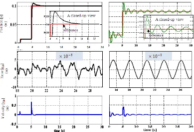
For tracking motion, sinusoidal reference input with amplitude 0.1 and frequency 0.5Hz are applied to the system. Fig. 10 and Fig. 11 illustrate the tracking performance of the system simulation based on classical PID controller and cascade controller, respectively. Obviously, the result obtained with cascade controller is in good agreement with the reference input as compared to the classical PID controller. As illustrated in Figure 11, it can be seen that the tracking error is about 1%. It was contrast to the system with classical PID controller in which it fails to retain a good performance.
frequency. In addition, this can be seen clearly through the closed-up view in which the system that controlled by the proposed method manage to track the input signal in a short period of time when the frequency changes. Conversely, for the system with classical PID controller it fails to track the input signal when the same situation occurs. In addition, the Root Mean Square Error (RMSE) values for both types of controller with certain frequencies and loads are listed in Table 3. It can be noticed that the steady-state error for the system with classical PID controller is worst compared to cascade controller. The RMSE values are calculated using the following equation:
(16) 2
0
1
TRMSE
e dt
T
Fig. 10: Tracking performance for the system with classical PID Controller
Fig. 11: Tracking performance for the system with cascade Controller
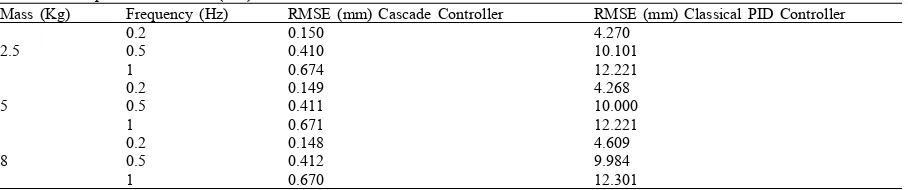
Table 3: Comparison of RMSE (mm) values for horizontal moves
Mass (Kg) Frequency (Hz) RMSE (mm) Cascade Controller RMSE (mm) Classical PID Controller
0.2 0.150 4.270
2.5 0.5 0.410 10.101
1 0.674 12.221
0.2 0.149 4.268
5 0.5 0.411 10.000
1 0.671 12.221
0.2 0.148 4.609
8 0.5 0.412 9.984
1 0.670 12.301
Conclusion:
In this paper, the mathematical modeling of a pneumatic servo system based on fundamental physical derivation was review and derived. The equations of compressible mass flow rate, through a valve orifice, pressure dynamic P1 and P2 as well as motion are described in details. The simulation of the model was
demonstrated using MATLAB/SIMULINK and the results of open-loop system were presented to confirm the model based on this derivation. The proposed cascade controller which is involves combination of PID and P controller was applied to the system. The simulated results are furnished to reveal the effectiveness of the proposed cascade controller including positioning and tracking control. The results prove that, the cascade controller exhibits the high performance in both positioning and tracking as compared to the classical PID controller. According to the simulation results, the proposed controller is suitable and applicable for real-time implementation.
ACKNOWLEDGMENT
The authors would like to thank Universiti Teknologi Malaysia (UTM), Universiti Teknikal Malaysia Melaka (UTeM) and Ministry of Higher Education (MOHE) for their support.
REFERENCES
Ali, H.I., S.B.B.M. Noor, S.M. Bashi and M.H. Marhaban, 2009. "A Review of Pneumatic Actuators (Modeling and Control)." Australian Journal of Basic and Applied Sciences, 3(2): 440-454.
Barth, E.J., J. Zhang and M. Goldfarb, 2002. "Sliding Mode Approach to the PWM-Controlled Pneumatic Systems." Presented at Proceedings of the American Control Conference Anchorage, 2362-2367.
Beater, P., 2007. Pneumatic Drives (System Design, Modeling and Control),. Verlag Berlin Heidelberg: Springer.
Burrows, C.R., 1966. "Use of Root loci in design of pneumatic Servo-Motors." Control., 423-427. Burrows, C.R., 1969. "Effect of Position of the stability of Pneumatic Servomechanisms." Journal Mechanical Engineering Science, 11(6): 615-616.
Canudas, C. de A. Wit, H. IEEE, S.M. Olsson, K.J. IEEE, F. htrom, IEEE and P. Lischinsky, 1995. "A New Model for Control of Systems with Friction." IEEE Transactions on Automatic Control, 40(3): 419-425. Cheah, C.C., S. Kawamura and S. Arimoto, 1998. "Feedback control for robotic manipulator with uncertain kinematics and dynamics." Presented at Proceedings of IEEE International Conference on Robotics and Automation. Leuven, Belgium: IEEE, 3607-3612.
Friedland, B. and Y.J. Park, 1992. "On adaptive friction compensation." Automatic Control, IEEE Transactions on, 37(10): 1609-1612.
Kothapalli, G. and M.Y. Hassan, M. I. 2008. "Design of a Neural Network Based Intelligent PI Controller for a Pneumatic System." IAENG International Journal of Computer Science, 35(2).
Hamiti, K., A. Voda-Besancon and H. Roux-Buisson, 1996. "Position Control of a Pneumatic Actuator under the Influence of Stiction." Control Eng. Practice, 4(8): 1079-1088.
Hildebrandt, A., R. Neumann and O. Sawodny, 2010. "Optimal System Design of SISO-Servopneumatic Positioning Drives." Control Systems Technology, IEEE Transactions on, 18(1): 35-44.
Kamarudin, M.N. and S. Md. Rozali, 2008. "Simulink Implementation of Digital Cascade Control DC Motor Model - A didactic approach." Presented at 2nd IEEE International Conference on Power and Energy (PECon 08), Johor Baharu, Malaysia, pp: 1043-1048.
Messina, A., N.I. Giannoccaro and A. Gentile, 2005. "Experimenting and modelling the dynamics of pneumatic actuators controlled by the pulse width modulation (PWM) technique." Mechatronics, 15(7): 859-881.
Mostafa Taghizadeh, A.G. a. F.N. 2009. "Improving dynamic performances of PWM-driven servo-pneumatic systems via a novel servo-pneumatic circuit." ISA Transactions, 48: 512-518.
Noritsugu, T., 1985. "Pulse-Width Modulated Feedback Force Control of a Pneumatically Powered Robot Hand." Presented at Proc. Of International Symposium of Fluid Control and Measurement, Tokyo, 47-52.
Noritsugu, T., 1986a. "Development of PWM Mode Electro- Pneumatic Servomechanism. Part I: Speed Control of a Pneumatic Cylinder." Journal of Fluid Control, 17(1): 65-80.
Noritsugu, T., 1986b. "Development of PWM Mode Electro-Pneumatic Servomechanism. Part 11: Position Control of a Pneumatic Cylinder." Journal of Fluid Control, 17(2): 7-31.
Richer, E. and Y. Hurmuzlu, 2001. "A High Performance Pneumatic Force Actuator System Part 1 -Nonlinear Mathematical Model." ASME Journal of Dynamic Systems Measurement and Control, 122(3): 416-425.
Saleem, A., S. Abdrabbo and T. Tutunji, 2009a. "On-line identification and control of pneumatic servo drives via a mixed-reality environment." The International Journal of Advanced Manufacturing Technology, 40(5): 518-530.
Saleem, A., C.B. Wong, J. Pua and P.R. Moore, 2009b. "Mixed-reality environment for frictional parameters identification in servo-pneumatic system." Simulation Modelling Practice and Theory, 17(10): 1575-1586.
Shearer, J.L., 1956. "Study of Pneumatic Process in the Continuous Control of Motion With Compressed Air." Transactions of the ASME, 233-249.
Shu, N., and G.M. Bone, 2005. "Development of a nonlinear dynamic model for a servo pneumatic positioning system." Presented at International conference on Mechatronics and Automation, Niagara Falls, Canada 43-48.
Situm, Z., D. Pavkovic and B. Novakovic, 2004. "Servo Pneumatic Position Control Using Fuzzy PID Gain Scheduling." ASME Journal Of Dynamic Systems, Measurement and Control, 126(2): 376 - 387.
song, J., and Y. Ishida, 1997. "A robust sliding mode control for pneumatic servo systems." Int. J. Engng Sci., 35(8): 711-723.
Sorli, M., L. Gastaldi, E. Codina and de S. las Heras, 1999. "Dynamic analysis of pneumatic actuators." Simulation Practice and Theory, 7(5-6): 589-602.
Sy Najib Sy Salim, Hoo, E.C.S., S.M. Rozali, H. Jamaluddin and M.K. Aripin, 2009. "Cascade PI Control of an Inverted Pendulum using C# with Knowledge Base." Presented at Proceedings of MUCEET2009 Malaysian Technical Universities Conference on Engineering and Technology, MS Garden,Kuantan, Pahang, Malaysia, 528-532.
Topcu, E.E., I. Yuksel and Z. Kamis, 2006. "Development of electro-pneumatic fast switching valve and investigation of its charcteristics." Mechatronics, 16: 365-378.
van Varseveld, R.B. and G.M. Bone, 1997. "Accurate position control of a pneumatic actuator using on/off solenoid valves." Mechatronics, IEEE/ASME Transactions on, 2(3): 195-204.
Vladislav Blagojević, M.S., 2007. "Mathematical and Simulink Model of the Pneumatic System with Bridging of the Dual Action Cylinder Chambers." FACTA UNIVERSITATIS Series: Mechanical Engineering, 5(1): 23-31.
Wang, J., J. Pu and P. Moore, 1999. "A practical control strategy for servo-pneumatic systems." Control Engineering Practice. 7(12): 1483-1488.