ISSN: 1693-6930
accredited by DGHE (DIKTI), Decree No: 51/Dikti/Kep/2010 203
Adaptive-Fuzzy Controller Based Shunt Active Filter for
Power Line Conditioners
Karuppanan PitchaiVijaya*, KamalaKanta Mahapatra National Institute of Technology-Rourkela
India-769008, Telp 91-661-2476773, Fax 91-661-2462999 e-mail: [email protected]*, [email protected]
Abstrak
Makalah ini menghadirkan pengendali logika fuzi (FLC) baru dengan tapis aktif shunt berbasis kalang terkunci fasa (PLL) untuk pengkondisi saluran listrik (PLCs) guna meningkatkan kualitas daya pada sistem distribusi. Tapis aktif ini diimplementasikan dengan inverter sumber tegangan (VSI) terkendali arus untuk mengkompensasi harmonik arus dan daya reaktif pada titik kopling bersama. Pulsa penyaklaran pengendali gerbang VSI berasal dari pengendali arus histeresis (HCC) fuzi adaptif dan metode ini menghitung lebar bidang histeresis secara efektif menggunakan logika fuzi. Lebar bidang ini dapat diatur berdasarkan kompensasi variasi arus, yang digunakan untuk mengoptimalkan frekuensi penyaklaran yang diperlukan dan memperbaiki tapis aktif secara substansi. Sisteem tapis daya aktif shunt ini diinvestigasi dan diverifikasi pada keadaan tunak dan transien pada kondisi beban tak linear. Tapis aktif shunt ini telah memenuhi standar harmonik yang direkomendasikan IEEE 519 and IEC 61000-3.
Kata kunci: tapis daya aktif, fuzi adaptif, pengendali arus, pengkondisi jaringan daya listrik, kualitas daya
Abstract
This paper presents a novel Fuzzy Logic Controller (FLC) in conjunction with Phase Locked Loop (PLL) based shunt active filter for Power Line Conditioners (PLCs) to improve the power quality in the distribution system. The active filter is implemented with current controlled Voltage Source Inverter (VSI) for compensating current harmonics and reactive power at the point of common coupling. The VSI gate control switching pulses are derived from proposed Adaptive-Fuzzy-Hysteresis Current Controller (HCC) and this method calculates the hysteresis bandwidth effectively using fuzzy logic. The bandwidth can be adjusted based on compensation current variation, which is used to optimize the required switching frequency and improves active filter substantially. These shunt active power filter system is investigated and verified under steady and transient-state with non-linear load conditions. This shunt active filter is in compliance with IEEE 519 and IEC 61000-3 recommended harmonic standards.
Keywords: active power filter, adaptive-fuzzy, current controller, power line conditioners, power quality
1. Introduction
The effectiveness of active power filter depends on the design and characteristics of current controller [9]. There are various PWM-current control strategies proposed for active filter [10]. The hysteresis current controller has the highest rating among other control methods such as sinusoidal-PWM and triangular-current controller in terms of quick current controllability and easy implementation [9-10]. The advantages of fixed-HCC are simple design and unconditioned stability [11]. However, this control scheme exhibits several demerits, such as uneven switching frequency, possible to generate resonances and difficult to design the passive filter system. This unpredictable switching function affects the active filter efficiency and reliability [12]. Adaptive-hysteresis current controller overcomes these fixed-HCC demerits [13-14]. But adaptive-HCC is having more switching power losses due to high frequency and this problem is addressed by proposed adaptive-fuzzy-HCC. The Adaptive-Fuzzy HCC calculates the hysteresis bandwidth effectively with the help of fuzzy logic and reduces the switching power losses [15].
This paper presents a fuzzy logic along with PLL-synchronization controller based shunt active power filter for enhancing the power quality. The PLL can operate satisfactorily even under distorted and unbalanced system voltages. The shunts active current controlled voltage source inverter switching pulses are generated from proposed adaptive-fuzzy-hysteresis current controller. These shunt active power filter is validated and investigated under steady and transient-state conditions.
2. Research Method
The proposed control system consists of two parts: (1) reference current extractor using PLL synchronization with fuzzy logic controller, and (2) voltage source inverter switching control method using adaptive-fuzzy-hysteresis current controller.
2.1 Reference Current Extractor
The reference current is extracted from distorted line-current using PLL along with fuzzy logic controller. This control algorithm is based on sensing source voltage and current only (No need to sense load currents and compensation currents) that is reduced sensors and complexity.
2.1.1 PLL Synchronization
The phase locked loop circuit is meant for operation under distorted and unbalanced voltages [1], [3]. This algorithm is based on the three-phase instantaneous active power expression p3φ =vaia +vbib+vcic. The feedback signals ia(ωt)=sin(ωt) and
) 3 / 2 sin( )
(ωt = ωt+ π
ic is built up on PLL-circuit and time integral ω is calculated using proportional-integral gains. The PLL-circuit can reach a stable point when the input p3φ of the proportional-integral -controller has a zero average value (p3φ =0) and has minimized
low-frequency oscillating portions in three-phase voltages. Once the circuit is stabilized, the average value of p3φ is zero and the phase angle of the supply voltage is at fundamental frequency. At this condition, the currents become orthogonal to the fundamental phase voltage component. The PLL synchronizing output templates are
݈݈ = sin (߱ݐ) (1)
݈݈ = sin (߱ݐ− 2ߨ/3) (2)
݈݈ = sin (߱ݐ+ 2ߨ/3) (3)
The PLL output is multiplied with fuzzy logic controller output (peak currentImax) to determine the required reference current.
2.1.2 Fuzzy Logic Controller
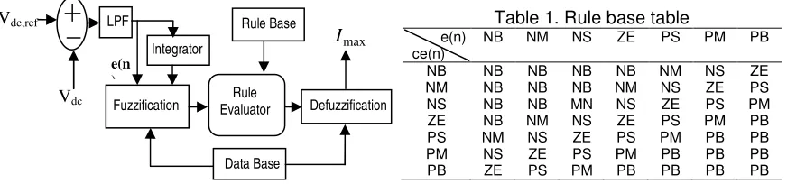
logic control algorithm of an active power filter in a closed loop, the dc-bus capacitor voltage is sensed and then compared with the reference value. The compared error signal
(
e=VDC,ref −VDC)
allows only the fundamental component using the Butterworth 50 Hz LowPass Filter (LPF). The error signale(n)and integration of error signal or change of error signal
) (n
ce are used as inputs for fuzzy processing as shown in Figure 1.
The output of the fuzzy logic controller limits the magnitude of peak reference current
max
I . The fuzzy logic controller characterized by: (1) seven fuzzy sets (NB, NM, NS, ZE, PS, PM, PB) for each input and output variables, (2) triangular membership function is used for the simplicity, (3) implication using mamdani-type min-operator, and (4) defuzzification using the height method.
Fuzzification: Fuzzy logic uses linguistic variables instead of numerical variables. In a control system, error between reference signal and output signal can be assigned as Negative Big (NB), Negative Medium (NM), Negative Small (NS), Zero (ZE), Positive Small (PS), Positive Medium (PM), Positive Big (PB). The process of fuzzification includes numerical variable (real number) convertion to a linguistic variable (fuzzy number).
Rule Elevator: Conventional controllers like PI and PID have control gains which are combination of numerical values. In case of fuzzy logic controller, it uses linguistic variables, instead of numerical. The basic fuzzy logic controller operation required for evaluation of fuzzy set rules areAND(∩), OR
( )
∪ and NOT(−)for intersection, union and complement functions respectively, it is derived asAND-Intersection : µA∩B=min[µA(X),µB(x)] OR-Union : µA∪B=max[µA(X),µB(x)] NOT-Complement : µA=1−µA(x)
Defuzzification: The rule of fuzzy logic generation requires output in a linguistic variable, according to real world requirements; linguistic variables have to be transformed to crisp output (Real number). This selection of strategy is compromisd between accuracy and computational intensity.
Database: The database stores the definition of the triangular membership function required by fuzzifier and defuzzifier.
Rule Base: The rule base stores the linguistic control rules required by rule evaluator (decision making logic). The 49-rules used in this proposed controller are shown in Table 1. The output of the fuzzy controller estimates the magnitude of peak reference currentImax. This current Imax takes response of the active power demand of the non-linear load for harmonics and reactive power compensation. The peak current multiplied with PLL output to determine the required reference current.
Figure 1. Fuzzy logic controller
Table 1. Rule base table
e(n) ce(n)
NB NM NS ZE PS PM PB
NB NB NB NB NB NM NS ZE
NM NB NB NB NM NS ZE PS
NS NB NB MN NS ZE PS PM
ZE NB NM NS ZE PS PM PB
PS NM NS ZE PS PM PB PB
PM NS ZE PS PM PB PB PB
PB ZE PS PM PB PB PB PB
e(n )
Defuzzification Rule Base
Fuzzification Evaluator Rule
max I
Vdc Vdc,ref LPF
Integrator
2.2 Adaptive-Fuzzy Hysteresis Current Controllers
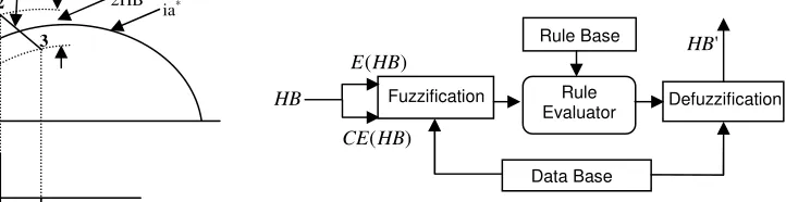
The fixed-hysteresis current controller has unpredictable switching functions and affects the active filter efficiency and reliability. The adaptive-hysteresis current controller overcomes the fixed-HCC demerits. But adaptive-HCC has more switching power losses due to high frequency and this problem is addressed by proposed adaptive-fuzzy HCC. It calculates the hysteresis-bandwidth with the help of fuzzy logic and reduces the switching power losses. Figure 2 shows the PWM-voltage source inverter current and voltage waves for phasea. The currentia tends to cross the lower hysteresis band at point 1, where the switch S1 is ON.
The linearly rising current (ia+) then touches the upper band at point 2, where the switch S4 is switched ON. The linearly falling current (ia−) then touches the lower band at point 3. The following equations can be written in the switching intervalst1and t2 [12-13]
1
From the geometry of Figure 2, we can write
*
Adding (6)and(7)and substituting(8) we can write
*
Substituting(5)in(9),and simplifying,
*
Substituting(12)in(11),it gives,
Here, m=dia*/dt is the slope of reference current signals. From this equation (13), the hysteresis bandwidth HB is derived from the modulation frequencyfc , supply voltageVs,
dc-side capacitor voltageVdc, slope of the reference current signalsdia*/dt and decoupling inductanceL of the active power filter. This adaptive-hysteresis bandwidth HBas an error signal E(HB) and change of error signal CE(HB) are used as inputs for fuzzy processing. The adaptive-fuzzy-hysteresis band HB'is the output of fuzzy controller that is shown in Figure 3. The fuzzy logic rule base stores the linguistic control rules required by rule evaluator. The 49-rules used in this controller as shown in Table 1.
Figure 2. Adaptive hysteresis current controllers
Figure 3. Fuzzy logic controllers
The output of fuzzy logic controller HB'(hysteresis bandwidth) can be modulated at different points of the fundamental frequency cycle to control the switching pattern of the voltage source inverter. The calculated hysteresis bandwidth HB'is applied to the variable HCC. The variable HCC is created by s-functions in Matlab to produce gate control switching pulses and these pulses will drive the inverter. For symmetrical operation of all three-phases, the hysteresis bandwidth HB'is denoted as HB'a,HB'b andHB'c of same value, but having 1200 phase difference. The adaptive-fuzzy-HCC based bandwidth HB' should maintain the modulation frequency constant. This controller reduces the switching power losses and improves the PWM performances for active power filter substantially.
3. Results and Discussion
The performance of the proposed adaptive-fuzzy-HCC method is evaluated through Matlab/Simulink power tools. The model system consists of a three-phase distorted supply voltage with a rectifier R-L load.The shunt active filter is connected in the distribution grid at PCC through filter inductance and operates in a closed loop. The three-phase active power filter comprises of six-power transistor with diodes, a dc-bus capacitor, RL-filter, compensation controller (PLL-circuit with FLC) and switching signal generator (adaptive-fuzzy-HCC) as shown in the Figure 4. The system parameters values are; Line to line source voltage is 440 V; System frequency (f) is 50 Hz; Source impedance of RS, LS is 1 Ω; 0.1 mH; Filter impedance of Rc, Lc is
1 Ω; 1 mH respectively; Diode rectifier RL, LL load: 20 Ω; 100 mH respectively; DC-side
capacitance (CDC) is 1200 µF; Reference voltage (VDC, ref) is 400 V; Power devices build by
MOSFETs with freewheeling diodes.
Case1 Steady state
The system is tested under distorted supply voltages. The Figure 5 (a) indicates three-phase distorted source voltage. The PLL-circuit is used to synchronize the distorted voltages and generates balanced (regulated) instantaneous sinusoidal voltages plla,pllb,pllc that are shown in Figure 5(b).
HB Fuzzification Defuzzification
Rule Base
Rule Evaluator
Data Base
' HB )
(HB E
) (HB CE
-0.5Vdc +0.5Vdc
t1 t2
S1
S4 1
2
3 ia
-ia+ 2HB
Fig
(a)
(c)
(e)
(g)
Figure 5. Simulation result; (c) Load current, (d) Referen power facto
These PLL outputs are distorted/unbalanced source
Vsa,Vsb,Vsc 3-phase supply
PLL Synch Techn
Voltage Sensor
Figure 4. Shunt active power filter system
(b)
(d)
(f)
(h)
(a) distorted source voltage, (b) PLL-synchroniza ence current, (e) Compensation current, (f) source c ctor waveforms, and (h) DC-side capacitor voltage
in phase with the fundamental compone e voltages. The source draws non-sinusoidal or
isa*,isb*,isc*
PWM-VSI
isa,isb,isc
ica,icb,icc
Rs,Ls PCC
Reference current generator
Vdc Sensor CDC
iLa, iLb, iLc
Non-sinusoidal L
chronization chnique
Adaptive-Fuzzy HCC
Fuzzy Logic Controller
ge Current
Sensor
Vdc, ref 3
ization waveform, e current, (g) unity
nent of the the r harmonic current
RL
LL
due to the non-linear chara compensating the harmonics rectifier load current or sour desired reference current is synchronization with fuzzy compensating current that is presented in Figure 5 (f) that i but opposite current harmonic improves power factor as show DC-side capacitance voltage the ripple to certain level and Figure 5 (h).
Case 2 Transient state For transient, the stea at T=0.08-0.14/0.2s. Similar w source current after compen becomes sinusoidal. The load non-linear characteristics tha particular phase (phase a). Ot The Fast Fourier Tran fundamental frequency at 50 plotted under non-linear load c is measured under non-linea APF system. This result indic improves the power quality i (THD) measured from source compensator active filter mad compared as given in Table load conditions. The obtaine
Steady state Transient t indicates the current is sinusoidal. It is achieved nic components at PCC. APF is suppressing the re
own in Figure 5 (g), phase (a) voltage and current is controlled by fuzzy logic controller (FLC). This c nd makes settling time to a low value (t= 0.076s) a
teady state suddenly changes to transient conditio r waveforms are obtained and verified in transien ensation is presented in Figure 6 (a) that indic ad current contains harmonics and fundamental co that are shown in Figure 6 (b). These current
Other phases are not shown as they are only phase ransform (FFT) is used to measures the order of ha 0 Hz of the source current. The magnitudes of th d condition without/with APF and are shown in Figu
(b)
ulation result (a) source current and (b) load curre
(b)
nics (a) non-linear load condition; the source curren THD=26.67%), (b) with APF (THD=2.04%)
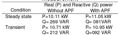
eactive (Q) power is calculated and given in the Ta ear load condition using adaptive-fuzzy-hysteresis
icates the active power filter is suppressing the re y in the distribution system at PCC. The total ha ce current on the ac main network. The adaptive-ade sinusoidal source current in the supply. THD e 3. The simulation is done distorted supply voltag ined results proof that source current and load
Steady state Steady state Transient
variation in steady state and transient conditions. FFT analysis of the active filter brings the THD of the source current into compliance with IEEE and IEC standards harmonic.
Table 2. Real (P) and Reactive (Q) power measurement
Condition
Real (P) and Reactive (Q) power
Without APF With APF
Steady state P=10.11 kW Q= 269 VAR
P=11.05 kW Q= 081VAR Transient P= 10.71 kW
Q= 212 VAR
P= 10.95 kW Q=092 VAR
Table 3. FFT analysis of Total harmonic distortion (THD)
Condition(THD) without APF with APF
Steady state 26.67 % 2.04 %
Transient 26.33 % 2.45 %
Power factor 0.9677 0.9999
5. Conclusion
The investigation demonstrates a fuzzy logic controller in conjunction with the PLL-synchronizing circuit active power filter. The FLC ensures that the dc-side capacitor voltage is nearly constant with small ripple besides extracting fundamental reference currents. The PLL-circuit assists the APF to function even under distorted/unbalanced voltage conditions. The shunt APF is implemented with current controlled voltage source inverter and is connected at PCC for compensating the current harmonics and reactive power. The VSI gate control switching pulses are derived from fuzzy-hysteresis current controller. The adaptive-fuzzy-HCC changes the bandwidth based on instantaneous compensation current variation. The proposed controller based active power filter performs perfectly under steady-state and transient conditions. Important performance parameters have been presented graphically. This approach brings down the THD of the source current to become 2.04 % under non-linear load that is in compliance with IEEE-519 and IEC 61000-3 standards.
References
[1] Akagi H, Watanabe EH, Aredes M. Instantaneius power theory and applications to power conditioning. New York: IEEE-press. 2007: 43-220.
[2] Duffey CK, Stratford RP. Update of Harmonic Standard IEEE-519: IEEE Recommended Practices and Requirements for Harmonic Control in Electric Power Systems. IEEE Trans on Industry Applications. 1989; 25(6): 1025-1034.
[3] Monteiro LFC, Costa JCC, Aredes M, Afonso JL. A Control Strategy for Unified Power Quality Conditioner. Brazilian Power Electronics Conference. Recife, Brazil. 2005.
[4] Salam Z, Cheng TP, Jusoh A. Harmonics Mitigation Using Active Power Filter: A Technological Review. ELEKTRIKA. 2006; 8(2): 17‐26.
[5] Nabae A, Ogasawara S, Akagi H. A Novel Control Scheme for Current-Controlled PWM Inverters. IEEE Transaction on Industry Applications. 1986; 1A-22(4): 562-570.
[6] Jain SK, Agrawal P, Gupta HO. Fuzzy logic controlled shunt active power filter for power quality improvement. IEE Proc. Electric Power Applications. 2002; 149(5): 317-328.
[7] Saad S, Zellouma L. Fuzzy logic controller for three-level shunt active filter compensating harmonics and reactive power. Electric Power Systems Research. 2009; 79(10): 1337–1341.
[8] Raviraj VSC, Sen PC. Comparative Study of Proportional–Integral, Sliding Mode, and Fuzzy Logic Controllers for Power Converters. IEEE Trans on Industry Applications. 1997; 33(2): 518-524.
[9] Kaunierkowski MP, Dzieniakowslu MA. Review of Current Regulation Techniques for Three-phase PWM Inverters. Conference on IECON-94. Bologna, Italy. 1994; 1: 567–575.
[10] Brod DM, Novotny DM. Current control of VSI-PWM Inverter. IEEE Trans on Industry Appl. 1985; IA-21(3): 562-570.
[11] Zeng J, Yu C, Qi Q, Yan Z, Ni Y, Zhang BL, Chen S, Wu FF. A novel hysteresis current control for active power filter with constant frequency. Electric Power Systems Research. 2004; 68(1): 75-82 [12] Bose BK. An Adaptive Hysteresis-Band Current Control Technique of a Voltage-Fed PWM Inverter for
Machine Drive System. IEEE Trans on Industrial Electronics. 1990; 31(5): 402-408
[13] Kale M, Ozdemir E. An adaptive hysteresis band current controller for shunt active power filter. Electric Power Systems Research. 2005; 73(2): 113–119.
[14] Belhaouchet N, Rahmani L. Development of Adaptive Hysteresis-band Current Control of PWM Three-Phase AC Chopper with Constant Switching Frequency. Electric Power Components and Systems. 2009; 33(10): 583-598.