Enhancement of SUV Roll Dynamics using Fuzzy Logic Control
P. S. Amrik Singh
Faculty of Mechanical Engineering Universiti Teknikal Malaysia MelakaMelaka, Malaysia e-mail: [email protected]
I.Z. Mat Darus
Faculty of Mechanical Engineering Universiti Teknologi Malaysia
Johor, Malaysia e-mail: [email protected]
Abstract— This paper presents the development of roll control using feedforward fuzzy control for improvement of vehicle roll dynamics. The mathematical equations of the full car vehicle model were derived and the Matlab/SIMULINK model was developed. The tire model integrated to the vehicle model was represented using loop up table method. The parameters of sport utility vehicle were used for simulation purpose. The vehicle model was validated using CarSim software for double lane change maneuver. From the simulation results, the trend and magnitude of the vehicle model responses were similar to that of CarSim. A roll control strategy using road steering wheel angle and vehicle longitudinal velocity as the inputs fuzzy control was developed and implemented on the validated vehicle model. The controller performance for Fishhook and step steer maneuvers has proven the capability of the proposed control strategy in reducing the tendency to rollover.
Keywords- CarSim; Fishook; Fuzzy Logic Control; Rollover; Sport Utility Vehicle
I. INTRODUCTION
Rollover is one of most life threatening crash event compared to other type of crashes. Vehicles with high center of gravity especially sport utility vehicles (SUV) are more prone to rollover compared to other types of vehicles. The reason for this is due the high center of gravity of SUVs. Generally, vehicle rollover can be divided to two categories, namely untripped and tripped rollover. Tripped rollover takes place when the vehicle skid of the road and make a contact with obstacles such as curb and guardrail or the wheel hitting a port hole which yields a roll moment that causes the vehicle to rollover. In contrast, untripped rollover occurs on the road under severe driving conditions.
Rollover avoidance system can be realized through rollover warning system and active roll control. Rollover warning system is passive system in which warning is given to alert the driver so that the driver can take corrective action by reducing the steering angle or vehicle speed to avoid rollover. Among the rollover warning system that can be found in literature are early warning safety device [1], dynamic rollover threshold [2] and time to rollover metric [3]. In active roll control, the vehicle detects the possibility of rollover and vehicle itself takes the corrective action to avoid rollover without requiring any input from the driver. The active roll control can be divided based on the types of actuation. The types of actuation are active suspension [4,5],
active roll bar [6], differential braking [7,8], and active steering [9,10].
It is important that the vehicle roll motion is reduced to avoid rollover possibility and hence increase the safety of the vehicle user. There is possibility that the vehicle rollover can be recovered if the driver is skillful enough but it is more than impossible for a typical driver to avoid rollover when the vehicle is at its handling limits. In this paper, a feedforward fuzzy logic control using active suspension is implemented on a vehicle dynamics model to overcome vehicle rollover problem.
II. VEHICLE MODEL DEVELOPMENT
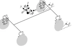
Various vehicle models are used in implementation of the control systems such as antilock braking, active steering, suspension control, and electronic stability program and the complexity of the vehicle model used depends on the type of control system. In this paper, a full vehicle model with look up table tire model is developed for the purpose of predicting the dynamic behavior of the vehicle. The vehicle model presented in this paper is extensively used by researchers as a tool to investigate and enhance vehicle handling. The vehicle model as in Fig. 1 is made up of six degrees of freedom at the vehicle center of gravity and two degrees of freedom at each unsprung mass. Longitudinal, lateral, vertical, roll, pitch, and yaw are the motions at the vehicle center of gravity. The motions of the unsprung mass are the wheel vertical travel and wheel spin. The similar model was used in [4] and [11].
Figure 1. Full vehicle model.
A. Vehicle Modeling Assumptions
In order to simplify the complexity of the actual vehicle, a few assumptions were made to develop the vehicle dynamics model. The steering wheel angles for the front left and right wheels were assumed to be the same. The wheel maintains contact with the road throughout the maneuvers and both wheel and suspension stays normal to the ground. 2011 First International Conference on Informatics and Computational Intelligence
The longitudinal and lateral tire behaviors are represented by the nonlinear table whereby the longitudinal force is a function of slip ratio and normal load and the lateral force is a function of tire slip angle and normal load. Vertical tire behavior is represented by equivalent spring stiffness. Small angles are considered for the vehicle roll, pitch, and yaw angles to avoid the need for coordinate transformation. Suspension spring and damper have linear properties
cos cos
B. Vehicle Modeling
The Fig. 2 shows the handling model which includes the motion along longitudinal axis, lateral axis, rotation about the vertical axis. Fxij and Fyij are the longitudinal and lateral
tire forces respectively. The subscript i denotes front (f) or rear (r) whereas the subscript j represents left (l ) or right (r).
Figure 2. Schematic diagram of vehicle handling model.
As illustrated in Fig. 3(a), the suspension unit for front left corner of the sprung mass consists of a passive spring and damper. Zsij, Zuij, and Zrij are vertical displacement of the
sprung mass corner, vertical displacement of the unsprung mass, and road vertical profile input respectively. Ksij, Csij,
and Ktij are suspension spring stiffness, damping coefficient,
and tire stiffness respectively. The forces acting on front left wheel which is assumed to be the driving wheel are depicted in Fig. 3(b).The driving torque, braking torque and wheel longitudinal velocity are indicated Tdij, Tbij, and Vxij
respectively.
(a) (b)
Figure 3. Schematic diagram of front left quarter car model.
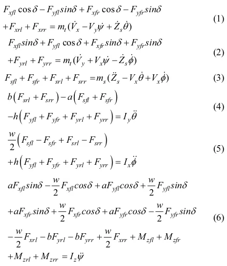
By applying Newton’s Second Law of Motion, the dynamics for the longitudinal, lateral and vertical, pitch, roll and yaw motions are given in equation (1) to (6) respectively. į is the road steering wheel angle, Vx is
longitudinal velocity, Vy is the lateral velocity, a and b are
the sprung mass C.G to front and rear axle distances respectively,h is the height of the sprung mass C.G, w is the track width and mt is the total mass of the vehicle. The roll,
pitch, and yaw angles are denoted by , ș, and ȥ respectively and the moments of inertia for roll, pitch and yaw motions are represented by Ix,Iy, and Iz accordingly.
xrl yrl yrr xrr zfl zfr
zrl zrr z
The resultant force at each unprung mass is determined from the summation of the spring, damper and tire forces acting on the unsprung mass. The dynamics of the unsprung mass vertical motion for front left, front right, rear left, and rear right unsprung mass are given in equation (7) to (10) accordingly.
As shown in Fig. 3(b), the resultant torque on the wheel can be obtained by summing the driving torque, braking torque and moment due to the longitudinal force. The dynamics of the wheel spin for each wheel are as in equation (11) to (14). The effective rolling radius, wheel rotation moment of inertia, and the wheel angular velocity are indicated by R,Iw, and Ȧijrespectively.
the tire lateral force. The nonlinear tire model in Fig. 4 gives a more realistic behavior of the vehicle since it is modeled based on the tire test data.
Figure 4. Tire lateral force depending on tire normal load and slip angle.
C. Vehicle Subsystems Interactions
The vehicle model subsystems interactions in Matlab/SIMULINK are demonstrated in Fig. 5. The suspension model consists of the sprung mass vertical, pitch, and roll motions and each unsprung mass vertical motion. The tire normal load subsystem computes the vertical reaction force at each tire. The tire model subsystem determines the longitudinal tire force which is a function of longitudinal slip ratio and tire normal load and lateral tire force which depends on the tire slip angle and normal load. The handling model subsystem is made of the vehicle longitudinal, lateral, and yaw motions and each wheel rotational motion. The input to the handling model is the steering angle, driving torque or braking torque, and the longitudinal and lateral tire forces.
Figure 5. Interaction between vehicle subsystems.
D. Validation of Vehicle Model
The vehicle model is validated with CarSim software double lane change maneuver. The reason choosing CarSim for vehicle model validation purpose is because the performance of this software in predicting the dynamic behavior of the vehicle is very close to the responses obtained from real world testing. CarSim is proven to be accurately representing the dynamic behavior of the vehicle and it is extensively validated with experimental testing. For double lane change maneuver, the simulation was done in CarSim at a constant velocity of 80 km/h using a D-class SUV vehicle parameters as shown in TABLE I. The input the CarSim for this test is the vehicle desired trajectory in which a driver model is used to generate the steering wheel angle input based on vehicle trajectory given. Since the
vehicle model used in this project did not incorporate a driver model, the steering wheel angle which is the input to the vehicle model was obtained from CarSim software.
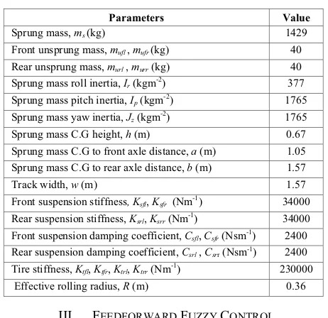
TABLE I. D-CLASS SPORT UTILITY VEHICLE PARAMETERS
Parameters Value
Sprung mass, ms(kg) 1429
Front unsprung mass, mufl,mufr(kg) 40
Rear unsprung mass, murl , murr (kg) 40
Sprung mass roll inertia, Ir (kgm-2) 377
Sprung mass pitch inertia, Ip (kgm-2) 1765
Sprung mass yaw inertia, Jz (kgm-2) 1765
Sprung mass C.G height, h (m) 0.67 Sprung mass C.G to front axle distance, a (m) 1.05
Sprung mass C.G to rear axle distance, b (m) 1.57
Track width, w (m) 1.57
Front suspension stiffness, Ksfl,Ksfr (Nm-1) 34000
Rear suspension stiffness, Ksrl,Ksrr (Nm-1) 34000
Front suspension damping coefficient, Csfl,Csfr (Nsm-1) 2400
Rear suspension damping coefficient, Csrl , Csrr (Nsm-1) 2400
Tire stiffness, Ktfl,Ktfr,Ktrl,Ktrr (Nm-1) 230000
Effective rolling radius, R (m) 0.36
III. FEEDFORWARD FUZZY CONTROL
The Fig. 6 illustrates the roll control strategy based on the road steering wheel angle and vehicle longitudinal velocity using feedforward fuzzy logic control. Fuzzy logic control provides the required moment to counter the roll motion. Decoupling transformation converts the counter roll moment to the actuator forces.
Figure 6. Fuzzy roll control strategy.
A. Relation between Roll Motion and Road Steering Wheel Angle and Vehicle Longitudinal Velocity
The untripped rollover is as a result of the lateral acceleration acting on the vehicle center of gravity due to severe steering input. The lateral acceleration produces the moment which causes the roll motion. The roll moment, M
is related to lateral acceleration, ay by equation (15).
MI m a hs y
(15)
The lateral acceleration is defined as the square of the vehicle longitudinal velocity divided by the radius of the turn, r as shown in equation (16). The radius of the turn depends on the road steering wheel angle and is given by equation (17).
2
x y
V a
a b r G
(17) By rearranging equation (17) and substituting r into equation (16), equation (18) is obtained. Equation (19) is obtained by substituting equation (18) to equation (15). Now, it is obvious that roll moment is directionally proportional to the road steering wheel angle and square of vehicle longitudinal velocity. This is the reason choosing the road steering wheel angle and longitudinal velocity as the inputs to the fuzzy logic control. Also, a simulation study was done by varying the road steering wheel angle and vehicle longitudinal velocity individually. The result of the simulation has proven that the roll angle of the vehicle increases as the road steering wheel angle, vehicle longitudinal velocity or both increases.
2
Active suspension as presented in Fig. 8 is used to reduce the vehicle roll motion by providing counter roll moment. During cornering, lateral force acts at the body center of gravity. Roll moment is created by the lateral force. The controller determines the actuator forces required to create a moment which is equal in magnitude but opposite in direction of the roll moment. There are four actuator inputs Fafl,Fafr,Farl, and Farr which are the hydraulic or pneumatic
actuator forces located at the corners of the vehicle body.
Figure 7. Active suspension.
The counter roll moment due to the actuator forces is given in equation (20).
0.5 ( afl )afr arl arr
MI w F F F F
(20) By matrix manipulation, the actuator force at each corner is
C. Fuzzy Logic Control
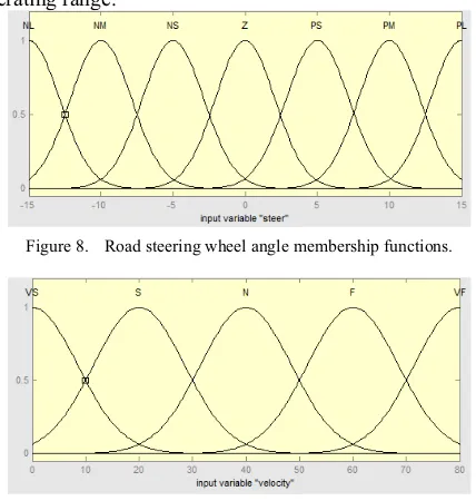
For the fuzzy logic control, road steering wheel angle and the vehicle longitudinal velocity were chosen as the inputs and the counter roll moment was selected as the output. As presented in Fig. 8 to 10, 7 Gaussian membership functions were selected for road steering wheel angle, 5 Gaussian membership functions for the vehicle longitudinal velocity error rate and 7 Gaussian memberships functions for the counter roll moment. The Gaussian membership function was used due to their smooth mapping property. The seven variables for the road steering input and counter roll moment are negative large (NL), negative medium (NM), negative small (NS), zero (Z), positive small (PS), positive medium (PM), and positive large (PL). The five variables for the vehicle longitudinal velocity are very slow (VS), slow (S), normal (N), fast (F), and very fast (VF). The universe of discourse for the inputs was set based on their operating range.
Figure 8. Road steering wheel angle membership functions.
Figure 9. Vehicle longitudinal velocity membership functions.
1
Figure 10. Counter roll moment membership functions.
( )
( )
A A A
A A
z zdz Z
z dz P
P
³
³
(22)where ZA is the crisp output of the fuzzy control, ȝA is the
membership degree of crisp output, z of each rule.
TABLE II. RULETABLE FOR FEEDFORWARD FUZZY CONTROL
Steer / Velocity
Fuzzy Logic Rules
NL NM NS Z PS PM PL
VS Z Z Z Z Z Z Z
S NM NM NM Z PM PM PM
N NL NM NM Z PM PM PL
F NL NL NL Z PL PL PL
VF NL NL NL Z PL PL PL
IV. RESULTS AND DISCUSSION
A. Validation of vehicle model
The vehicle model was validated with CarSim for double lane change maneuver at 80 km/h. As in Fig. 11, the steering angle inputs for the front wheel of vehicle model were taken from CarSim. The roll angle, and roll rate responses are depicted in Fig. 12 and 13 respectively. For roll angle and roll rate responses, the trend of both vehicle model and CarSim are identical with small difference in magnitude compared to CarSim. The main contributing factor to the difference in magnitude between the vehicle model and CarSim responses are the modeling simplification in development of the vehicle model particularly in modeling the suspension system. CarSim is a multibody software whereas vehicle model is developed analytically.
Figure 11. DLC road wheel steering angle.
Figure 12. DLC roll angle response.
Figure 13. DLC roll rate response
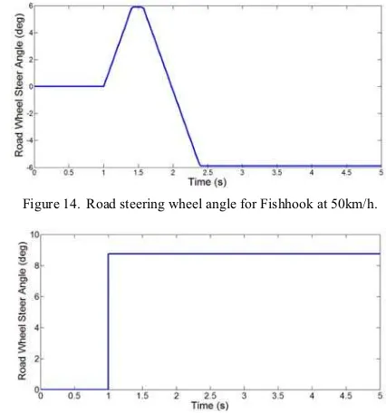
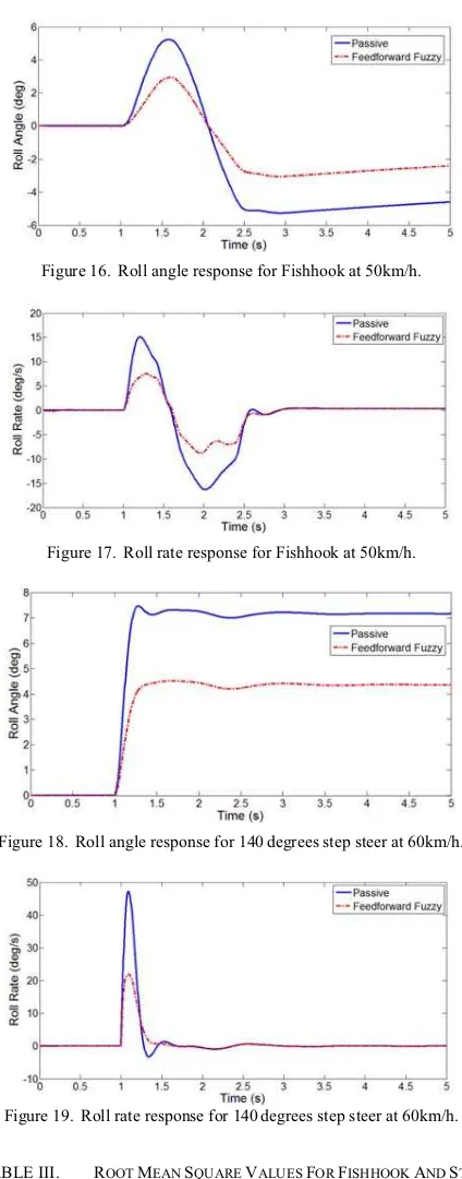
B. Performance Evaluation of the Roll Control Strategy In order to evaluate the performance of the active roll control strategy, the vehicle model was simulated for Fishhook and steep steer maneuvers. The road steering wheel inputs for the Fishhook and step steer maneuvers are illustrated in Fig. 14 and 15 respectively. Fig. 16 and 17 show the roll angle and roll rate variations during Fishhook maneuver at 50 km/h. There are noticeable advantages provided the fuzzy feedforward control in lowering the roll angle and roll rate values with respect to the passive vehicle. Fig. 18 and 19 demonstrates the effectiveness of the feedforward control strategy in reducing the roll angle and roll rate for the 140 degrees step steer maneuver at 60km/h. The performance of the feedforward fuzzy control in terms of the root mean square value is tabulated in TABLE II. For Fishhook maneuver, the improvement of the roll angle and roll rate for the fuzzy feedforward control compared to passive vehicle are 44.90% and 45.41%. The enhancement provided by feedforward fuzzy control during the step steer maneuver is 39.50% for roll angle and 47.73% for roll rate.
Figure 14. Road steering wheel angle for Fishhook at 50km/h.
V. CONCLUSION
From the simulation study, the feedforward fuzzy control based on the road steering wheel angle and vehicle longitudinal vehicle velocity has proven its capability to reduce the roll motion. For both Fishhook at 50km/h and 140 degrees step steer maneuvers, the roll angle and roll rate of the SUV with feedforward fuzzy control were greatly reduced compared to the passive SUV. The reduction in the roll angle signifies that there improvement in preventing rollover under severe driving conditions.
Figure 16. Roll angle response for Fishhook at 50km/h.
ACKNOWLEDGMENT
The authors wish to thank the Ministry of Higher Education (MOHE) and the Universiti Teknologi Malaysia (UTM) for providing the research grant and facilities. This research is supported using a research grant, Vote No. 00H11.
REFERENCES
[1] S. Rakheja, and A. Pichè, “Development of Directional Stability Criteria for an Early Warning Safety Device,” SAE Paper No. 902265, 1990.
Figure 17. Roll rate response for Fishhook at 50km/h.
[2] E. Dahlberg, “A method determining the dynamic rollover threshold of commercial vehicles,” SAE Paper No. 2000-01-3492, 2000. [3] B. Chen, and H. Peng, “Rollover warning for articulated vehicles
based on a time-to-rollover metric,” Proceedings of ASME International Mechanical Engineering Congress and Exposition, Nashville, TN, 1999.
[4] K. Hudha, Z.A. Kadir, M. R. Said, and H. Jamaluddin, “Modeling, Validation, and Roll Moment Rejection Control of Pneumatically Actuated Active Roll Control for Improving Vehicle Lateral Dynamics Performance,” Int. J. Engineering System Modelling and Simulation, Vol 1, No. 2, 2008, pp. 122-136.
[5] A. Sorniotti, and N. D’Alfio, “Vehicle Dynamics Simulation to Develop an Active Roll Control System,” SAE paper No. 2007-01-0828, 2007.
Figure 18. Roll angle response for 140 degrees step steer at 60km/h.
[6] Sampson, D. J. M. and D. Cebon, “Active roll control of single unit heavy road vehicles,” Vehicle System Dynamics, 40(4), 2003, pp. 229–270.
[7] T. J. Wielenga, “A Method for Reducing On-Road Rollovers: Anti-Rollover Braking,” SAE paper No. 1999-01-0123, 1999.
[8] S. Solmaz, M. Corless, and R. Shorten, “A Methodology for the Design of Robust Rollover Prevention Controllers for Automotive Vehicles: Part 1-Differential Braking,” Proceedings of the Conference on Decision and Control, San Diego, 2006.
[9] T. Shim, D. Toomey, C. Ghike, and H. M. Sardar, “Vehicle Rollover Recovery using Active Steering/Wheel Torque Control,” Int. J. Vehicle Design, Vol. 46, No. 1, 2008, pp.51-71.
Figure 19. Roll rate response for 140 degrees step steer at 60km/h. [10] J. Ackermann, D. Odenthal, and T. Bunte, “Advantages of Active
Steering for Vehicle Dynamics Control,” 32nd International Symposium on Automotive Technology and Automation, Vienna, 1999, pp. 263-270.
TABLE III. ROOTMEAN SQUARE VALUES FOR FISHHOOK ANDSTEP
STEERMANUEVERS
Performance Criteria
Root Mean Square Value
Fishhook Step Steer
Passive Fuzzy Passive Fuzzy
Roll angle (deg) 3.987 2.197 6.314 3.820
Roll rate (deg/s) 6.201 3.385 7.324 3.828