Ideal simulation of Al0.3Ga0.7As/InP/Ge multijunction solar cells
Tony Sumaryada, Robi Sobirin, and Heriyanto SyafutraCitation: AIP Conf. Proc. 1554, 162 (2013); doi: 10.1063/1.4820310
View online: http://dx.doi.org/10.1063/1.4820310
View Table of Contents: http://proceedings.aip.org/dbt/dbt.jsp?KEY=APCPCS&Volume=1554&Issue=1
Published by the AIP Publishing LLC.
Additional information on AIP Conf. Proc.
Journal Homepage: http://proceedings.aip.org/
Journal Information: http://proceedings.aip.org/about/about_the_proceedings
Top downloads: http://proceedings.aip.org/dbt/most_downloaded.jsp?KEY=APCPCS
Ideal Simulation of Al
0.3
Ga
0.7
As/InP/Ge Multijunction Solar
Cells
Tony Sumaryada
*, Robi Sobirin and Heriyanto Syafutra
Theoretical Physics Division, Departement of Physics Bogor Agricultural University, Jalan Meranti Kampus IPB Dramaga Bogor, Indonesia 16680
*
Abstract. Increasing the efficiency of solar cell is one of the most challenging tasks for material scientists nowadays. Computer simulation on the other hand, could be used to maximize this effort. In this paper we present our investigations on Al0.3Ga0.7As/InP/Ge multijunction solar cells. These multijunction solar cells were designed and
simulated using PC1D program in two different models. Model 1 focuses on maximizing the efficiency of each subcell, while in model 2 we forced identical current flowing in each subcell. Simulations for both models were performed under ideal conditions of blackbody spectrum at T=6000 K (at the top of atmosphere) and solar intensity of 0.1367 W/cm2.. Our results show that model 1 produces efficiency up to 38.86% compared to 20.26% that produced by model 2.
Keywords: Multijunction solar cell, Solar cell efficiency, III-V Semiconductors, Computer modeling and simulation
PACS: 88.40.jp , 88.40.hj, 81.05.Ea,07.05.Tp
INTRODUCTION
Solar cell is an important device in generating electricity from the sunlight. Most of the commercial solar panels in the market were made from silicon based materials which have efficiency around 7.0 to 15.0%. Other materials which based on III-V group, like GaAs, GaInP, InP, AlGaAs, etc have shown capability in producing electricity with higher efficiencies. The highest recorded efficiency until now is 41.6% that obtained from GaInP/GaInAs/Ge multijunction solar cell [1].
In a multijunction solar cell, several subcells of different materials are stacked together to absorb more power and to minimize radiation lost. Fabricating a multijunction solar cell could be a challenge and a very expensive efforts to do. Simulating the physical process inside the solar cell can be one option to save some works and money. Through the simulation, we can calculate and predict the right parameters needed like thickness, the amount of doping, solar energy absorbed in each subcell, and many others. This prediction can further help the design for the experimental and fabrication processes.
Simulation on multijunction solar cell has been done by many groups [2-4]. Stacking subcells from the highest to lowest bandgap energy, matching the lattice constant of each subcell, stacking more subcells, and
making use of concentrators, are some of the efforts that have been done to boost the efficiency.
In this paper, we simulated Al0.3Ga0.7As/InP/Ge
multijunction solar cell in two different models. Model 1 was designed to maximize the efficiency of each subcell, while model 2 to produce identical current in each subcell. The goal of this research is to study and compare the differences between those models and to decide which model offers a more realistic design.
For the simplicity of simulation, we performed the simulations under ideal conditions by using blackbody spectrum and neglecting the solar radiation lost by the atmospheric gas absorption.
SIMULATION METHODS
In this simulation, subcells were stacked together with the highest bandgap energy put on the top. This design is pretty much like a multistage mesh and is aimed to harness solar energy as much as possible and to minimize the solar radiation lost. Bandgap energy for Al0.3Ga0.7As, InP, and Ge in this research were set
to 1.81, 1.35, and 0.67 eV respectively.
Simulation of solar cell were performed using a freely available PC1D program developed by Basore et al. [7]. This program is able to solve fully coupled nonlinear equations for the quasi-one-dimensional transport of electrons and holes in crystalline semiconductor devices. Since PC1D can only simulate a single cell, we must simulate each subcell individually. Some calculations, like coefficient of absorption, and the amount of solar energy transmitted to each subcell must be done using regular numerical methods and serve as input parameters for the PC1D program.
Blackbody radiation from the surface of the sun of 6000K is used here to calculate the Initial intensity I0
that arrive at the top of the atmosphere. The distance from the sun to the earth (upper atmosphere) is taken to be R = 1.50x10¹¹ m, and the radius of the sun is rsun=6.95x10⁸ m. In the simulation, we defined I0 as the
intensity that hit the first subcell, and is calculated using Eqs. (1) and (2).
2 5 2 1 / exp 1 . sun B hc I hc k T
S
O
O
§ · ¨ ¸ ¨ ¸ ¨ § · ¸ ¨ ¨ ¸ ¸ ¨ © ¹ ¸ © ¹ (1) 2 0 sun earth sunr
I
I
I
R
§
·
¨
©
¸
¹
(2)To obtain the transmitted intensity in each subcell In, one must first calculate the absorption coefficient of
the previous subcell using Eq. (3) [8], then calculate the transmitted intensity using Eq. (4).
( )
5.5 (
E
E
g) 1.5 (
E
(
E
g0.1)
D O
(3)1 ( ) 1
( )
n dnn n
I
O
I
e
D O(4)
It should be noted here that In-1 is the previous
intensity, and dn-1 is the thickness of the previous
subcell.
The total efficiency of solar cell is calculated using Eq. (5).
1 2 3
0
100%
totalP
P
P
x
P
K
(5)With P0 is, I0 multiplied by the area of each subcell
(we use 1 cm2), and P1, P2 and P3 are the output power
in each subcell obtained from PC1D simulation.Fill factor for each subcell is calculated by
100%
.
oc sc
P
FF
x
V I
(6)where P is the output power generated by PC1D simulation.
In both models we have used 1.0 resistance for
the emiter and base contacts.
RESULTS AND DISCUSSIONS
The initial intensity I0 for wavelength that spans
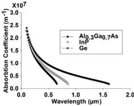
from 0 to 2000 nm was found to be 0.1367 W/cm2. The transmitted intensity to the next layer is depend on the coefficient of absorbtion and bandgap energy of the previous layer, as shown in Eqs. (3) and (4). The profile of absorbtion coefficient of each subcell is shown in Fig. 1.
FIGURE 1. The absorbtion coefficient of each subcell calculated using Eq. (3).
The multistage absorbtion of solar radiation by the solar cell is demonstrated in Fig. 1. Al0.3Ga0.7As
subcell only responds to a high energy radiation below 690 nm. InP subcell responds to medium energy radiation below 920 nm, while Ge responds to low energy radiation below 1860 nm. Theoretically, to minimize the radiation lost, one can put as many layers as possible. Once we identify the transmitted intensity to the next layer, then we can run PC1D simulation for the next layer. Since, we deal with a triple junction solar cell, we need to perform three calculations of intensity, I0, I1, and I2 in each model.
simulation to find a particular thickness that produce the highest current. The same method has also been deployed to find the optimum doping in each subcell.
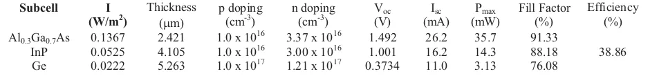
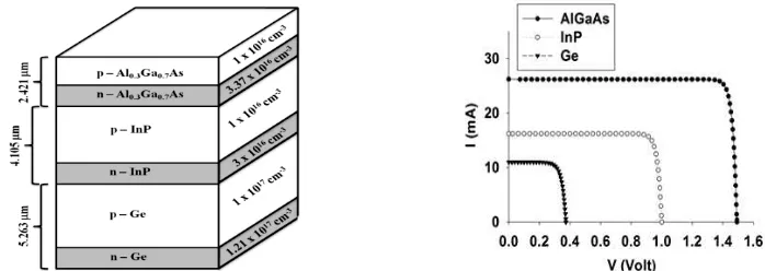
Input parameters and results for model 1 are shown in Table.1. The schematic design and performance of this model (I-V curve) can be seen in Fig. 2. Since the current produced by a subcell is proportional to the amount of solar radiation, the first subcell that receives abundance of photons should be made thinner. The opposite way is also true for the last subcell that receives smaller amount of solar radiation. The simulation results from both models agree with that statement. The first subcell Al0.3Ga0.7As becomes the
thinnest layer, while the last subcell (Ge) which only receives around 16% of the initial intensity I0 ,
becomes the thickest layer in solar cell in order to absorb more photons.
Results from other parameters also in agreement with the explanation above. The amount of Voc, ISC,
power, and fill factor for each subcell show the tendency to decrease. Off course with the exception in model 2, where the currents were intentionally set to be constant. Input parameters and results for model 2 are shown in Table 2, while the schematic design and performance of this model (I-V curve) can be seen in Fig. 3.
Al0.3Ga0.7As in model 1, has produced 35.7 mW
power that equal to 26.11% subcell’s efficiency (from (35.7 mW/136.7 mW) x 100%). In model 2, since the current is limited, the subcell’s efficiency is reduced to 10.68%. The same thing occurred for InP and Ge.
InP subcell’s efficiency decrease from 27.23 % in model 1 to 19.50% in model 2. Ge subcell’s efficiency
decreases from 14.09% in model 1 to 13.02% in model 2.
The thickness of p and n layer in each subcell is calculated automatically in PC1D program. In model 1, the thickness of p and n layer of Al0.3Ga0.7As is
1.6832 and 0.7378 m respectively, while for InP is 3.4209 and 0.6841 m, and for Ge is 5.108 and 0.155
m. In model 2, the thickness of Al0.3Ga0.7As is 1.817
and 1.163 m respectively, while for InP is 7.705 and
1.821 m, and for Ge is 28.227 and 1.163 m.
The current and voltage characteristics of model 1 and model 2 are very different. In model 1, since we only focus on maximizing the output of individual subcell, we obtain three separate I-V curve. In model 2, all subcells produce identical current.
Eventhough we could boost the efficiency in model 1 up to 38.86%, but in terms of design, it is unrealistic to combine three subcells with three different values of current in a series connection. The same unrealistic design, if we want to combine three different values of voltage in a parallel connection. Model 1 is clearly unrealistic here, and only serves as a paedagogical model to help one to get the insight of energy conversion process in a solar cell.
Model 2 is a more realistic one, since the identical current corresponds to a series connection of three different subcells in a solar cell. Our simulation so far can only produce 20.26% efficiency, but there are still rooms for improvement. Some of the improvements that we can do in the future are, optimization of the input parameters, like doping and thickness, and the use of concentrators that is able to multiply the light intensity by several hundred times [1-3].
[image:4.612.65.535.481.536.2]
TABLE 1. Input parameters and ouputs of model 1.
Subcell I (W/m2)
Thickness (Pm)
p doping (cm-3)
n doping (cm-3)
Voc (V) Isc (mA) Pmax (mW) Fill Factor (%) Efficiency (%)
Al0.3Ga0.7As 0.1367 2.421 1.0 x 10
16
3.37 x 10¹⁶ 1.492 26.2 35.7 91.33
38.86
InP 0.0525 4.105 1.0 x 10¹⁶ 3.00 x 10¹⁶ 1.001 16.2 14.3 88.18
[image:4.612.64.534.569.622.2]Ge 0.0222 5.263 1.0 x 10¹⁷ 1.21 x 10¹⁷ 0.3734 11.0 3.13 76.08
TABLE 2. Input parameters and outputs of model 2.
Subcell I (W/m2)
Thickness (Pm)
p doping (cm-3)
n doping (cm-3)
Voc (V) Isc (mA) Pmax (mW) Fill Factor (%) Efficiency (%)
Al0.3Ga0.7As 0.1367 2.980 1.0 x 10
19
1.0 x 10²⁰ 1.3550 11.9 14.60 90.20
20.26
InP 0.0523 9.551 1.0 x 10¹⁸ 1.0 x 10²⁰ 0.9761 11.9 10.20 87.60
FIGURE 2. Design and Performance of Model 1 that produced 38.86 % total efficiency.
FIGURE 3. Design and Performance of Moel 2 that produced 20.26 % total efficiency.
SUMMARY AND CONCLUSIONS
We have performed an ideal simulation of Al0.3Ga0.7As multijunction solar cell in two different
models. Model 1 can produce efficiency up to 38.86%, but this model is unrealistic due to a different value of currents and voltages in each subcell. Model 2 on the other hand, eventhough only produces 20.26% efficiency, offers a more realistic design due to identical currents flowing in each subcell that corresponds to a series connection of Al0.3Ga0.7As,
InP, and Ge in a solar cell system.
A more realistic simulation that employs standard radiation spectrum (AM0, AM1.5D, AM1.5G), and more precise simulation parameters and also the use of light concentrators, is the work in progress.
ACKNOWLEDGMENTS
We would like to thank A.A. Setiawan and A.W. Roslia for helpful discussion during the research.
REFERENCES
1. R. R. King, A. Boca, W. Hong, X. Q. Liu, D. Bhusari, D. Larrabee, K. M. Edmondson, D. C. Law, C. M. Fetzer, S. Mesropian, and N. H. Karam., "Band-Gap-Engineered Architectures for High-Efficiency
Multijunction Concentrator Solar Cells," in 24th European Photovoltaic Solar Energy Conf., Hamburg, Germany, Sep. 21-25, 2009.
2. E. Reineri, T. Yu. “AlGaAs/InP/Ge High Efficiency Solar Cel”, Master Thesis, San Jose State University, 2010.
3. R. R. King, D. C. Law, K. M. Edmondson, C. M. Fetzer, G. S. Kinsey, H. Yoon, R. A. Sherif, and N. H. Karam, Appl. Phys. Letters 90, 183516(1-3) (2007). 4. L. Siyu and Q. Xiaosheng, Journal of Semiconductors
32(11), 112003 (1-4) (2011).
5. M. Yamaguchi, Solar Energy Materials and Solar Cells
75, 261-269 (2003).
6. F. Dimroth, Phys.Stat.Sol.(c)3, 373-379 (2006). 7. P. A. Basore and D. A. Clugston, “PC1D Version 5: 32
-Bit Solar Cell Modeling on Personal Computers” in 26th IEEE Photovoltiac Specialists Conference, Anaheim, Sep-Oct 1997, pp.207- 210.