Flexural Capacities and Stress Block Parameters for High-Strength
Concrete Column
K
APASITASL
ENTUR DANP
ARAMETERB
LOKT
EGANGAN PADAK
OLOMB
ETONM
UTUT
INGGIAntonius1) 1)
Department of Civil Engineering, Universitas Islam Sultan Agung (UNISSULA), Semarang, e-mail: [email protected]
ABSTRACT
Flexural behaviour of reinforced high-strength concrete columns is studied in this paper. Tests of 12 high-strength reinforced concrete columns under eccentric loading were conducted, with test parameters included the concrete strength, longitudinal reinforcement ratio, load eccentricities and lateral reinforcement characteristics i.e: spacing and volumetric ratio. Concrete strength used were around of 50 and 70 MPa. From this study, the main result shows that curvature ductility increase with increasing volumetric ratio or reduction of tie spacing for lateral reinforcement. Comparison between stress block parameter models developed by many researchers with the test results was evaluated. It is found that the model adopted in the Indonesian National Standard (SNI 03-2847-2002) and ACI need to be modified before they can be utilized in the flexural design of structures made of high-strength concrete.
Key words: high-strength concrete, flexure, stress block parameter, interaction diagram
ABSTRAK
Paper ini menyajikan suatu studi mengenai perilaku lentur pada kolom beton bertulang mutu tinggi. Pengujian dilakukan terhadap 12 buah kolom beton bertulang mutu tinggi yang dibebani secara eksentrik, dengan meninjau bebeRAPa parameter yaitu kuat tekan beton, rasio tulangan longitudinal, eksentrisitas beban dan karakteristik tulangan lateral seperti spasi dan rasio volumetrik. Kuat tekan beton yang digunakan berada di kisaran 50 dan 70 MPa. Dari hasil studi ini, hasil utama menunjukkan bahwa daktilitas kurvatur spesimen akan meningkat dengan peningkatan rasio volumetrik atau reduksi spasi tulangan lateral. Perbandingan antara model-model parameter blok tegangan yang telah dikembangkan oleh para peneliti dengan hasil pengujian juga dievaluasi dalam studi ini. Berdasarkan hasil evaluasi ditemukan bahwa model blok tegangan yang diadopsi di dalam Standar Beton Indonesia (SNI 03-2847-2002) dan ACI perlu dimodifikasi terlebih dahulu sebelum diaplikasikan dalam desain lentur untuk struktur yang terbuat dari beton mutu tinggi.
Kata-kata kunci: beton mutu tinggi,lentur, parameter blok tegangan, diagram interaksi
INTRODUCTION
Until the last decade, high-strength concrete (HSC) ma- terial is more popular because the main mechanical properties, i.e. high performance, capacity, durability and other propertis. One of the advantageous characteristics of high strength con-crete enables the use of reinforced concon-crete columns with smaller cross sectional dimensions for high-rise buildings and longer the bridge span for pre-stress concrete beam. Several design equation of high-strength concrete have published and proposed for the design application of structural members; i.e: Ibrahim & Mac Gregor (1997), CEB-FIP (2008), Mertol et al. (2008).
It is convenient, to define an arbitrary lower limit for the definition of high-strength concrete. Based on summary of many investigations of HSC and current design practices and equations in Indonesian National Standard for reinforced con-crete design (SNI 03-2847-2002) and ACI 2005, in this paper the limit of 50 MPa is used to define the lower limit of high-strength concrete.
HSC material tends to substantial questions concerning not only the bearing capacity, but also its ductility and post-peak behavior. High-strength concrete members usually suffer from lower ductility and exhibit premature spalling of con-crete cover under high compression [Bae & Bayrak, 2003 and Antonius, 2004]. Deformability of reinforced concrete co-lumns under earthquake loadings is the essential and signifi-cant influence the stability of structures. A better understand-ding of high-strength concrete behavior in reinforced concrete
structures such as columns is needed, also verified available models are required.
It is well known that concrete confined by lateral reinforce-ment indicated increased strength and ductility. Many researchers have put a relatively large amount of effort into understanding the confinement mechanism and introducing a suitable model for the behavior of confined concrete in reinforced concrete elements sub-jected concentric and eccentric loadings. Antonius (2011) showed that design variables such as the confining reinforcement charac-teristics are the important factor that influence the strength and duc-tility confined concrete columns under eccentric loadings. Moment-curvature relationships obtained based on confinement model deve-loped for concentric compression produced good correlations with envelopes of experimentally obtained moment-curvature hysteretic relationships.
Consequence in the design of reinforced concrete members with flexure is rectangular compression stress block in the current code provisions need to be evaluated. The design equations of stress block parameters in the SNI and ACI code are limited for concrete strength up to 55 MPa. Therefore, it is need to investigate the accu-racy of the equations for the design of structural members construc-ted of higher strength concrete.
EXPERIMENTAL TEST
Twelve high-strength concrete columns were produced with the design parameters of concrete strength, characteristics of lateral reinforcement, number of longitudinal reinforcement and ratio of end eccentricity to the length of columns cross section.
Materials
Two different mixes were used to set cylindrical strength target of high-strength concrete (50 and 70 MPa). The sand and coarse aggregate used were taken from a local pit. The maximum size of coarse aggregate used is 14 mm. The super-plasticizer (SP) with brand name of Sikament NN was used to improve the workability of the high-strength concrete mix. Fly Ash with fifteen percent by weight of the Portland cement was substituted in the mix design.
The lateral reinforcement used was plain rebar with 5.5 mm diameter, with the yield stress of 315 MPa, and longitudi-nal reinforcement was deformed bars with 10 mm diameter with the yield stress of 340 MPa. Yield stress of reinforcement was determined by tension tests and the stress-strain curves shown in Figure 1.
Figure 1. Stress-strain curves of lateral and longitudinal reinforcement
Specimen Details and Instrumentation
In this research, twelve columns had a square sections 120x120 mm and height 700 mm were produced. Two of these did not have reinforcement in the test region as the control specimens. Figure 2 shows the column cross-section and ins-trumentation. Concrete cover of nominally 10 mm was used in the specimens. Test region was 350 mm length in the middle height of columns. Strain gauges with FLA-5 type were used to monitor strains in reinforcements, and displacement trans-ducers (LVDT) were used to measure axial and lateral defor-mations in tested columns.
All instrumentations were connected to the computer ba-sed on data acquisition system. All columns were tested under monotonically increasing axial compression with constant end eccentricity in Universal Testing Machine (UTM) with 1000 kN capacity. The tests were done under displacement control. The load was given in regular increment, and sets of deforma-tion readings were taken in every load stage. The measured experimental variables were axial force, longitudinal and lateral deflections of specimens, strain of reinforcement. The type and character of the failure was also observed.
Flexural Strength and Ductility Analysis
The flexural strength measured by multiply load of column with the eccentricitiy. The bending capacity can be calculated with reasonable accuracy using the rectangular stress block parameters defined by codes (SNI and ACI). Confined concrete area in this stu-dy is measured from center to center of perimeter steel. Curvature ductility ratio () was determined as the ratio of curvature of confi-ned concrete at 85 percent of the maximum moment on the descen-ding branch to curvature of unconfined concrete correspondescen-ding to the maximum moment.
TEST RESULTS AND DISCUSSION
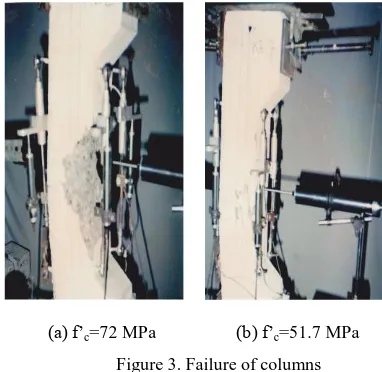
Loads, moments and curvature ductility from tests results are listed in Table 1. The specimen control (CC1 and CC2) failed sud-denly in an explosive manner. Figure 3 shows examples of failure of columns with concrete strength of 51.7 MPa and 72 MPa. The speci-mens failed by crushing in the most compressed fibers near the com-pression face. The figures also describe that for higher strength con-crete, failure of the specimen signed by crushing at the compression zone is more brittle.
(a) f‘c=72 MPa (b) f‘c=51.7 MPa
Figure 3. Failure of columns
In specimens with concrete strength 72 MPa showed smaller the flexural capacity than predicted based on analysis (Mmax/MSNI
<1). Otherwise, in lower strength concrete (f‘c=51.7 MPa) the
flexu-ral capacity tends higher than prediction adopted in the codes, whe-reas the ratio of maximum moment based on experiments to the mo-ment calculation is greater one. The implication of this phenomenon indicate unconservative prediction of the flexural equations used in the SNI and ACI codes for high-strength concrete columns.
Curvature ductility values as shown in Table 1 are influenced by confinement of lateral reinforcement installed. Design parameters of confinement also affect directly the curvature ductility.
0 100 200 300 400 500 600
0 0.02 0.04 0.06 0.08 0.1 0.12 0.14 0.16 0.18
Strain
S
tr
ess (
M
P
a)
Lateral reinf. Longitudinal
Figure 2. Detail of column specimens
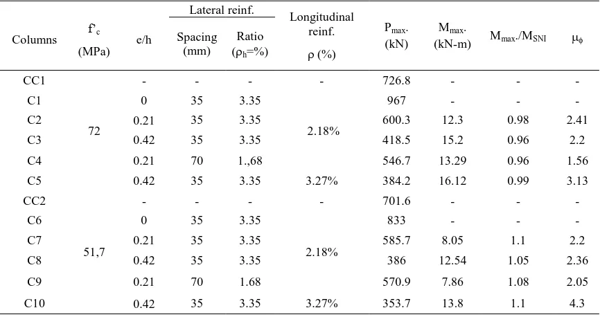
Table 1. Properties of Specimens and Test results
Columns f‘c
(MPa) e/h
Lateral reinf.
Longitudinal reinf.
(%)
Pmax.
(kN)
Mmax.
(kN-m) Mmax./MSNI Spacing
(mm)
Ratio (h=%)
CC1
72
- - - - 726.8 - - -
C1 0 35 3.35
2.18%
967 - - -
C2 0.21 35 3.35 600.3 12.3 0.98 2.41
C3 0.42 35 3.35 418.5 15.2 0.96 2.2
C4 0.21 70 1.,68 546.7 13.29 0.96 1.56
C5 0.42 35 3.35 3.27% 384.2 16.12 0.99 3.13
CC2
51,7
- - - - 701.6 - - -
C6 0 35 3.35
2.18%
833 - - -
C7 0.21 35 3.35 585.7 8.05 1.1 2.2
C8 0.42 35 3.35 386 12.54 1.05 2.36
C9 0.21 70 1.68 570.9 7.86 1.08 2.05
C10 0.42 35 3.35 3.27% 353.7 13.8 1.1 4.3
Columns with greater than 3% volumetric ratio of lateral reinforcement and six laterally supported longitudinal reinfor-cements shows higher ductility value, others with four longitu-dinal reinforcement shows smaller ductility. Detail of the ef-fect of these confinement for specimens under eccentric lo-adings has presented by author (2011).
STRESS BLOCK PARAMETERS
Rectangular stress block equations adopted in Indonesi-an Concrete Code (SNI) to estimate the flexural strength of high-strength concrete specimens and the results shown in Table 1 are unconservative predictions for column capacity. Hence, evaluation of models of stress block parameter is great significance.
Figure 4 draws the stress block parameters that could be obtained from tests, they are k1, k2 and k3. Definition the
recta-ngular stress block defines by the parameters 1 and 1 as
shown in the Figure. The k3 factor takes account of several
factors that contribute to the differences between the in situ compressive strength of concrete and the strength determined from standard cylinders. The k2 factor represents the stress
block depth factor while the k1 factor is the stress block width
factor. The relationship between the parameters used in this paper and conventional terminology is that k1k3 is equal to α
and k2 is equal to β1.
700 mm
Test Region = 350 mm
125 mm 125 mm
Bout
Bout Glass
LVDT T
Plate Plate
A
A
C
120 mm
120 mm
Section A-A
Figure 4. Stress block parameters
Table 2. Rectangular stress block models
Model k1k3 (=1) k2 (=1)
SNI 2002/ACI 0.85 1.09–0.008 f‘c
0.85k20.65
Attard &
Steward (1998) 1.29(f‘c)-0.10.71
1.095 (f‘c)-0.091
0.67
NZS3101-1995 1.07–0.004 f‘c 0.85k1k30.75
1.09–0.008 f‘c
0.85k20.65
Ibrahim & MacGregor (1997)
0.85-f‘c/800
0.725
0.95-f‘c/400
0.70
Bae & Bayrak (2003) 0.85-0.004(f‘c-70) 0.85-0.004(f‘c-30)
Mertol et al. (2008)
0.85 for f‘c≤69 ksi
0.85-0.0029(f‘c-69)≥0.75 for
f‘c>69 ksi
0.85 for f‘c≤28 ksi
0.85-0.007252(f‘c-28)≥0.65 for f‘c>28 ksi
Table 2 shows the rectangular stress block models adop-ted in codes and proposed by researchres. The code provisions by SNI, similar with ACI, 1 is assumed to have a constant
va-lue of 0.85. The parameter 1 is equal to 0.85 for concrete
strengths up to 30 MPa and is reduced gradually at a rate of 0.08 for each 10 MPa of concrete strength in excess of 30 MPa to the limit that 1≥0.65. The ultimate compressive strain εmax
is taken to have a constant value of 0.003 for all concrete strengths. Similar equation of 1 in New Zealand Standard
(NZS3101-1995) but for 1 value is differ.
Attarrd and Steward (1998) proposed a model relate to mean cylinder concrete strength and specified strength for use in the design formulas. Hence the equations of 1 and 1 were
non-linear and tends decrease with the increasing of concrete strength. The model proposed by Ibrahim & Mac Gregor (1997) select a value of 1 from test results of 20 high-strength
column specimens. The parameter 1 was derived to provide a
conservative lower bound for the experimental data on k3.
The model proposed by Bae & Bayrak (2003) based on main consideration that effect of early cover spalling of high-strength concrete column tests. The stress-strain curve recom-mended by Collins et al used to determine parameters of the stress block.
Mertol et al (2008) proposed the model based on collec-ting data and experimental program of 21 plain concrete in the test regions. They proposed for the generalized stress block parameters, and the lower bound relationships for rectangular stress block parameter 1 is 0.75 and for 1 is 0.65.
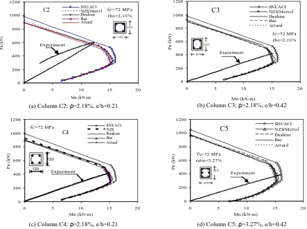
Furthermore, the models explained above were exami-ned with the column test results through the interaction dia-grams of axial load versus moment. Column specimens obtained as validation, they are C2, C3, C4 and C5 for speci-mens with concrete strength of 72 MPa and specispeci-mens of C7, C8, C9 and C10 for columns with concrete strength of 51.7 MPa. It can be seen from Figure 5 that for specimens with concrete strength 72 MPa, the SNI and ACI interaction
dia-grams overestimate for the capacity of axial and flexural capa-cities. All interaction diagrams for specimens with concrete strength of 51.7 MPa shows conservative in the capacities of axial load and moment (Figure 6).
CONCLUSIONS
Studies on the flexural behaviour of reinforced high-strength concrete columns is presented include the analysis, experimental program and examined the equation models to the test results. Lateral reinforcement characteristics and a number of longitudinal reinforcement have important role in determining the flexural capacities and ductility of high-strength concrete columns. The current SNI and ACI recta-ngular stress block parameters for design for high-strength concrete columns with concrete compressive strength of 72 MPa with flexure are overestimate in the prediction capacities. Hence it is need to modified stress block parameters in the current codes. Other alternative models proposed by research-hers, such as models by NZS, Mertol, Ibrahim, Bae or Attard, could be utilized in designing for high-strength concrete columns.
1.h 1.fc‘
h b
Compression zone Rectangular
stress block
max
Concrete strain
k3.fc‘
Concrete stress
C=k1.k3.fc‘.b.h
k2.h 0.51.
h
Figure 5. P-M Diagram of rectangular stress block models with experiments; f‘c=72 MPa
(a) Column C7; ρ=2.18%, e/h=0.21 (b) Column C8; ρ=2.18%, e/h=0.42
(c) Column C9; ρ=2.18%, e/h=0.21 (d) Column C10; ρ=3.27%, e/h=0.42
ACKNOWLEDGMENTS
Funding for this experimental program was provided by Di-rectorate General of Higher Education, Ministry of National Education, Republic of Indonesia through the Competitive Re-search Program. The contributions received for this reRe-search are gratefully acknowledged.
NOTATIONS
α, β1 = stress block parameters
e = loading eccentricity
c = strain of concrete
max =cu = ultimate strain of concrete
85c = strain of confined concrete at 85% of confined
concrete peak stress f = stress of concrete
f‘c = concrete compressive strength of cylinder
150x300 mm at 28 days k1, k2 ,k3 = stress block parameters
Mmax = maximum moment of column under flexure
Ø = curvature
μØ = curvature ductility
h = ratio of lateral reinforcement
= ratio of longitudinal reinforcement
REFERENCES
ACI Committee 318 (2005), ―Building code requirements for structural concrete (ACI 318-05) and commentary (318R-05)‖, American Concrete Institute, Farmington Hills, MI, pp.430.
Antonius (2011), ―Confinement effects on high-strength concrete columns subjected eccentric loading‖,
Proceeding of The 4th ASEAN Civil Engineering
Conference, Yogyakarta, Indonesia, 22-23 Nov., pp.21-26.
Antonius (2004), ―The influence of lateral reinforcement to the cover spalling mechanisms of high strength concrete column structures‖, Proc. of National Conference of
Earthquake Eng. II, Gajah Mada Univ., Indonesia,
pp.168-176, (in Indonesian).
Attard, M.M. and M.G. Steward (1998), ―A two parameter stress block for high-strength concrete‖, ACI Structural
Journal, V.95 (3), pp.305-317.
Bae, S. and O. Bayrak (2003), ―Stress block parameters fo high-strength concrete members‖, ACI Structural Journal, V.100 (5), pp. 626-636.
CEB-FIP (2008), Constitutive Modelling of High Strength/High Performance Concrete; State of the Art
Report, January.
Foster, S.J. and M.M. Attard (1997), ―Experimental tests on eccentrically loaded high-strength concrete columns, ACI
Structural Journal, V.94 (3), pp.295-303.
Indonesian National Standard (2002), Computational Method
of Reinforced Concrete Structures for Building,
SNI-03-2847-2002 (in Indonesian).
Ibrahim, H.H.H. and J.G. MacGregor (1997), ―Modification of the ACI rectangular stress block for high-strength concrete‖. ACI Structural Journal, V.94 (1), pp.40-48. Mertol, H.C., S. Rizkalla, P. Zia, and A. Mirmiran (2008),
―Characteristics of compressive stress distribution in high-strength concrete‖, ACI Structural Journal, V.105 (5), pp.626-633.
Steward, M.G. and M.M. Attard (1999), ―Reliability and model accuracy for high-strength concrete column design‖, Journal of. Struct. Eng. ASCE, V.125 (3), pp. 290-300.
Teng-Hooi, Tan and Ngoo-Ba Nguyen (2005), ―Flexural behavior of confined high-strength concrete columns‖,