Development of Passive Quarter Car Suspension Prototype
Che Amran Aliza
1,a, Fen Ying Chin
2, Md Ghazaly Mariam
1and Shin Horng
Chong
11
Center for Robotic and Industrial Automation (CeRIA), Faculty of Electrical Engineering, Universiti Teknikal Malaysia Melaka, Hang Tuah Jaya, 76100 Durian Tunggal, Melaka, Malaysia
2
Faculty of Electrical Engineering,
Universiti Teknikal Malaysia Melaka, Hang Tuah Jaya, 76100 Durian Tunggal, Melaka, Malaysia
a
Keywords: Quarter car model, Passive suspension system, Car body displacement, Tire
displacement
Abstract. In this paper, a construction of a prototype to represent passive vehicle suspension system
for quarter car model is considered. The prototype is represented by two degree-of freedom quarter-car model which are conventionally used by researchers. This laboratory equipment is developed in order to familiarize students with 2 DoF passive suspension system model. It consists of two masses, two springs and a damper. This equipment is easily dismantled and could be assembled with different spring and damper constants which contribute to different characteristics of the suspension system. A number of experiments have been carried out using the experiment setup in order to identify the suspension system characteristics i.e. experiments with different vehicle body mass, different period for one pulse and different pulse width of input pressure of the road excitation have been conducted. The experiment results are evaluated based on the vehicle body displacement and tire displacement of the prototype. Experiment results show that the pulse width of the input pressure or road profile is directly affected the characteristic of this passive suspension system. Lastly, simulations were done in order to compare the simulation and experiment results. Next step is to implement active control to this system via active actuators.
Introduction
The car suspension systems can be divided into three types which are passive, semi-active, and active suspension system. The passive suspension system is an open-loop control system that does not contain any external energy sources and only consists of passive elements which are spring and shock absorber. Passive suspension system has the ability to store energy via a spring and dissipate it via a shock absorber. However, passive suspension system does not have the function of supplying energy to the system for corrective actions. The performance of the passive suspension system can be improved by adding active components to the system. Semi-active suspension system is modified from passive suspension system by changing the shock absorber to a variable shock absorber [4]. The damping coefficient of the shock absorber can be adjusted in order to follow the road conditions. Active suspension system is a closed-loop control system that consists of external energy source. It is modified by adding force active actuator to the system. The performance of the active suspension system can be adjusted due to its closed-loop control system characteristic. Besides that, it has the ability to store, dissipate and to introduce energy to the system. The active controller will calculate amount of energy need to be added or dissipated from the system in order to keep the tire in touch with the road and thus improve the handling quality and ride comfort [2]. In control education, many laboratory scaled prototypes have been developed in order to demonstrate the students real physical responses using simplified model of a complex system. The car suspension system is chosen because there are only a few laboratory setup or plant designed for such system, the latest experiment setup that is within the author’s knowledge is ‘The Active Suspension System’ developed by Quanser. The objective of this paper is to develop a low-cost prototype to be used as a laboratory experimental plant for control engineering degree students. In
A
cc
ep
te
d
fo
r
pu
bl
ic
Malaysia, real-time experiments with customized lab-scaled equipments/systems usually come with high costs. The main factor that lead to this high cost is Malaysia needs to import/purchase these equipments from other countries. Due to this reason, number of equipments purchased are usually small in numbers. This will create a high student to equipment ratio during laboratory sessions. To avoid this problem, the real-time experiment setup could be fabricated and customized using local expertise and materials. Not only the costs could be reduced, affordable maintenance could be carried out. Despite of the ability to cut down costs, producing a product with local expertise could motivate the local manufacturers to improve, gain experience and be able to compete with other well-known manufacturers. As a whole, the research industry in Malaysia could improve positively and be able to produce good quality research products for local and international markets.
In this paper, a real-time experiment setup to represent vehicle suspension system is proposed. As the first step, the developed prototype is tested for its characteristics by exciting the prototype with pneumatic actuation representing the road profile. As a result, limitations of the prototype can be identified before proposing a control algorithm using active actuators that will be built to the prototype. Furthermore, by studying its open loop responses gives the opportunity to change and adjust the prototype’s design parameters at early stage of the laboratory equipment development process. Next step for this project is to propose a control strategy using active actuators that will be added to this prototype.
Design and Physical Structure
A typical quarter car suspension model consists of masses, springs and a passive damper. Fig.1(a) shows the two-degree-of-freedom modeling of the quarter car passive suspension system and (b) shows the free body diagram of this passive suspension system, where
Ms mass of car body
Mus mass of wheel and tire
ks spring constant of suspension
bs damping coefficient of gas damper
kt spring constant of tire
Xs displacement of Ms
Xus displacement of Mus
r road disturbance input
Fs spring force
Fd suspension damper force
Ft tire force
This quarter car model consists of one sprung mass (car body) and one unsprung mass (wheel and tire). There is a spring and a damper connected in parallel between the sprung mass and unsprung mass which represents the suspension system. Furthermore, there is a spring connected below unsprung mass and this acts as the stiffness of the tire.
(a) Schematic diagram (b) Free body diagram
Fig. 1 Diagram of a quarter car passive suspension model
Ms
ks bs
Mus
Xs
Xus
kt
r
Xs
Xus
Ms
Mus
Fs Fd
Ft
A
cc
ep
te
d
fo
r
pu
bl
ic
The developed quarter car passive suspension system prototype consists of fourteen bearings, three Infrared sensors (IR-sensor), one gas spring, one double acting cylinder, two flow control valve, one pressure regulator, one 5/2 way valve and two springs with different spring coefficient. Apart from these items, the setup also consists of a laptop which connects to a set of Micro-Box 2000/2000C. Fig.2(a) shows the schematic view of experimental setup while (b) shows the photograph of the prototype. By referring to Fig.2(a), the green line represents the compressed air supply from the small air compressor to the double acting cylinder. The air supplied is passing through the pressure regulator and 5/2 way valve before reaching the double acting cylinder. The red line is the analog signal that sends from IR-sensors to the Micro-Box. The analog signal received by the Micro-Box is stored and display using software Matlab 2009a. The cyan line represents the output signal sent from Micro-Box which is used to control the operation of the double acting cylinder. Lastly, yellow line is the Ethernet line that connects laptop and the Micro-Box for communication purpose.
As shown in Fig. 2a, there are three plates involved in this setup. Plate 1 is the road surface and the double acting cylinder produces road disturbance input (upward vertical force) to the suspension
system. Plate 2 represents Mus and plate 3 represents Ms. Additional masses could be applied by
adding weighs on these plates. IR sensors are placed to measure displacements of these three plates with respect to their initial position. This structure can easily be dismantled and assembled which gives the opportunity and advantage of varying the system parameters. Also for this protoype spring
constant kt is chosen to be stiffer than ks.
(a) Schematic diagram (b) Photograph of the prototype
Fig. 2 The developed prototype
Derivation of Mathematical Model
A schematic diagram and free body diagram of quarter car are developed in order to obtain the equation of the motion which can describe the dynamic behavior of quarter car. The mathematical model is derived by applying Newton’s law to each mass and then identifying the forces acting on each mass. Since this is 2 DoF system, there will be two equations of motion i.e. one for the vehicle body mass and the other one is for the wheel mass. By referring to the free body diagram in Fig. 1(b), it can be noticed that there are three different forces acting on vehicle body and wheel. The three forces are suspension spring force, suspension damper force and tire force respectively.
Laptop Micro-Box
Set Air Compressor Sensor
Pressure Regulator
Sensor
5/2 way valve Double Acting
Cylinder Load
A
cc
ep
te
d
fo
r
pu
bl
ic
For vehicle body mass Ms applying Newton’s second law of motion by assuming upward
direction as positive. There are two forces which are suspension spring force Fs and suspension
damper force Fd acting upward on the vehicle body. Therefore, the force exerted on the vehicle
body mass is shown in Eq.1.
��+ �� =����̈
��(���− ��) + ��(�̇��− �̇�) =����̈ ...(Eq.1)
For wheel mass Mus , there are three forces which are suspension spring force, suspension
damper force and tire force acting on the wheel and tire. Thus, the force exerted on Mus is shown in
Eq.2.
��− (��+��) =����̈��
��(� − ���)− ��(��� − ��)− ��(�̇��− �̇�) =����̈�� ...(Eq.2)
Equation 1 and 2 represent the equations of motion for the quarter car passive suspension system These two equations are represented in Simulink Model of MATLAB in order to simulate the dynamics behavior of quarter car model.
Results and Discussions
In order to observe the response of this prototype given disturbance input, a number of experiments have been carried out as shown by Table 1. The first parameter varied is car body mass
Ms. Second and third parameter variation are done on the disturbance input signal.
Fig. 3 Road disturbance profile, r
In MATLAB, the signal injected to the pneumatic cylinder is continuous square-wave signals. Due to time delay of the pneumatic system, its output becomes a continuous saw-tooth signal as captured by the IR sensor. For conducting the experiments, these square-wave pneumatic signals are manipulated i.e. its pulse width [%] and the period of one cycle [sec]. Fig.3 shows the input signal sent (blue) and the Plate 1 displacement measured by IR sensor (filtered) (pink).
As mentioned earlier, experiments with different Ms have been carried out. There are three mass
tested for Ms i.e. 4.29, 4.59 and 4.79 [kg] while the mass of wheel and tire Mus is remained constant
at 1.48 [kg]. The disturbance signal r is set to give pulse input pressure of 0.4 [MPa] and time taken for the experiments are set at 4 [sec] for all experiments. Table 1 shows the experiments that have been conducted.
Table 1: Types of experiments
Experiment Pulse Input
Pressure [Mpa]
Pulse Width (PW) [%]
Period of one cycle [sec]
Time taken for whole experiment [sec]
A 0.4 50 1.0 4.0
B 0.4 75 1.0 4.0
C 0.4 50 2.0 4.0
D 0.4 25 2.0 4.0
A
cc
ep
te
d
fo
r
pu
bl
ic
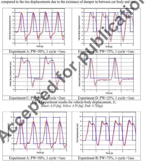
Experiment results are shown in Fig. 4 and 5. Blue lines represent the road disturbance input. Fig.4 shows car body displacement (represented by y-axis) and it represents the ride quality of a
vehicle. By referring to all four results, it can be observed that heavier Ms undershoots greater when
the movement direction is the same as gravitational direction (i.e. downwards). Also, the peak
magnitude decreases as the Ms increases because large gravitational force will restrict the oscillation
of system. As a conclusion, the greater the vehicle body mass, the greater the gravitational pull exert on the vehicle body mass thus creates greater undershoots and lower overshoots.
Fig. 5 shows tire displacement responses that represents the car handling of a vehicle. It is observed that Fig.5 responses are almost similar to Fig.4. The car body displacements are smoother compared to the tire displacements due to the existance of damper in between car body and tire.
0 1 2 3 4
-6 -4 -2 0 2 4 6 8 10 12 V ehi cl e B ody D is pl ac em ent [c m ] Time [s]
0 1 2 3 4
-6 -4 -2 0 2 4 6 8 10 12 V ehi cl e B ody D is pl ac em ent [c m ] Time [s] p
Experiment A: PW=50%, 1 cycle =1sec Experiment B: PW=75%, 1 cycle =1sec
0 1 2 3 4
-6 -4 -2 0 2 4 6 8 10 12 p [ ] V ehi cl e B ody D is pl ac em ent [c m ] Time [s]
0 1 2 3 4
-6 -4 -2 0 2 4 6 8 10 12 V ehi cl e B ody D is pl ac em ent [c m ] Time [s]
Experiment C: PW=50%, 1 cycle =2sec Experiment D: PW=25%, 1 cycle =1sec
Fig. 4 Experiment results for vehicle body displacement, Xs
(Black: 4.29 [kg], Yellow: 4.59 [kg], Pink: 4.79[kg])
0 1 2 3 4
-2 0 2 4 6 8 10 12 T ire D is pl ac em ent [c m ] Time [s]
0 1 2 3 4
-4 -2 0 2 4 6 8 10 12 p [ ] T ire D is pl ac em ent [c m ] Time [s]
Experiment A: PW=50%, 1 cycle =1sec Experiment B: PW=75%, 1 cycle =1sec
A
cc
ep
te
d
fo
r
pu
bl
ic
0 1 2 3 4 -4
-2 0 2 4 6 8 10 12
p
[
]
T
ire D
is
pl
ac
em
ent
[c
m
]
Time [s]
0 1 2 3 4
-4 -2 0 2 4 6 8 10 12
T
ire D
is
pl
ac
em
ent
[c
m
]
Time [s]
Experiment C: PW=50%, 1 cycle =2sec Experiment D: PW=25%, 1 cycle =1sec
Fig. 5 Experiment results for tire displacement, Xus
(Black: 4.29 [kg], Yellow: 4.59 [kg], Pink: 4.79[kg])
The damper is used to absorb the shock from the road and therefore regulate the oscillation of the vehicle body. This will help to make the driving experience more comfortable. Other than that, the tire position is always able to return to its original position as compared to the car body position
after any disturbances. This is because tire spring constant kt is stiffer than suspension spring
constant ks. The less stiffer suspension spring also causes the damper not able to fully retract back to
its original position. For a better performance, the suspension system spring constant need to be designed higher. This also could help to reduce the oscillation amplitude of the car body during the disturbance. This is crucial in helping to increase riding comfort during the road disturbances.
Figure 6 shows the simulation and experimental results respectively. It can be observed that the oscillation of simulation result are higher and larger than experimental result. This is because simulation is linearized system and friction is not taken as a parameter in the simulations. Experiment in real time is nonlinear system because friction exists during experiments. Basically, friction in real plant is nonlinear parameter. Therefore, friction in plant will change its value based on the surrounding conditions.
(a) Vehicle body displacement (b)Tire displacement
Fig. 6 Simulation and experiment results (pink & green lines respectively)
Conclusion
This paper has described a prototype of passive suspension. Via this prototype, the students are able to gain experience in observing system characteristics particularly suspension system which deals with spring and damping characteristics. To further improve this prototype, it is recommended to have more accurate displacement sensors replacing IR-sensor. Besides that, the used bearings are suggested to be replaced with stainless and frictionless bearings as the friction experienced by the plates are too high during the experiments. Also, in order to introduce more disturbance input signals, the pneumatic cylinder has to be changed to a pneumatic actuator that could generate different amplitude signals and capable of generating sinusoidal signal waveforms. In parallel to these corrective actions, the prototype will be equipped with an active actuator to perform control actions on the prototype particularly on the car body displacement.
A
cc
ep
te
d
fo
r
pu
bl
ic
References
[1] L. Kong, X. Zhao, and B. Qi, “Study on Semi-Active Suspension System of Tracked Vehicle
Based on Variable Universe Fuzzy Control”, IEEE International Conference on
Mechatronics and Automation, pp. 2276-2280, 2011.
[2] A. Agharkakli, G. S. Sabet, and A. Barouz, “Simulation and Analysis of Passive and Active
Suspension System Using Quarter Car Model for Different Road Profile”, International
Journal of Engineering Trends and Technology, Volume31Issue5, pp. 636-644, 2012.
[3] L. J. Yue, C. Y. Tang, and H. Li, “Research on Vehicle Suspension Systems based on Fuzzy
Logic Control”, IEEE Intl. Conf. on Automation and Logistics, pp. 1817-1821, 2008.
[4] Y. Zheng, “Research on Fuzzy Logic Control of Vehicle Suspension System”, International
Conference on Mechenic Automation & Control Engineering (MACE), pp. 307-310, 2010.
[5] Winfred K.N.A, Dion R.T, Scott C.J, Jon B, Dale G, George W.A, Ron R, Jixiang S, Scott
G, and Li C, “Development and Control of a Prototype Pneumatic Active Suspension
System”, IEEE Transactions on Education, Vol.45, No.1, 2002.
A
cc
ep
te
d
fo
r
pu
bl
ic