UNIVERSITI TEKNIKAL MALAYSIA MELAKA
MODELLING AND SIMULATION OF ROTARY INVERTED
PENDULUM DESIGN
This report submitted in accordance with requirement of the Universiti Teknikal Malaysia Melaka (UTeM) for the Bachelor’s Degree in Electrical Engineering
Technology (Industrial Power) (Hons.)
by
NURUL SUHAILAH BINTI SAADON
B071110261
921224-01-6148
UNIVERSITI TEKNIKAL MALAYSIA MELAKA
BORANG PENGESAHAN STATUS LAPORAN PROJEK SARJANA MUDA
TAJUK: Modelling and Simulation of Rotary Inverted Pendulum Design
SESI PENGAJIAN: 2014/2015 Semester 1 SayaNURUL SUHAILAH BINTI SAADON
Mengaku membenarkan Laporan PSM ini disimpan di Perpustakaan Universiti Teknikal Malaysia Melaka (UTeM) dengan syarat-syarat kegunaan seperti berikut:
1. Laporan PSM adalah hak milik Universiti Teknikal Malaysia Melaka dan penulis. 2. Perpustakaan Universiti Teknikal Malaysia Melaka dibenarkan membuat salinan
untuk tujuan pengajian sahaja dengan izin penulis.
3. Perpustakaan dibenarkan membuat salinan laporan PSM ini sebagai bahan pertukaran antara institusi pengajian tinggi. atau kepentingan Malaysia sebagaimana yang termaktub dalam AKTA RAHSIA RASMI 1972)
(Mengandungi maklumat TERHAD yang telah ditentukan oleh organisasi/badan di mana penyelidikan dijalankan)
Alamat Tetap:
DECLARATION
I hereby, declared this report entitled “MODELLING AND SIMULATION OF ROTARY INVERTED PENDULUM DESIGN” is the results of my own research
except as cited in references.
Signature :
Author’s Name : NURUL SUHAILAH BINTI SAADON
APPROVAL
This report is submitted to the Faculty of Engineering Technology of UTeM as a partial fulfillment of the requirements for the degree of Bachelor of Engineering Technology (Industrial Power) (Hons.). The member of the supervisory is as follow:
……… (Mr. Khalil Azha bin Mohd Annuar)
ABSTRAK
Sistem bandul songsang ( inverted pendulum ) telah menjadi salah satu cabaran yang
paling mencabar walaupun ia adalah sistem yang menarik dalam era ini. Sistem bandul songsang adalah sistem klasik yang termasuk dalam bidang kejuruteraan dengan ciri-ciri yang merupakan sistem yang tidak stabil, pembolehubah dan sistem bukan linear. Struktur sistem bandul songsang ini terdiri daripada bentuk rod menegak, lengan mendatar dan pengekod yang akan mendorong bandul untuk berputar . Projek ini bertujuan untuk mendapatkan pemodelan matematik sistem bandul songsang dan menggunakansesuatu kawalan untuk mengawal sistem ini. Model matematik boleh diperolehi dengan pengiraan model sistem bandul terbalik dengan menggunakan
persamaan Euler’s untuk melaksanakan persamaan ruang keadaan. Oleh itu, pengawal
penempatan kutub adalah dicadangkan dalam projek ini untuk mengawal selia sistem bandul songsang dalam kedudukan menegak. Terbitan matematik membuktikan bahawa pengawal direka diperlukan untuk menstabilkan sistem bandul terbalik . Kajian simulasi dijalankan untuk membuktikan keberkesanan pengawal yang direka dan hasilnya menunjukkan bahawa pengawal itu berupaya mengekalkan bandul dalam kedudukan terbalik yang stabil pada nilai yang dikehendaki.
ABSTRACT
Rotary Inverted Pendulum System (RIPS) has become one of the most challenging task even it is an interesting system in this era. RIPS is a classical system that includes in this engineering system field with characteristics which is an unstable system, multi-variables and non-linear system. The stucture of this inverted pendulum system is made up of a vertical pendulum rod, a horizontal arm and an encoder which will drives the pendulum to rotate. This project intends to obtain a mathematical modeling for the RIPS and to develop the controller for the system. The mathematical model can be obtained by deriving the model of inverted pendulum system by using Euler’s equation to perform state space equation. Therefore, the Pole Placement controller is proposed in this project to regulate the RIPS to drive it in upright position. The mathematical derivations proved that the designed controller is required to stabilize the inverted pendulum system. Simulation study is performed to prove the effectiveness of the designed controller and the result shows that the controller is capable to maintain the pendulum in the stable inverted position at the desired value of parameters.
DEDICATION
For my beloved father (Saadon bin Abd Salam) and my mother (Roslin binti Hj. Baba) for their endless support through the entire time
My sisters (Salina binti Saadon, Norhaslinda binti Saadon, Siti Hajjar binti Saadon, Intan Mastura binti Saadon and Syazwani binti Saadon) and brothers in law that always gave
advices and support to me throughout my life especially in university
My special friend, Habibullah bin Ibrahim that always gave me strength to complete my Final Year Project.
ACKNOWLEDGEMENT
Bismillahirrahmanirrahim. In the name of Allah, The Most Gracious and The Most Merciful. Alhamdulillah for all the strength and His willing, I finally finished completing my thesis for Final Year Project.
I would like to thank my supervisor, Mr. Khalil Azha bin Mohd Annuar who always gave me advices and guidance throughout the entire project. It will not be easy for me to complete this Final Year Project without his guidance.
My outmost thanks goes to my father (Hj. Saadon bin Hj. Abd Salam) and my mother (Hjh. Roslin binti Hj. Baba), my sisters especially Intan Mastura binti Hj. Saadon for always giving me ideas throughout my research. My special friend, Habibullah bin Ibrahim for always giving me support and strength.
To all my classmates, thank you so much for the continual support and encouragement. Not to forget, the memories we shared together throughout our study time that I will not forget. Thank you so much.
CHAPTER 3 : METHODOLOGY 15
3.1 Research 15
3.2 Mathematical Modelling of Rotary Inverted Pendulum 16
3.2.1 State Space Equation 16
3.3 Pole Placement Controller Design 22
CHAPTER 4 : RESULT & DISCUSSION 25
4.1 System without controller 25
4.2 System with Pole Placement Controller 27
4.3 System with Pole Placement Controller with different parameters of rotary
inverted pendulum 30
CHAPTER 5 : CONCLUSION & RECOMMENDATIONS 31
5.1 Conclusion 31
5.2 Recommendations 32
5.3 Project Potential 33
REFERENCES 34
APPENDICES
Appendix A Appendix B
LIST OF TABLES
2.1 3 types of controller 8
3.1 Equations of velocity of pendulum centre of mass (B) 18
3.2 Equations of the speed of point B 18
3.3 Equations of acceleration of the point B 18
3.4 Parameters used to calculate values of A, B, C, D, E and F 21
3.5 Parameters of state space equation 22
LIST OF FIGURES
1.1 Rotary Inverted Pendulum 2
2.1 Inverted Pendulum on a Cart 11
2.2 Rotary Inverted Pendulum 11
2.3 Clock Pendulum 12
2.4 Machine Crane System 13
2.5 Pendulum Ride 14
3.1 Block diagram representation of state space equation 17 3.2 Free Body Diagram of rotary inverted pendulum 17
3.3 State space eqaution 20
3.4 System with state feedback of Pole Placement controller 23
4.1 Simulation of Rotary Inverted Pendulum System 25 4.2 Graph of step response of rotary inverted pendulum system 26
4.3 Simulation of Pole Placement controller 27
4.4 Step response for Rotary Inverted Pendulum system 28 4.5 Simulation of rotary inverted pendulum with Pole Placement
controller
28
4.6 Step response of rotary inverted pendulum 29
4.7 Step response of rotary inverted pendulum comparison 30
LIST OF ABBREVIATIONS
DC - Direct Current
PID - Proportional Integral Derivative LQR - Linear Quadratic Regulator FLC - Fuzzy Logic Controller
RIPS - Rotary Inverted Pendulum System MATLAB - Matrix Laboratory Software
LIST OF SYMBOLS
Ts - SettlingTime
Tr - Rise Time
Jeq - Inertia of the arm
Beq - Viscous damping coefficient
Rm - Armature resistance
G - Gravity
L - Length of pendulum
r - Length of arm
m - Mass of the pendulum
ma - Mass of the pendulum arm
kb - Torque of motor
α - Angle of pendulum attached to pendulum arm
� - Angle of pendulum arm attached to motor shaft
B - Pendulum centre of mass
O - Rotational motion about origin of arm
In this Chapter 1, the background of the project study, objectives of the project, the project scope and the problem statement will be discussed.
1.1 Background
Nowadays, there are many modern control systems that can be used in many applications. Some of the control systems, for example, non-linear control, optimal control, and adaptive control. However, all these controls are difficult to be implemented since there are many sequences that need to be used in designing the controller. A set up of input needs to be analyzed and also the output of the system to achieve a good feedback from the signals.
An inverted pendulum system is one of the control systems that is the simplest problem but difficult to balance it upright vertical position since the pendulum would be naturally falling down from the vertical upright position. In solution, designing the Pole Placement controller where mathematical modelling is needed to achieve an accurate feedback is required. Thus, in this project, Matlab / Simulink is to be used in controlling the inverted pendulum by mathematical modelling of Pole Placement controller.
INTRODUCTION
CHAPTER 1
Figure 1.1 shows the rotary inverted pendulum which consists of a rigid rod (pendulum) that is rotate in vertical plane where have been attached to a pivot arm that is mounted on the shaft of the servo motor. The pivot arm itself will rotate in horizontal plane and the pendulum will always hanging downwards. This type of pendulum, which is rotary inverted pendulum is an unstable system and required a controller to be actively balanced in order to remain the pendulum in upright vertical position.
Figure 1.1 : Rotary Inverted Pendulum
1.2 Objectives
There are 3 objectives to be achieved in this project :
i. To derive the mathematical model of the rotary inverted pendulum system in state space equation
ii. To design the Pole Placement for rotary inverted pendulum system
iii. To simulate the mathematical model to perform simulation with and without Pole Placement controller in Matlab / Simulink
1.3 Project Scopes
This project requires some scopes to be pursued to achieve the objectives. These are the scopes of the project which are to :
i. Modelling the system to obtain the mathematical model for rotary inverted pendulum system
ii. The Pole Placement controller need to be developed after the mathematical model have been derive
iii. The pendulum angle will be shown by the output of the simulation which performed by Matlab / Simulink
1.4 Problem Statement
Inverted pendulum is one of the fundamental problem in this field control theory. But when it comes to rotating the pendulum to maintain in vertical upright position, it is quite difficult since it is naturally unstable and has an open loop configuration. Thus, a controller is needed to be designed and to be simulated successfully to drive the pendulum in order to swing up the pendulum.
1.5 Outline of thesis
This thesis consists of 5 chapters. In first chapter, the discussion about the background of the rotary inverted pendulum system which included also the objectives of the project, scope of the project and problem statement in completing the project.
Chapter 2 will focused more on the literature review that have been done by referring and research on journal, thesis, internet based on the rotary inverted pendulum system.
Chapter 3 discussed on the mathematical modelling of the rotary inverted pendulum system and methodology in completing this project.
The result and discussion based on the output of the project will be discussed more in Chapter 4. The pole placement controller can be considered as the good controller in order to swing up the pendulum and can give stabilization to the pendulum
In Chapter 5, the conclusion of this project will be explained as well as the suggestion and recommendation in order to improve this project for future work or development.
In this Chapter 2, a literature review will be discussed after research has been done. A literature review can be stated as a discussion on the information in many ways to complete the project.
2.1 Inverted Pendulum System
Pendulum can be described as a system in a control field theory. An inverted pendulum includes a pendulum rod in vertical, a horizontal pendulum arm, a motor and an encoder. This system was developed by Stephensen about 100 years ago that the controller is needed in order to achieve a stabilization for inverted pendulum in remain upright. The elasticity of the inverted pendulum was studied by Chao under the expectation of beam. This system is widely used in this control engineering that was also applied in many industries such as balancing a broom with only one hand, by launching the rocket from the ground and to stable the arm of robot. Thus, there were many studies on doing a research of the inverted pendulum system that are still in progress of carrying it all over the world. (Tang Jiali Ren Gexue, 2009)
LITERATURE REVIEW
CHAPTER 2
2.1.1 Inverted Pendulum Configuration
M. Amin Sharifi K. (2010) states, the arrangement of inverted pendulum consists many types of designation in this control field. There were two aspects in this arrangement of inverted pendulum which are the method of actuation and the number of degrees of freedom. There are two factors that can be considered are linear and rotary of inverted pendulum system for the method of actuation. The input of the system of linear inverted pendulum is force, F and for rotary inverted pendulum is torque, T. For the linear arrangement of inverted pendulum, the movement of the cart is in horizontal that can be controlled by motor where the pendulum is connected to the cart. The rotary inverted pendulum consists of horizontal arm that attached to the upper surface of motor and also at the end of encoder.
The rotary inverted pendulum system is attached to the servo motor drives where the position of angular can be measure by the use of encoder which act as sensor. There are two types of encoder been used where the pendulum is attached to it, thus it will measures the angle of pendulum. The simulation then will be done by using Matlab / Simulink based real time software. There were also two types of position of the pendulum, stable and unstable. The position of pendulum in vertical upright position shows that the pendulum is in unstable and when is vertically down, the position of the pendulum is in stable position. (Md. Akhtaruzzaman and A.A Shafie, 2010).
2.2 Controller Design
The important factor of the inverted pendulum system was to develop the control techniques to make the pendulum in upright position and to maintain the stabilization of the system. There were two techniques in designing the controller which are by using Linear Quadratic Regulator (LQR) controller and Proportional, Integral and Derivative (PID) controller. The function of this controller is to develop linear model to stabilize the position of inverted pendulum in upright position. In this paper, the method to derive the LQR controller was by using the Algebraic Ricatti Equation and for PID controller, the Ziegler Nicholas Tuning method was used. (M. Amin Sharifi K, 2010).
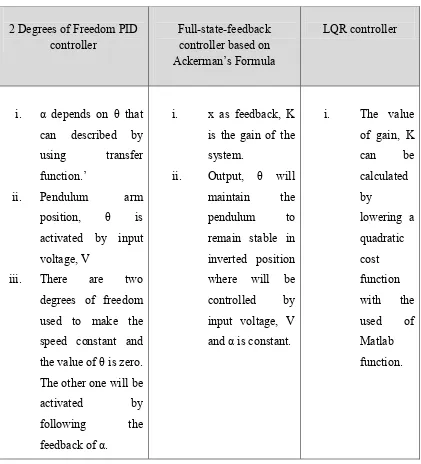
Meanwhile, there were 3 design of controllers technique which comprising in this journal, (Md Akhtaruzzaman and A.A Shafie, 2010). The state space equation is required by deriving the mathematical modelling of the rotary inverted pendulum where the inverted pendulum system is attached to a rotary servo plant motor and simulation by MATLAB. The α represents the pendulum angle and � represents the pendulum arm.
Table 2.1 : 3 types of controller
2 Degrees of Freedom PID
controller Full-state-feedback controller based on Ackerman’s Formula
Furthermore, the rotary inverted pendulum system can also be controlled by a control technique which is state-feedback control. The pendulum requires to be balanced to upright position with no zero initial and the signal from the input has to be recompensed. In this journal states that the linear state feedback controller was chosen as it can control the certain degrees of freedom at one time. To get more balance, there were two appended problem while driving the pendulum upright position which are by using a swing-up controller and a switching mechanism. This
will results the pendulum to be intercepts to achieve stabilization. (Slavska Jadlovska and Jan Sarnovsky, 2012).
Baili Zhang (2011), three methods used to design the controller of the inverted pendulum, where for PID controller, it depends on the parameter of the Proportion, P, Integral, I and Derivative, D. For this method, it used transfer function that can be achieved by the state space equation and developed by using double closed loop control. For the state feedback controller, there were used of state space equation for the plant model and it will directly feedback to the input signal where the value of gain proportion link, K can be obtained. Lastly, the Linear Quadratic Regulator, LQR, the linear state that is to be formed can be used in state space equation. The used of matrix equation shows that weighting matrix, R and Q are for balancing state variable and also input variable, and the value of P can be obtained by using Riccati equation. Therefore, value of K can be formed using this formula : K = (�−1)(��) (P).
In this paper, there were two methods of control method to control the inverted pendulum system which is non-linear system. The first control method is PID control that considered the PID controller for the pendulum and also the cart used. The controller has been designed for these two loops of the control system. The equations of this controller consists of :
�
(
�
)
1= 1 +
�
��e
0(
�
) + K
ip ∫ eo+
�
�������(�)
�
(
�
)
1=
�
���
�(
�
) + K
ic∫
�
�+�
�� ���(�)��
where, �0(�) and��(�) are angle error and cart position error.
Even the parameters of the controller can be changed, it will also affects both angle of pendulum and cart position which make the tuning tedious. Thus, there were trial and error has been done in order to tune the parameters and the performance can be shown in the Matlab / Simulink model to be the optimal. The other controller that has been used was optimal control using Linear Quadratic Regulator (LQR) which can result to the better performance with respect to some criteria. This controller is to find the control signals that will activate the process that required to the some of requirements and also can maximize or minimize the criteria of performance. (Lal Bahadur Prasad, 2011).
2.2.1 Inverted Pendulum on a Cart
One type of inverted pendulum is the inverted pendulum that is connected on a cart. From the base apparatus itself, it consists of horizontal plane where there is a particular sled that has been constrained to one axis. There is no weight of the rod which can be assumed as weightless. By using M, it shows the mass of the cart and m as the point mass at the end of the rod which has l as a length. From it pivot point, this inverted pendulum consists of its centre of mass. This system is usually found in this control system field of study as it is very popular and student can easily get information about this system. So as rotary inverted pendulum, this inverted pendulum on a cart is non-linear and unstable system that includes one input signal and many output signals. In balancing the pendulum that is vertically on a driven motor cart, the control design is important and can be used such as PID controller, LQR controller, Fuzzy Logic Controller and genetic algorithms. (Andrew Hovingh and Matt Roon, 2005)