INTEGRATED FILLING AND CAPPING SYSTEM IN
BOTTLING OPERATION
AZIZUL BIN AHMAD
UNIVERSITI TEKNIKAL MALAYSIA MELAKA
Integrated Filling and Capping System in Bottling
Operation
Thesis submitted in accordance with the partial requirements of the Universiti Teknikal Malaysia Melaka for the
Bachelor of Manufacturing Engineering (Robotics and Automation)
By
Azizul Bin Ahmad
Faculty of Manufacturing Engineering
UTeM Library (Pind.1/2007)
UNIVERSITI TEKNIKAL M ALAYSIA M ELAKA
BORANG PENGESAHAN STATUS LAPORAN PSM
JUDUL:
“ INTEGRATED FILLING AND CAPPING SYSTEM IN BOTTLING OPERATION”
SESI PENGAJIAN:
“ SEMESTER 2 2007/ 2008”
Saya AZIZUL BIN AHMAD
Mengaku membenarkan laporan PSM / t esis (Sarj ana/ Dokt or Falsaf ah) ini disimpan di Perpust akaan Universit i Teknikal Malaysia Melaka (UTeM) dengan syarat -syarat kegunaan sepert i berikut :
1. Laporan PSM / t esis adalah hak milik Universit i Teknikal Malaysia Melaka dan
penulis.
2. Perpust akaan Universit i Teknikal Malaysia Melaka dibenarkan membuat salinan
unt uk t uj uan pengaj ian sahaj a dengan izin penulis.
3. Perpust akaan dibenarkan membuat salinan laporan PSM / t esis ini sebagai bahan
i
DECLARATION
I hereby, declared this thesis entitled “Integrated Filling and Capping System in Bottling Operation” is the results of my own research except as cited in references.
Signature : ………
Author’s Name : ………
ii
APPROVAL
This PSM submitted to the senate of UTeM and has been as partial fulfillment of the requirements for the degree of Bachelor of Manufacturing Engineering (Robotics and
Automation). The members of the supervisory committee are as follow:
……… (En Shariman Bin Abdullah)
iii
ABSTRACT
iv
ABSTRAK
v
DEDICATION
vi
ACKNOWLEDGEMENT
Alhamdulillah, I thank Allah S.W.T, The Most Beneficent and The Most Merciful, for his guidance and for granting me knowledge and patience throughout doing this project. I would like to take this opportunity here to express my deepest gratitude and highest appreciation to my supervisor; En Shariman Abdullah for their strong support, encourage and guidance during my Final Year Project 2 during this semester.
As we know the scope of this final project is to train student on real life working environment that include learning something new and training what we had learn before. I had learned so many things and the most important thing is about the objective of the project for my future working.
Thanks for everything that giving me the opportunity to learn in here, especially for all that created my characteristic on my ambition to be an engineer with fully responsibility on work.. I also want to extend my thanks to those who helped me, especially to all lecture from Faculty of Manufacturing for their brilliant ideas, comments and advices.
TABLE OF CONTENTS
Table of Contents vii
List of Figures xi
List of Tables xiii
1. INTRODUCTION 1
1.1General Introduction 1
1.2Problem Statements 2
1.3Objectives of Project 3
1.4Scope of Project 3
2. LITERATURES REVIEW 5
2.1 Introduction 5
2.2 Techniques Operation Filling System 5
2.2.1 Overflow Filler Selection Guide 5
2.2.2 Peristaltic Filler Selection Guide 7
2.2.3 Piston Filler Selection Guide 8
2.2.4 Net Weight Filler Selection Guide 9
2.3 Techniques Operation Capping System 11
2.3.1 Computorque Automatic Capping System 11
2.3.2 Chuck Capping System 13
2.4 Custom Conveyor System 18
2.4.1 About Conveyor system 18
2.4.2 Sanitary Conveyor 18
2.4.3 Chemical Resistant Conveyor 19
2.4.4 Heat Resistant Conveyor 19
2.4.5 Material Handling Conveyor 20
2.4.6 Hazardous Location Conveyor 20
2.5 Motor Selection 21
2.5.6 Single-phase Motor 27
2.6 Sensor 28
3.3 Methodology Flow Chart 34
3.4 Conceptual Design 35
3.4.1 Filling Operation Concept 35
3.4.2 Capping Operation Concept 36
3.5 Identify Project Requirement 38
3.5.1 Motor Selection 38
3.5.2 Sensor Requirement 39
3.5.3 Material Selection 39
3.5.4 Conveyor Classification 39
3.6 Develop, Assembly and Testing 40
3.7 Process Flowchart 41
3.7.1 Flowchart Filling System 41
3.7.2 Flowchart Capping System 42
3.8 Experimental Method 43
4.2.3 Capping Operation 45
4.2.4 Conveyor System 46
4.3 Finalize 47
4.3.1 Basic Calculation 47
4.4 Filling Time Required To Complete The Filled In The Bottle 48 4.5 Capping Time Required To Complete The Capped To The Bottle 49
5. DISCUSSIONS 50
5.1 Introduction 50
5.2 Identifying the Result 51
5.2.1 Control Impact of effiency and Net Production 51
5.3 Improving the Results 53
6. CONCLUSION 54
REFERENCES
LIST OF FIGURES
2.2.1a Liquid transfer from tank to bottle 6
2.2.1b Basic sonic liquid level sensor ± Bogue Electric Manufacturing Company
7
2.2.2a Peristaltic Filler system 8
2.2.3 Piston filler system 9
2.2.4 Net Weight Filler system 10
2.3.1a Computorque Automatic Inline Capping Machine 11
2.3.1b Backup detection 12
2.3.1c Dual Cap Handling Capability 12
2.3.2a Robocap Automatic Chuck Capping Machine 13
2.3.2b Compact Ergonomic Design 14
2.3.3a Automatic Snapcap Capping Machine 15
2.3.3b Unique Roller Applicator 16
2.3.3c Automatic Vertical Cap Placing Machine 17
2.4.2 Sanitary Conveyor 18
2.4.3 Chemical Resistant Conveyor 19
2.4.4 Heat Resistant Conveyor 19
2.4.5 Material Handling Conveyor 20
2.4.6 Hazardous Location Conveyor 20
2.5.1 Basic working principle of a hybrid stepper motor with 12 steps per revolution
22
2.5.3 Commutating Plane 24
2.5.5a Rotor 25
2.5.5b Stator 26
2.6.1 Limit Switch 28
3.4.1a Basic sonic liquid level sensor ± Bogue Electric 35
3.4.2 Capping operation system 37
3.4.3 Conveyor 37
4.2.2 Filling Operation 45
4.2.3 Capping Operation 45
LIST OF TABLES
2.7 Material comparison 31
3.3 Methodology flow chart 34
3.5.1 Table– DC Motor classification 38
3.5.4 Table– Conveyor classification 39
3.7.1 Flowchart Filling System 41
3.7.2 Flowchart Capping System 42
3.8 Experimental Methods 43
1
CHAPTER 1
INTRODUCTION.
1.1 General Introduction.
Filling and capping system is the most commonly system that have been used in industrial machinery to produce product such as sauces, syrups, light gels and shampoos, foamy cleansers and chemicals, water and beverages. It also used to produce heavy sauces, salsas, salad dressings, cosmetic creams, heavy shampoo, gels, and conditioners, paste cleaners and waxes, adhesives, heavy oils and lubricants.
For this project, I have been given a task to develop Integrated Filling and Capping System in Bottling Operation. This project has 2 tasks, filling system and capping system. Filling is usually the aspect of filling the bottle with the product such as the example that has been given forward.
In filling system, the equipment that will be use is pipe, nozzle, conveyor, reservoir and piston system. There are many type of machine system of filling operation such as Overflow Fillers, Servo Pump Fillers, Peristaltic Fillers, Time Gravity Fillers and Piston Fillers. Bottle filling means suitable for filling a liquid with contain in a bowl at super atmospheric pressure, comprising a float valve which establish a liquid level therein.
2 filling. The fill tube are the shaft of respective double acting fluid pressure operated cylinder of simple construction which position a port in the fill tube upper wall extremes within the fill tank confines or within pressure sealing cylinder end bushing to define respective open and closed fill valve condition.
Usually, capping is the most difficult aspect of a packaging line for several reasons. Sometimes the range of geometry and size of caps and bottles is so wide that the capping machine components become expensive or the platform of the machine is not suitable for all sizes in the range. Sometimes the bottle and cap combination are not ideal with the threads of the bottle being in conflict with the threads of the cap. Sometimes, caps can only be placed vertically on the container which increases the capital cost of the machinery. A bottle cap positioning apparatus positions bottle caps beneath the orbiting capping heads of a rotary bottle capping machine for pick up. A cap feeder places the cap on a semi circular pick up path directly under the orbital path of the capping heads. An endless belt is supported on a pair of pulleys and orbits around a guide block. The guide block has a convex surface that pushed the belt outward to parallel the pick up path. Gears drive the pulleys and synchronize the endless belt with the capping heads to reduce factory floor space requirements and worker exposure to moving parts.
1.2 Problem Statement
3
1.3 Objective of Project
The main objectives of this project are:
a) To develop filling machine from the overflow piston system which is low cost and maintenance but it can access high production rate and efficiency and operate with high accuracy and precision.
b) To develop capping machine with the new capping system which is low cost and maintenance but it can access high production rate and efficiency and operate with high accuracy and precision.
c) To analyze the piston systems performance for the filling operation including the efficiency and the output stability.
d) To analyze the performance for the capping operation including the efficiency and the output stability.
e) To design and fabricate the filling and capping machine with the suitable material selection in order for manufacturing assembly of the system that has the effectiveness with low cost maintenance.
1.4 Scope of Project
The project emphasis on designing a model of filling and capping operation system which using the same operation and to reduce the cost. Then, later on in the project, a concept of the system will be fabricated based on the design. The design that will be fabricated are based from the bottle that to be used. Finally, test and analysis will be carried out on the developed system. This is the related scope of the project:-
Working space:
a) Transportation conveyor.
b) Transport the bottles from filling workstation to capping workstation. c) Only one line or path to transport the bottles.
4 Filling workstation:
a) Reservoir to load the liquid.
b) Pipe to transfer the liquid to mechanical pusher piston system. c) Overflow filler piston system.
d) Nozzle exits the liquid.
e) Mechanical pusher piston to push the load through inside the bottle. f) DC Driven motor to move the piston inverse and forward.
Capping machine:
a) DC driven motor to rotate the cap until tight. b) Roller to support the cap.
c) Aluminum hollows to holder the cap.
d) Timers relay to estimate the running time of driven motor.
Conveyor system:
a) Belt to carry the bottle. b) Roller to move the belt.
c) DC driven motor to operate the roller.
Material:
5
CHAPTER 2
LITERATURE REVIEW
2.1 Introduction
The Filling and Capping Bottling Operation system is using three main parts that are filling process, capping process and conveyor system. To understand this project, some research has been done throughout making this project to be successful. The research included the type of motor, the conveyor system, system operation, material and other more that required developing a Integrated Filling and Capping System in Bottling Operation.
2.2 Techniques Operation Filling System 2.2.1 Overflow Filler Selection Guide.
Application:
This type of filler is best suited for liquids with low to medium viscosity. Liquids with solid particulates not exceeding 1/16" can also be filled. Note that overflow fillers are the machine of choice in handling very foamy products at higher speeds.
Examples:
6
Advantages:
High performance, easy to clean, easy to operate, expandable at low cost. Offers greatest flexibility at lowest cost.
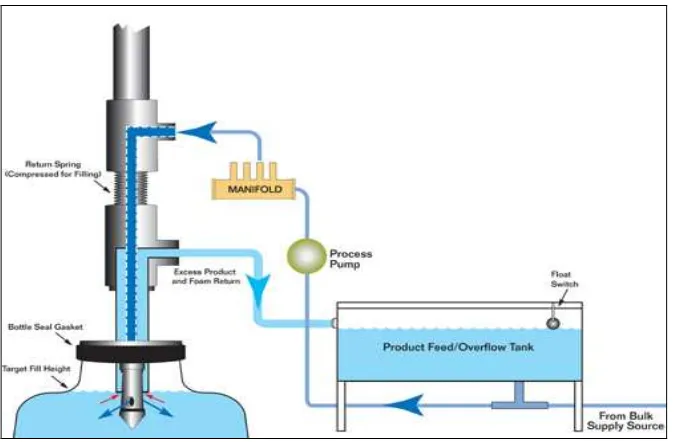
The supply side of a two part nozzle is used to pump product into the container. When the container fills up to the target fill height, the excess product and foam is forced out of the container via the return side to the original product source tank.
Figure 2.2.1a – Liquid transfer from tank to bottle
Elements of a Bottling Process
7 the bottle has reached the end of the spout, therefore, setting the level. The filling valve is then set mechanically closed by the `closing control system' which operates the throttle. After filling, the bottles are then taken by a star which positions them under the crowner or capper where they are sealed. Another star positioned at the end of the capper picks the bottles and places them on the conveyor belt, where they are again sprayed with water on the outside, then transported to the labeler.
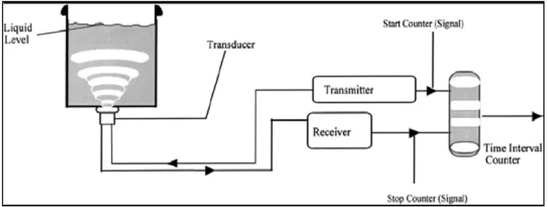
Figure 2.2.1b - Basic sonic liquid level sensor ± Bogue Electric Manufacturing Company
2.2.2 Peristaltic Filler Selection Guide.
Application:
Specifically designed for high value, small volume fills at very high accuracy. Suitable for aqueous and other light viscosity product
Examples:
Pharmaceutical preparations, fragrances, essential oils, reagents, inks, dyes, and specialty chemicals.
Advantages:
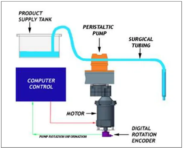
8 The peristaltic pump makes intermittent contact on only the outside of the product tubing so that the product only touches the inside of the tubing. The filler's master computer independently tracks the speed of rotations of the peristaltic pump head so that it knows precisely how much product has been delivered. When the target fill volume is reached, the pump stops and the remaining product fluid do not drip out due to pipette action. The computer stores all fill parameters in memory for fast changeovers.
Figure 2.2.2a - Peristaltic Filler system
2.2.3 Piston Filler Selection Guide.
Application:
This type of filler is best suited for viscous products that are paste, semi paste, or chunky with large particulates. These fillers are built to meet food grade standards and can also handle various chemical applications.
Examples: