Characteristics of Impingement Diesel Spray
Adhesion on a Flat Wall
A THESIS
Submitted by
MOHD ZAID BIN AKOP
In partial fulfillment of the requirements for the award of the Degree of
DOCTOR OF PHILOSOPHY IN
MECHANICAL SYSTEM ENGINEERING
Under the guidance of
PROFESSOR MASATAKA ARAI, Ph. D. Eng.
DIVISION OF MECHANICAL SCIENCE AND TECHNOLOGY
GUNMA UNIVERSITY JAPAN
i
Acknowledgement
Special thanks to my supervisor Professor Dr. Masataka Arai for his great
guidance and support. Without his support this study could not have been done
properly.
I am gratefully acknowledges the research support from Dr. Tomohiko
Furuhata, Dr. Yoshio Zama, Dr. Masahiro Saito and Mr. Goro Ogiwara for their
advice and support during my study. My great appreciation also goes to other
members of our diesel spray group, Mr. Wataru Ochiai, Mr. Kazuma Sugawara,
Mr. Jun Takahashi and Mr. Yuta Kobuchi for their help in setting up and collecting
data of this work.
I would like to forward my gratitude to Universiti Teknikal Malaysia Melaka
(UTeM) and the Malaysian Government for permission to pursue Ph.D. degree and
providing the financial support.
Finally, I also would like to thank to my mother Noraini Ahmad, my beloved
wife Marianee Sa’adon and my little daughter and son, Aimee Hadirah and Aqeef
ii
Declaration
I hereby declare that this submission is my own work and that, to the best of
my knowledge and belief, it contains no material previously published or written
by another person, nor material which has been accepted for the award of any other
degree of the university or other institute of higher learning, except where due
acknowledgement has been made in the text.
Signature:
Name: Mohd Zaid bin Akop
Student No.: 11812272
Date:
iii
Impinging diesel spray and its research problem
1.1 Introduction 1
1.2 General views of diesel spray 1
1.2.1 Diesel sprays in the combustion process 1 1.2.2 Wall impingement and its spray-wall interaction 5
(a) Wall impingement 5
(b) Impingement spray behavior 6 (c) Impingement droplet and its Weber number 10
(d) Spray-wall interaction 12
1.2.3 Adhered fuel film and mass of impingement spray 14
(a) Adhered fuel film 14
(b) Adhered fuel mass and fuel film thickness 17 1.2.4 Impinging spray droplet and mean diameter of spray 21 1.2.5 Injection pressure and gas density surroundings of diesel spray 24 1.2.6 Other characteristics of diesel spray 27 1.2.7 Non-evaporated and evaporated spray 29
1.3 Purpose of this research study 30
1.3.1 Overview of recent studies 30
1.3.2 Objectives of this study 32
1.3.3 Outline of the thesis 33
iv
Chapter 2
Methodology of impinging diesel spray research
2.1 Importance of the adhered fuel mass research 42 2.2 Methodology of adhered fuel mass measurement 44
2.3 Experimental apparatus and setup 45
2.3.1 Experimental apparatus for normal and inclined
wall experiments 45
2.3.2 Normal and inclined wall setup 47
2.4 Experimental condition and procedure 48 2.5 Basic performance of the single hole injector 54 2.6 Injection period and injection shot number 57
2.7 PIV analysis 58
2.7.1 Experimental setup and PIV procedure 58 2.7.2 Wall impingement and bar impingement 60
2.8 Summaries 61
References
Chapter 3
Characteristics of spray impingement
3.1 Introductory remarks 65
3.2 Adhered fuel mass 65
3.3 Impingement distance and adhered mass ratio 67
3.4 Impingement velocity effect 70
3.5 Impingement surface area and adhered mass ratio 71 3.6 Ambient pressure and adhered mass ratio 73
3.7 Impingement behavior and height of post impingement spray 75
3.8 Summaries 81
v
Chapter 4
Impingement area and wall inclination effect on adhered fuel mass
4.1 Introductory remarks 83
4.2 Adhered fuel mass of vertically impinged diesel spray 84 4.2.1 Adhered fuel mass on the critical area of disk 84 4.2.2 Spray width on the critical area of disk 87 4.2.3 Critical thickness of liquid film 89 4.3 Modified adhered mass ratio on impingement disk of various sizes 91 4.4 Effect of inclination angle on adhered fuel mass ratio 94 4.4.1 Adhered fuel mass on the inclined wall 94 4.4.2 Modified adhered mass ratio with correction factor angle 97 4.5 Flow analysis of post impingement spray 99
4.5.1 Effect of inclination angle on velocity field of
post-impingement spray 99
4.5.2 The post-impingement spray under steady state condition 101
4.6 Summaries 104
References
Chapter 5
Weber number correlation on adhesion fuel
5.1 Introductory remarks 106
5.2 Impingement velocity of droplet and its Weber number 107 5.3 Modified adhered mass ratio of vertical impingement 110 5.3.1 Adhered mass ratio of vertical impingement 110 5.3.2 Relationship between modified adhered mass ratio
and Weber number 111
5.4 Modified adhered mass ratio of inclined impingement 114 5.4.1Adhered mass ratio of inclined impingement 114 5.4.2 Modified adhered mass ratio of inclined impingement
and its Weber number 115
5.5Combined modified adhered mass ratio and thickness of
vi
5.6 Summaries 122
References
Chapter 6
Ambient pressure effect on adhered fuel mass
6.1 Introductory remarks 124
6.2 Spray droplet velocity and Weber number 124 6.3 Adhered mass ratio and impingement disk size 128 6.4 Ambient pressure effect on adhered mass ratio 129 6.5 Impingement spray behavior and height of impingement spray 132 6.5.1 Ambient pressure effects on 130 MPa injection spray 132 6.5.2 Ambient pressure effects on 40 MPa injection spray 136 6.5.3 Relationship between adhered fuel mass and
height of impingement spray 139
6.6 Weber number correlation on adhered mass ratio 140
6.7 Summaries 145
References
Chapter 7
Conclusions
148vii
List of figures
Figure 1-1 Block diagram of diesel combustion 2
Figure 1-2 Diesel spray combustion in DI diesel engine 3
Figure 1-3 Characteristics parameter of diesel spray 4
Figure 1-4 Structure and shape of impinging diesel spray 5
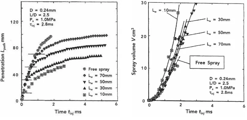
Figure 1-5 Penetration of wall impingement sprays 6
Figure 1-6 Volume of wall impingement sprays 6
Figure 1-7 Effect of cavity size on spray development 7
Figure 1-8 Effect of wall angle on a skeleton spray 9
Figure 1-9 Effect of wall distance on a skeleton spray 9
Figure 1-10 Spray impingement model 10
Figure 1-11 Classification of fuel film breakup form by Weber number 11
Figure 1-12 Various impingement regimes 13
Figure 1-13 Main parameters of impingement spray 14
Figure 1-14 Schematic diagram for observation of adhered fuel film 15
Figure 1-15 Comparison radius of adhered fuel with expanded spray 15
Figure 1-16 The results of Saito and Kawamura 16
Figure 1-17 Photographs of the impingement spray taken from side
and rear view (Lw = 30 mm, Pa = 1.5 MPa, tinj = 2.7 ms) 16
Figure 1-18 Photographs of the impingement spray and the
fuel film at Pa = 1.0 MPa 16
Figure 1-19 Spreading ratio Df/Ws at various wall distances
and ambient pressures 17
Figure 1-20 Adhering fuel ratios at various wall distances and
ambient pressures 18
Figure 1-21 Adhering fuel ratios versus various of
wall distances and ambient pressures 19
Figure 1-22 Adhering fuel ratios versus injection pressures 19
Figure 1-23 Calculated adhered fuel distribution 19
Figure 1-24 Comparison of film thickness 19
Figure 1-25 Effect of impingement distance from the injector
on overall transient SMD 23
Figure 1-26 Effect of injection pressure on mean droplet size 24
Figure 1-27 Photo density distribution of diesel spray 26
viii
Figure 1-29 Schematic diagram of the new combustion system
with an impingement cavity 28
Figure 1-30 Schematic diagram of GHN and SHN 29
Figure 2-1 Deposit formation mechanism in an engine 43
Figure 2-2 General method of impinging diesel spray investigation 45
Figure 2-3 Photograph of impinging diesel spray test bench 46
Figure 2-4 Schematic diagram of the normal wall
impingement apparatus 46
Figure 2-5 Diesel spray and normal set-up of impingement disk 47
Figure 2-6 Diesel spray and inclined set-up of impingement disk 47
Figure 2-7 Photograph of various size of disk diameter 50
Figure 2-8 Measurement procedure 51
Figure 2-9 Definitions of injection velocity, mean diameter
and Weber number of droplet 54
Figure 2-10 Time history of injection rate 54
Figure 2-11 Injection mass of fuel 55
Figure 2-12 Spray tip velocity 56
Figure 2-13 Calculated Sauter mean diameter 57
Figure 2-14 Effects of injection period and injection shot
number on adhered mass of fuel 57
Figure 2-15 Experimental setup with PIV consideration 59
Figure 2-16 3D and 2D construction of impinging diesel spray 60
Figure 2-17 Flow patterns of diesel spray to flat wall
impingement and bar impingement 61
Figure 3-1 Various evaluation indexes of adhered fuel 66
Figure 3-2 Effects of impingement distance and injection pressure on adhered mass ratio of 20 mm impingement disk 67
Figure 3-3 Effects of impingement distance and injection pressure on adhered mass ratio of 30 mm impingement disk 69
Figure 3-4 Effects of impingement distance and injection pressure on adhered mass ratio of 40 mm impingement disk 69
Figure 3-5 Relationship between adhered mass ratio and
impingement velocity 71
Figure 3-6 Effects of impingement disk area and injection pressure on adhered mass ratio of 30 mm impingement distance 71
ix
Figure 3-8 Pressure effect on adhered mass ratio 73 Figure 3-9 Shadowgraphic images of 30-mm impingement spray 76
Figure 3-10 Shadowgraphic images of 50-mm impingement spray 77
Figure 3-11 Shadowgraphic images of 70-mm impingement spray 78
Figure 3-12 Relation of adhered mass ratio and height of
post-impingement spray 80
Figure 4-1 Relationship between impingement disk area and
adhered fuel mass ratio 85
Figure 4-2 Models of adhering fuel on various sizes of disk 87
Figure 4-3 Effects of impingement distance and injection pressure on Dd.critical and Ws.imp 89
Figure 4-4 Relationship between injection pressure and critical
liquid film thickness 91
Figure 4-5 Adhered mass ratio for disks of Dd > Dd.critical 93
Figure 4-6 Modified adhered mass ratio with adhesion area factor for various impingement disk diameters at Lw = 30 mm 93
Figure 4-7 Modified adhered mass ratio with adhesion area factor
for various impingement disk diameters at Lw = 90 mm 94
Figure 4-8 Shadowgraphic images of impingement spray
(Lw = 30 mm and Pinj = 130 MPa) 95
Figure 4-9 Velocity components of impingement diesel spray 95
Figure 4-10 Relationship between inclination angle and adhered
mass ratio 96
Figure 4-11 Modified adhered mass ratio for various inclination angles 97
Figure 4-12 Model of impingement and non-impingement part of
diesel spray 99
Figure 4-13 Tomographic images of post-impingement spray for
various impingement angle and its velocity field 100
Figure 4-14 Tomographic of dolphin nose for various
impingement angles 101
Figure 4-15 Mean velocity distribution of the post-impingement
diesel spray 103
Figure 5-1 Various evaluation indexes of fuel spray 107
Figure 5-2 Effects of impingement distance and injection pressure
on Wed 108
Figure 5-3 Relationship between impingement disk area and
x
Figure 5-4 Weber number of impinging droplet and adhered mass ratio 112
Figure 5-5 Relationship between Wed and adhered mass ratio
modified by adhesion area factor 114
Figure 5-6 Relationship between inclination angle and adhered
mass ratio 115
Figure 5-7 Relationship between Wed and modified adhered
mass ratio for various inclination angles 116
Figure 5-8 Relationship between Wed.n and modified adhered mass ratio for various inclination angles
(Injection pressures were 40, 100, 130, and 170 MPa) 117
Figure 5-9 Relationship between Wed.n and modified adhered mass ratio for various inclination angles
(Injection pressures were 100, 130, and 170 MPa) 117
Figure 5-10 Combined modified adhered mass ratio for various impingement disk diameters, inclination angles
and injection pressures 120
Figure 6-1 Relationship between DSMD and Weinj 125
Figure 6-2 Effects of ambient pressure on Wed 126
Figure 6-3 Relationship between impingement disk diameter and
adhered fuel mass ratio (Pinj = 130 MPa) 128
Figure 6-4 Effect of ambient pressure on adhered mass ratio 130
Figure 6-5 Effects of ambient pressure and impingement distance
on adhered mass ratio 131
Figure 6-6 Shadowgraphic images of 30, 50, 70 and 90-mm impingement spray with effects of ambient pressure
(Pinj = 130 MPa) 134
Figure 6-7 Behavior of height of impingement spray
at Pinj = 130 MPa 136
Figure 6-8 Shadowgraphic images of 30 and 90-mm impingement
spray with effects of ambient pressure (Pinj = 40 MPa) 137
Figure 6-9 Behavior of height of impingement spray (Pinj = 40 MPa) 138
Figure 6-10 Relationship of height of impingement spray and
adhered mass ratio 140
Figure 6-11 Weber number of impinging droplet and adhered mass ratio 141
Figure 6-12 Relationship between Wed and modified adhered mass ratio
xi
Figure 6-13 General modified adhered mass ratio for various ambient pressure, injection pressure, inclination angles and
impingement disk diameters 144
List of tables
Table 2-1 Main experimental conditions 49
Table 2-2 Experimental conditions
(based on different investigation conditions) 51
Table 3-1 Spray velocity 75
Table 5-1 Droplet velocity and Weber number at impingement point 110
Table 6-1 Droplet velocity and Weber number at impingement point 127
List of abbreviations
CO2 Carbon dioxide DI Direct injection
EGR Exhaust gas circulation
HC Hydrocarbon
H2O Water
HSDI High spreed direct injection NA Natural aspirated
NOX Oxides of nitrogen
PDA Phase doppler anemometer PDPA Phase doppler particle analyzer PIV Particle image velocimetry PM Particulate matter
PCCI Premixed charge compression ignition HCCI Homogeneous charge compression ignition PDS Planar droplet sizing
xii
minj Mass of a single shot injection fuel [mg/injection]
madh adhered mass [mg]
madh.critical Critical adhered mass [mg]
N Number of injections [-]
tcritical Critical thickness of liquid film [mm]
tadh Thickness of adhered film [mm]
tasoi Time after start of injection [msec]
tais Time after impingement start [msec]
xiii
adh Adhered mass ratio [-]
adh Adhered mass ratio with ambient pressure effect [-]
d Inclination angle [deg.]
fuel Density of fuel [kgm-3]
a Ambient density [kgm-3]
σ Surface tension [kg/s2]
μl Fuel viscosity [g/mm-s]
μa Ambient viscosity [g/mm-s]
xiv
Abstract
1
Chapter 1
Impinging diesel spray and its research problems
1.1 Introduction
Over the last decade, study and research on diesel spray have progressed significantly. Many research works have been performed by automotive engineers to improve the performance of diesel engines and to reduce the exhaust emissions as well as fuel consumption.
In a high-speed DI diesel engine, behavior, structure and characteristics of diesel spray have been investigated by many researchers [1, 2, 3, 4, 5, 6, 7, 8, 9, 10, 11, 12, 13, 14]. From the viewpoint of spray combustion in the piston cavity, spray impingement on a cavity wall and fuel film adhering to its wall surface have a strong influence on combustion processes, engine performance and also characteristics of diesel exhaust harmful emissions. However, there are a few studies on impinging diesel spray with regard of adhering fuel on the cavity wall. Then it is necessary to understand the effect of fuel adhering when the spray impinges on the cavity wall.
In this chapter, various aspects of impinging diesel spray available in current literatures are reviewed in order to have a better understanding of the impinging diesel spray on the wall. Also, the adhering fuel, which is formed when the spray impinges to a wall, is discussed as an important factor in wall impingement spray. Furthermore, an understanding of the impinging diesel spray mechanisms is crucial for finding the best way on improving engine performance as well as reducing emissions which occurred in the combustion process. The information and knowledge obtained from literatures could give a clear view of the impinging diesel spray in this study.
1.2 General views of diesel spray
1.2.1 Diesel sprays in the combustion process
2
turbulences in the cylinder, and spray characteristics. The spray characteristics control the vaporizing characteristics and the ignition delay characteristics and finally give a great influence on the combustion process and also the exhaust emissions.
Figure 1-1 Block diagram of diesel combustion [15]
3
Figure 1-2 Diesel spray combustion in DI diesel engine [16]
For better understanding of the spray characteristics, Fig. 1-3 shows the characteristic parameters of a diesel spray and also well known as macroscopic parameter [17]. Those parameters shown in Fig. 1-3 are the important parameters in free spray and they are related to each others. The movement of the spray tip and break-up length gives clues to understand the disintegrating process of a fuel jet. Spray angle and droplet size are the result of the disintegrating process. A wide of spray angle usually meant the spray having a short breakup length and short core of spray, while narrow spray angle resulted to long breakup length. The adhesion of fuel on the wall normally occurred from the long breakup length condition. As shown in Fig. 1-2, a spray with long breakup length resulted in high HC and PM emissions. Diesel spray was a spray which droplet size distribution was in a range around few micrometers to 40 micrometers. The mean droplet size of spray or so called Sauter mean diameter (SMD), represent as the volume-surface mean diameter of spray. The SMD was one of the representative mean diameter and very popular in diesel spray study. It was very important in estimating the size of droplet for better understanding of the evaporation process. Turbulence also counted as one of the important parameters where it was usually activated mixing and evaporation in periphery region of the spray. Further, the intensities of the turbulence was more important in order to promote combustion process inside the spray.
4
Figure 1-3 Characteristics parameter of diesel spray [17]
Structure and shape of impinging spray had been described by Katsura et al.
[18] as shown in Fig. 1-4. They described the impinging spray was separated by two parts namely as unimpinged part and impinged part. An unimpinged part was similar as a free spray structure as shown in Fig. 1-3 but impinged part was somehow different. The impinged part was divided by several regions. In the wall main jet region, the spray velocity decreased after impingement and also high droplet density appeared along the impingement wall. Stagnate region that occurred at the edge of impinged part due to droplets in the periphery regions, were pushed upward and resulted to loss of momentum. Also, the wall jet vortex phenomena appeared at a peripheral region of the impinging diesel spray. In this region, the density of droplets was large and turbulent mixing occurred between spray and surrounding gas. In this region also, the spray height could be measured for further impingement spray analysis [18, 19, 20, 21, 22].
As described above, both of free spray and impingement spray are heterogeneous in their structures and shapes. In a practical diesel engine, since very short time is allowed for mixing and combustion process between injected fuel and air, the lack of homogeneity in the carburetted mixtures, and the heterogeneity and rapid variations in the temperature do not allow for the ideal combustion process. It would be worse when the adhering fuel deposited on the piston or cavity wall. Adhered fuel caused to the incomplete combustion of hydrocarbons results in the formation of a wide range of harmful gaseous components. Thus, more homogenous spray structure is required for complete combustion in the engine and also for developing advanced combustion system.
5
Figure 1-4 Structure and shape of impinging diesel spray [18]
1.2.2 Wall impingement and its spray-wall interaction
(a) Wall impingement
Recently the combustion chamber in a diesel engine tends to be small in order to reduce fuel consumption, and injection pressure tends to increase as compared with a conventional diesel engine. Wall impingement of the spray might occur due to downsizing of the engine and high pressure of fuel injection, and unevaporated diesel fuel was adhered on the wall of cavity. The impingement spray causes the emission of hydrocarbon (HC) and soot from the diesel engine. Therefore it is important to understand the spray-wall interaction and adhesion characteristics of impingement diesel spray.
6
penetration length of sprays under non-evaporating condition and injection pressure from 40 MPa to 100 MPa. They found that almost similar trend of spray path penetration as Fig. 1-5.
Volume of wall impingement sprays is shown in Fig. 1-6 [23]. The spray volumes of Lw = 30, 50 and 70 mm show almost the same values even though there were small differences between these values. Results also show that the spray volume for all impingement cases are higher than free spray case. They concluded that, the volume of spray could be increased more than free spray case if the spray broke up before impinging on the wall. It was also reported by Tsunemoto et al. [25] that the spray volume and area which contacting with air were increased by spray impingement. However, in case of projected area, spray did not changed in volume and area that contacting with air. Tanabe et al. [26]
studied the behavior of impinging spray onto projection of the flat wall. They reported that penetration length and the spray height was increased by increased of nozzle opening pressure.
Figure 1-5 Penetration of wall impingement sprays [23]
Figure 1-6 Volume of wall impingement sprays [23]
(b) Impingement spray behavior
7
that the combustion chamber with round lip and optimum wall distance gives better fuel distribution.
Figure 1-7 Effect of cavity size on spray development [27]
As shown in Fig. 1-7, they also suggested that, shorter wall distance (deep cavity) could cause to interference between the injected sprays, while too long wall distance (shallow cavity) could create un-used space between two neighboring sprays. Thus, the optimum of wall distance is important in order to get a minimum adherence of spray on cavity wall.
Katsura et al. [18] pointed out that by shortening the impingement distance, the droplet density becomes higher and changed accordingly along the wall. Zurlo et al. [28] was measured the droplet size distribution of post impingement spray by using polarization ratio measurement technique. They reported that droplet size was smaller when closed to the wall compared to the droplet far from the wall. Another researcher [29] investigated the effect of wall distance on the SMD of the post impingement spray. They found that as the impingement distance decreasing, the SMD of the post impingement spray became smaller. By using Exciplex Fluorescence Method, Senda et al. [30, 31] proposed 2-D images concerning the concentration distribution of vapor and liquid phases which acquired simultaneously. The observed vapor phase growth upward clearly from the wall to the periphery region while the liquid phase expanded mainly along the wall in the radial direction. Then, it was found that small droplets near the tip of the liquid phase evaporated rapidly due to the hot ambient surroundings, and then the evaporated fuel mixed and diffused with the surroundings.
8
investigation from Arai et al. [33] and Nishida et al. [34] on the diesel spray with split investigation. They reported that, mass measured from the second stage of injection was large compared to the mass that was measured in interval between the first and second stages of injection.
Since the diesel spray was not necessarily to impinge vertically to the wall of the engine cylinder, effect of the inclination angle of impingement became important for the impingement of a diesel spray. Arai [35] reviewed many kinds of diesel spray impingement phenomena including combustion of impingement diesel spray to an inclined wall. As for inclined diesel spray impingement, Fujimoto et al. [36] investigated the effect of impingement distance, injection pressure and ambient pressure on characteristics of inclined impinging diesel spray. They found that higher downward flow of spray became appearing when increasing the inclination angle wall.
Ebara et al. [37, 38] estimated the spray penetration under the effect of inclined wall impingement. According to them, as the inclination angle increased the spray path penetration became shorter compared to the free spray. They concluded that, mixing process between spray and surrounding was promoted in the cases for larger inclination angles (like normal impingement). However, they were not discussed the effect of inclined wall on the flow of impinged spray along the wall.
Further they enhanced their research on the inclined impingement spray by used of image analysis visualized by YAG laser sheet [39, 40]. Skeleton images had been introduced by them in order to discuss the effect of wall distance and inclination angles on high density of the spray zone. Figure 1-8 are the example of the effect of wall angle on a skeleton spray. Effect of wall distance on the skeleton images was clarified in Fig. 1-9. It was observed that liquid column impinged on the wall and high density of spray layer occurred for short impingement distances such as Lw = 10 and 20 mm. They suggested that the high density zone occurred due to roll-up motion of the spray layer on the wall surface. Besides, at Lw = 30 and 50 mm, the high density zone distributed along the some height from the wall. They considered that spray completed the breakup process during impinging on the wall.
9
Figure 1-8 Effect of wall angle on a skeleton spray [40]
Figure 1-9 Effect of wall distance on a skeleton spray [40]
![Figure 1-1 Block diagram of diesel combustion [15]](https://thumb-ap.123doks.com/thumbv2/123dok/520141.59609/17.595.162.444.172.552/figure-block-diagram-diesel-combustion.webp)
![Figure 1-2 Diesel spray combustion in DI diesel engine [16]](https://thumb-ap.123doks.com/thumbv2/123dok/520141.59609/18.595.128.486.89.319/figure-diesel-spray-combustion-in-di-diesel-engine.webp)
![Figure 1-3 Characteristics parameter of diesel spray [17]](https://thumb-ap.123doks.com/thumbv2/123dok/520141.59609/19.595.225.392.101.258/figure-characteristics-parameter-diesel-spray.webp)
![Figure 1-4 Structure and shape of impinging diesel spray [18]](https://thumb-ap.123doks.com/thumbv2/123dok/520141.59609/20.595.161.456.88.332/figure-structure-shape-impinging-diesel-spray.webp)
![Figure 1-7 Effect of cavity size on spray development [27]](https://thumb-ap.123doks.com/thumbv2/123dok/520141.59609/22.595.204.412.128.298/figure-effect-cavity-size-spray-development.webp)
![Figure 1-8 Effect of wall angle on a skeleton spray [40]](https://thumb-ap.123doks.com/thumbv2/123dok/520141.59609/24.595.174.442.304.605/figure-effect-wall-angle-skeleton-spray.webp)
