OPTIMUM HEAT EXCHANGER NETWORK ONLINE CLEANING SCHEDULE FOR CRUDE DISTILLATION UNIT
NUR IZYAN BINTI ZULKAFLI
RESEARCH VOTE NO : PJP/2012/FKM(10C)/S01014
Fakulti Kejuruteraan Mekanikal Universiti Teknikal Malaysia Melaka
ACKNOWLEDGEMENT
First and foremost, I thank to Allah SWT, the Almighty God for His guidance and blessings that give me strength and wisdom to complete this project.
I would like to express my sincere gratitude to my co-researchers Noryani binti Muhammad and Dayanasari binti Abdul Hadi for their dedication and support throughout this project.
The greatest gratitude and thanks to Sustainable Maintenance Engineering Research Group under the Centre of Advanced Research on Energy, Universiti Teknikal Malaysia Melaka for providing research grant and helpful assistance throughout this project.
Finally but certainly not the least, much of gratitude goes to all my family members for their endless encouragement and support throughout completing this project.
OPTIMUM HEAT EXCHANGER NETWORK CLEANING
SCHEDULE FOR CRUDE PREHEAT TRAIN
(Keywords: fouling, cleaning, schedule, retrofit, heat exchanger)
There is greater awareness today on the depleting fossil energy resources and the growing problem of atmospheric pollution. Engineers are developing practical techniques to ensure energy processes are designed and operated efficiently. Inefficient heat exchangers lead to higher fuel demand and higher carbon emission. This paper presents mixed-integer nonlinear programming (MINLP) model for simultaneous cleaning and retrofit of crude preheat train (CPT) in oil refinery plant. The formulation of the model is generated and coded in General Algebraic Modeling System (GAMS). The model minimizes the cost of energy and the cost of cleaning. The model takes into account the changes in fouling rates throughout time. There are two cases for this study. The cases are online cleaning (Case 1) and simultaneous online cleaning and retrofit (Case 2). The largest energy saving are found in Case 2. The installation of high efficiency heat exchangers improves furnace inlet temperature (FIT) from 215oC to 227oC. Furthermore, Case 2 results in the highest percentage of cost saving by about 59%. The payback period for investment in high efficiency heat exchangers is 5 months. Thus, Case 2 is the most cost effective option for reductions of energy consumption in Crude Distillation Unit (CDU).
Key Researchers:
Nur Izyan binti Zulkafli Noryani binti Muhammad Dayanasari binti Abdul Hadi
Email: [email protected]
Tel. Number: 06-2346882
Project Number: PJP/2012/FKM(10C)/S01014
TABLE OF CONTENT
1.1 Crude Distillation Unit………. 1
1.2 Fouling of Heat Exchangers………. 1
1.3 Heat Exchanger Cleaning………. 3
1.4 Selection of Heat Exchangers to Minimize Fouling………. 5
1.5 Furnace Operation……… 8
2.1 Establishment of Base Case Data………. 12
2.2 Model Formulation………... 14
2.3 Feasibility and Economic Analysis……….. 15
2.4 Summary of Research Methodology……… 16
3. RESULTS AND DISCUSSION………... 18
3.1 Development of Model Formulation……… 18
3.2 Case 1: CPT Online Cleaning Schedule………... 21
3.3 Case 2: Simultaneous CPT Online Cleaning and Retrofitting Schedule………. 22 3.4 Feasibility Analysis……….. 24
3.5 Economic Analysis………... 26
4. SUMMARY AND CONCLUSION……….. 29
4.1 Conclusion……… 29
4.2 Future Works……… 30
REFERENCES……….. 31
APPENDICES………... 33
Appendix A: Model Formulation in GAMS Software………... 33
LIST OF TABLES
Pages Table 1.1 Features of some typical types of heat exchanger 5
Table 2.1 Heat exchangers before desalter unit 14
Table 2.2 Heat exchangers after desalter unit 14
Table 3.1 Data for heat exchanger network 21
Table 3.2 Comparison of energy saving for all cases 25
Table 3.3 cleaning schedule for Case 1 25
Table 3.4 cleaning schedule for Case 2 26
Table 3.5 Base Case cost calculation 26
Table 3.6 Total cost for Case 1 and Case 2 27
Table 3.7 Purchase cost for compabloc heat exchangers 28
LIST OF FIGURES
Pages Figure 1.1 Picture of fouled (a) and clean (b) shell and tube heat exchanger 2
Figure 1.2 Idealised deposition curves 3
Figure 1.3 Sectional view of Compabloc 7
Figure 1.4 Schematic diagram of crude furnace operation 9
Figure 2.1 CDU crude preheat train flow scheme 13
Figure 2.2 Flowchart of the overall research methodology 17
Figure 3.1 Fouling resistance behaviour for CPT 20
Figure 3.2 FIT profiles 24
NOMENCLATURES
A Heat transfer are of heat exchanger (m2) Ccl heat exchanger cleaning cost (RM/unit) Cfl furnace’s fuel cost (RM/GJ)
Cpl production lost cost due to plant shutdown (RM/unit) Cph purchase cost for heat exchanger ($)
Cc specific heat for cold stream (kJ/kmol.oC) Ch specific heat for hot stream (kJ/kmol.oC) Fc cold stream flow rate (kg/h)
Fh hot stream flow rate (kg/h) FG fuel gas flow rate (m3/h) FIT furnace inlet temperature (oC) m mass flow rate (kg/h)
Rf fouling resistance (m2.oC/kW) dRf fouling rates (m2.oC/kW)
dRfhex fouling rates for high efficiency heat exchanger (m2.oC/kW) Th1 inlet hot stream temperature (oC)
Th2 outlet hot stream temperature (oC) Tc1 inlet cold stream temperature (oC) Tc2 outlet cold stream temperature (oC) Q heat duty (kW)
U overall heat transfer coefficient (kW.m2/oC) Uc overall clean heat transfer coefficient (kW.m2/oC) Uf Overall fouled heat transfer coefficient (kW.m2/oC) y binary variable for CPT cleaning
∆FG extra fuel gas flow rate (m3/h) ∆H enthalpy (kW)
∆Hc heat of combustion (kW)
Subscript
i heat exchanger
t period
Greek letter
α conversion factor (GJ.h/month.m3) Ƞ furnace efficiency
CHAPTER 1
INTRODUCTION
1.1 Crude Distillation Unit
The crude distillation unit (CDU) is the first step in a refinery complex to separate crude oil into different fractions depending on the difference of boiling temperatures of the various constituents. In a typical CDU, the crude oil feed stream is preheated in a crude preheat train (CPT) in two sections. The first section runs from storage to a desalter unit. While, the second section runs from desalter to the furnace. The main function of the desalter unit is to remove salts, water and sediment present in the crude oil feed stream. CPT utilizes the high temperatures of the distillation column product streams. The crude outlet temperature of the CPT could reach up to 280oC. Then, the crude oil is further heated up in the furnace. Typical furnace outlet temperature values are 350oC to 380oC. The heated crude oil enters crude distillation column. It is a long column that consists of many trays. These trays have bubbles or holes to allow vapour to pass through them. Crude fractions settle in the rectifying section trays and are drawn off at four liquid side cuts depending on their average boiling point. The side cuts are naphtha, kerosene, diesel and fuel oil. The liquid that is drawn in the bottom tray of distillation column is atmospheric residue. (Al Muslim, et al., 2003)
1.2Fouling of Heat Exchangers
The accumulation of deposits on the surfaces of heat exchangers is known as fouling. In CPT, the deposits may be crystalline, particulate matter, chemical reaction and corrosive material. The formations of these deposits depend on the fluid passing through the heat exchanger.
be caused by evaporation of solvent, cooling below solubility limit of solution, heating above solubility limit of solution and mixing of streams with different composition. Particulate fouling is the deposition of small suspended particles such as clay, silt or iron oxide on heat transfer surfaces. Fouling may also be caused by chemical reactions, where deposits are formed at the heat transfer surface. Meanwhile, the corrosion of the heat transfer surface will increase the surface roughness. The increased surface roughness of heat transfer area may promote corrosion fouling to occur (Steinhagen, 2000).
Figure 1.1 shows a shell and tube heat exchanger that is fouled with particulate matter. Figure (a) on the left is a badly fouled heat exchanger tubes while figure (b) on the right shows the tube condition after cleaning.
Figure 1.1 Picture of fouled (a) and clean (b) shell and tube heat exchanger
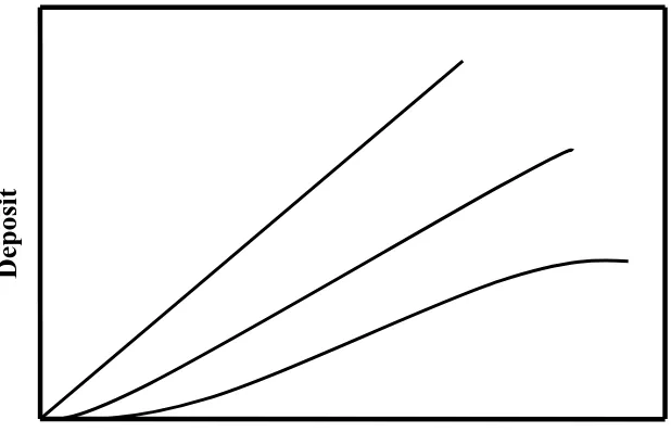
The progressing of fouling with time is ideally illustrated in Figure 1.2. Line A represents a linear relationship of deposit thickness with time. The linear relationship indicates that the rate of development of the fouling layer is constant along the period of time, t. Line B represents a falling rate of deposition once initiation has occurred. If the process of deposition are allowed to progress sufficiently an asymptotic curve would be produced as presented by line C (Bott, 1995).
The presence of deposits causes resistance to heat transfer and reduces the heat transfer efficiency of heat exchangers. The reduction of heat transfer efficiency in heat exchangers over time increases fuel consumption. The additional fuels are needed to overcome the shortfall in energy recovered due to fouling problem. The effects of fouling in heat exchangers not only increase the operational cost but also increase carbon dioxide (CO2) that is emitted during fuel combustion. The increment of CO2 brings adverse impact to the environment due to the effect of greenhouse gases emission that causes global warming on earth (Bott, 1995).
Figure 1.2 Idealised deposition curves
1.3 Heat Exchanger Cleaning
In order to maintain or restore heat transfer efficiency, it is necessary to clean the heat exchangers. The methods of cleaning are classified into two groups, namely online and offline cleaning. Online cleaning is performed during plant operation by isolating the heat exchangers through bypasses. Online cleaning can also be implemented for heat exchangers in parallel position where one heat exchanger is in operation mode while the other one is on standby mode. When the performance of heat exchanger in operation mode is reduced due to fouling, the online cleaning can be performed for fouled heat exchanger by putting the standby heat exchanger into operation mode.
Time, t
Dep
osit
A
The fouled heat exchanger has an opportunity to be cleaned. At the same time, online cleaning allows for the production to be maintained. Meanwhile, offline cleaning is performed when the plant is shutdown during plan or unplanned shutdown (Bott, 1995).
The choice of cleaning techniques depends on the accessibility of the fouled surfaces and the fouling severity in the heat exchangers. The common mechanical cleaning technique in refinery is steam-blasting and hydro-blasting. If deposits are very tenacious, sand can be added to the pressurized water to increase the cleaning efficiency. On the other hand, using air or hydropressure, rubber plugs or metal scrapers can be shot through the tubes. Metal scrapers is shot through the tubes at water pressure of 35 bars and a scraper velocity of 3-6 m/s results in the removal of deposits. In general, water pressure systems are safer than air pressure system due to the compressibility and subsequent rapid expansion of gases (Bott, 1995).
Chemical cleaning may be required if the deposits are difficult to remove by mechanical cleaning. The selection of chemical and the cleaning procedure depend on the type of deposit and the configuration of the heat exchanger on economic and environmental concern. Most chemical cleaning consists of five distinctive stages. The five stages are alkaline cleaning, alkaline rinses, acid cleaning, acid rinses and passivation. The aim of alkaline cleaning is to remove the organic surface of the deposit in order to make the inorganic surface hydrophilic. Once the surface is hydrophilic, the deposit is softened and dissolved by application of the suitable acid blend. This blend usually contains inhibitor to prevent corrosion of the base metal by the acid. Before and after each chemical step, high flow water flushes are required to soften the deposit. The last stage is passivation where the protective oxide film is formed on the base metal to avoid corrosion (Steinhagen, 2000).
1.4 Selection of Heat Exchangers to Minimize Fouling
The major consideration for the selection of heat exchangers is the suitable techniques for cleaning heat exchangers. The method of cleaning should be a feature of the preliminary concept in designing the heat exchangers.
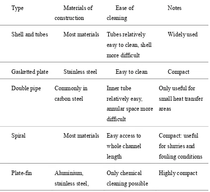
Table 1.1 lists some of the features of typical type of heat exchangers. It may be used as a preliminary guide in heat exchanger selection. For example, the shell and tubes heat exchanger is designed where the fluid that is likely to create higher fouling should be made to flow through the tubes sides of heat exchangers because tubes side is relatively easy to clean than the shell side. The fluid with lower fouling tendency should flow through the shell side of heat exchanger (Bott, 1995). The plate and frame heat exchanger may be attractive as it can be easily disassembled for cleaning and sterilising. The spiral heat exchanger performs well for fluids with a high concentration of suspended solids because low velocity region in this heat exchanger. Meanwhile, highly compact heat exchanger is normally avoided for severe fouling conditions as it is difficult to clean.
Table 1.1 Features of some typical types of heat exchanger
Type Materials of
construction
Ease of cleaning
Notes
Shell and tubes Most materials Tubes relatively easy to clean, shell more difficult
Widely used
Gasketted plate Stainless steel Easy to clean Compact
Double pipe Commonly in
titanium
The most common heat exchanger applied in oil refinery is the shell and tube heat exchanger. The shell and tube heat exchanger is a reliable and well proven technology. It tolerates high design temperatures and pressures and can undertake almost any range of duty. However, the shell and tube requires a large heat transfer area as a result of a rather low overall heat transfer coefficient. In addition, the construction often involves the use of materials that are rather thick compared with plate type heat exchanger. The result is a large and heavy construction which entails high purchase and installation cost (Arvidsson, 2003).
One of the encouraging aspects for heat exchangers is the advances in development of compact heat exchanger. The use of compact heat exchanger in industry has its advantages in reducing energy consumption of operation and minimizing capital investment (Hesselgreaves, 2001).
One compact heat exchanger available in the market today is Alfa Laval’s Compabloc welded plate heat exchanger. Figure 1.3 demonstrates the sectional view of Compabloc. The two media in the Compabloc heat exchanger flow in alternately welded channels between the corrugated plates. These corrugated plates promote high turbulence which provides high heat transfer efficiency and help minimize fouling. The corrugated plates are welded alternately to form channels. By simply unbolting the side panels, it is possible to gain access for inspection, service or cleaning by hydro blasting with a high pressure water jet. The media flows in a cross-flow arrangement within each pass as shown in Figure 1.3. Each pass is separated from the adjacent passes by a pressed baffle which forces the fluid to turn between the plate pack and the panel (Gunnarsson et al., 2008).
The high turbulence created by the corrugated pattern in the Compabloc results in very efficient heat transfer and minimises fouling problem. The heat transfer coefficient in a Compabloc is normally 2-4 times higher than in shell and tube heat exchanger. The compactness of the Compabloc means that the hold up volume is very low. The low hold up volume provides quick startup, easy control and fast response time. The high heat transfer efficiency in the Compabloc makes a temperature approach closer than shell and tube heat exchanger. (Arvidsson, 2003).
Figure 1.3 Sectional view of Compabloc
1.5 Furnace Operation
Oil refining and petrochemical plants involve extensive heating of hydrocarbon and other fluids. The fluid is heated by direct heating to achieve the required temperature. Direct heating is the process where the fluid under pressure that is contained in tubes is heated from the outside by direct exposure to flames. The oil refining and
petrochemical furnaces commonly have two forms of furnaces. These are the cylindrical furnaces with one central burner or a ring of burners in the base and cabin furnaces with many burners in a row along the floor. The primary aim of a furnace operation is to attain a high processing temperature. In the furnace, heat is liberated by burning fuel with air or oxygen and some of this heat is transferred to the fluid. This process is known as combustion process where fuel and oxygen are burnt together at sufficiently high temperature to produce heat and combustion products. The combustion is completed when only carbon dioxide is produced. Complete combustion can be achieved by providing excess air. Incomplete combustion of fuel is associated with the formation of carbon monoxide. The products of combustion which leave the furnace through a furnace stack are known as flue gas. (Mullinger et al., 2008).
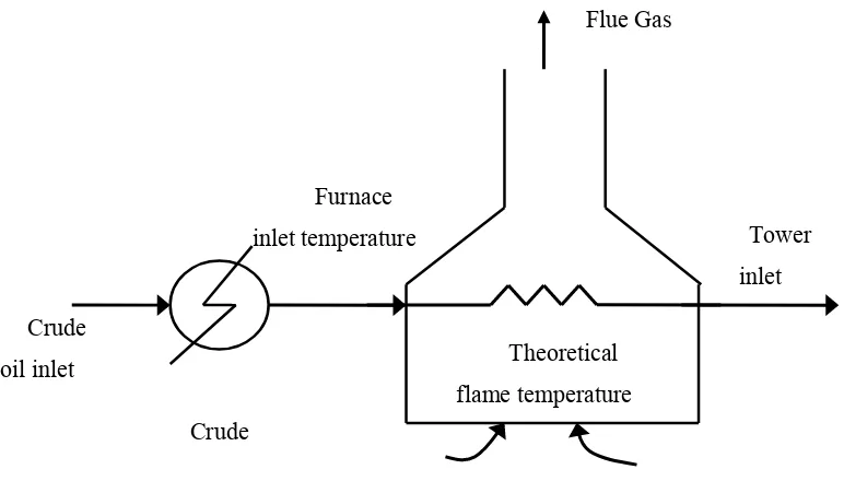
Figure 1.4 illustrates a schematic diagram of the crude furnace operation. The crude is preheated by crude preheat train before entering the furnace at furnace inlet temperature (FIT). The heat source is provided by the burning of fuel with air at theoretical flame temperature (TFT). TFT is a calculated temperature of flame. TFT is possible when the combustion is completely adiabatic. The heat from the burning of fuel with air is transferred to the crude oil. The heated crude oil enters the crude distillation column at tower inlet temperature (TIT). The remaining heat in the furnace leaves through the furnace stack at stack temperature (T stack).
The main contribution of high furnace efficiency is effective heat transfer and the heat transfer from flames is largely by radiation. The radiant heat transfer is proportional to the flame emissivity. The fuel with high flame emissivity is preferred for high temperature process because radiation normally contributes the greater proportion of heat transfer under this condition. When fuel with low flame emissivity is used, furnace must be designed to increase the contribution of convective heat transfer (Mullinger et al., 2008). Fuels with high carbon/hydrogen (C/H) ratios, for example oils and solid fuels, are more likely to burn with luminous flames due to high flame emissivity. Fuels with low C/H ratios, mostly gaseous fuels, tend to burn with clear flames due to low flame emissivity. The heat transfer from a luminous flame is usually greater than clear flame at the same temperature (Trinks, 2003).
Figure 1.4 Schematic diagram of crude furnace operation
1.6 Problem Statement
The accumulation of unwanted deposits on the surface of heat exchangers, or fouling, reduces the overall heat transfer efficiency in the CPT of a CDU. The reduction of heat transfer efficiency in CPT causes significant increment of fossil fuel consumption in the furnace. The higher consumption of fuel may be also caused by reduction of furnace efficiency due to greater heat loss to the surrounding. The high furnace stack temperature may contribute to greater furnace heat loss. The additional consumption of fossil fuel is needed to overcome the shortfall of energy recovered and this will affect the conservation of limited energy resources. The higher consumption of fossil fuel also causes environmental problem due to higher emission of carbon dioxide from combustion of fossil fuel to the atmosphere. Furthermore, the operational cost of the plant increases not only contributes to high consumption of fuel but also product yield and throughput reduction. In order to overcome this problem, heat exchangers are cleaned between shutdowns or during operations to
Theoretical flame temperature Furnace
inlet temperature Tower
inlet Flue Gas
Crude Crude
oil inlet
restore its efficiencies. However, the most crucial factor for heat exchanger network cleaning schedule is to determine which heat exchanger need to be cleaned and when during operation. The loss of production that is caused by plant shutdown for cleaning is often more significant than the cost of heat exchangers cleaning. The time of which heat exchanger has to be cleaned is a scheduling problem where considerations between the cost of cleaning, the cost of fuel consumption and the cost of production lost need to be compromised.
1.7 Objectives
The main objective of this research is to optimize the model for simultaneous scheduling and retrofit of CPT with reasonable payback period and contribute to the highest energy saving as well as cost saving.
1.8 Methodology
The relevant process data are extracted from a refinery to establish performance benchmark of the system. The set of equations are presented to simulate online cleaning schedule for CPT. The model minimizes the total operating cost by finding the balance point between fouling and the cleaning cost. The first model is optimum online cleaning of heat exchangers. The current study extends the first model to develop combined online cleaning with retrofit of high efficiency heat exchangers. The models are simulated to obtain optimal heat exchanger cleaning schedules, furnace inlet temperature (FIT) and extra fuel gas profiles. The models are proposed to minimize energy consumption and carbon dioxide emission as well as operational cost of the plant
1.9 Scope of Study
This study is conducted on a typical refinery in Malaysia. The scope of this study is on the CPT and furnace in CDU. The relevant process data are extracted from the
refinery to produce a set of base case data. All the models are coded in the commercial optimization software, GAMS version 23.9 and solved by BONMIN solver. Mixed Integer Non Linear Programming (MINLP) cleaning schedule optimizer models are applied for all the cases. The model determines which heat exchanger needs to be cleaned in which period of time with some resource availability and constraints so that the total operating cost is minimized.
CHAPTER 2
METHODOLOGY
2.1 Establishment of Base Case Data
The relevant process data is obtained from operational, simulation and design data. The selected data has been agreed and validated by a local oil refinery’s engineers after careful consideration. Temperatures of hot and cold streams of CPT are obtained from manual temperature monitoring spreadsheet prepared by refinery production department. The process flow rate was taken from process information (PI) historical data over 12 months while the material properties for crude oil and its products are obtained from the simulation data prepared by the plant engineers.
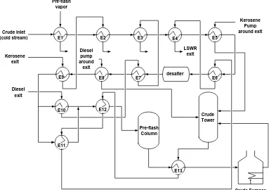
Figure 2.1 shows a simplified process flow scheme of CDU crude preheat train. From the process flow scheme, the hot streams are pre-flash vapour, kerosene, diesel, LSWR, kerosene pump around, diesel pump around and pre-flash bottom. The hot stream for heat exchanger E2 and E9 is kerosene exit. The hot stream for heat exchanger E3, E7 and E10 is diesel exit. The hot stream for heat exchanger E4, E11 and E12 is LSWR exit.
The crude oil is heated up to 112oC before entering the desalter. Table 2.1 lists heat exchangers before desalter unit with hot streams for heat recovery. The hot streams are the hot product streams coming out from the CDU. After desalter, the crude oil stream is further heated up using heat recovered from the process streams. The list of heat exchangers with hot streams after desalter unit is shown in Table 2.2. At this end, the crude oil starts to vaporize at 203oC. Then, the crude oil enters a pre-flash column to remove light naphtha, mixed naphtha and light hydrocarbon gases from the crude oil. The pre-flash column is equipped with 18 single passes fractionation trays located above the crude inlet. The vapour is risen up to pre-flash overhead distillate and the liquid flows downward to the bottom. The preflash column bottom is further heated by heat exchanger E13 before entering furnace at design temperature of 215oC.
E1 E2 E3 E4 E5
Figure 2.1 CDU crude preheat train flow scheme
Additional process heating is provided by crude furnace. The crude oil enters four passes of furnace, which is heated by the fuel gas burners. The heated crude oil exits the furnace at approximately 367oC before entering the CDU column flash zone. The CDU column is equipped with 29 valves type trays above the flash zone and 4 valve type trays below the flash zone. The vapour from the flash zone at the top section ascends the trays where they are fractionated into diesel, kerosene, heavy naphtha and overhead distillate. Meanwhile, the bottom section of the column is low sulphur waxy residual (LSWR). There are three refluxes which consist of overhead reflux naphtha, kerosene pump-around and diesel pump around.
Table 2.1 Heat exchangers before desalter unit
Heat exchangers Hot streams
E1 Pre-flash overhead exit
E2 Kerosene exit
E3 Diesel exit
E4 LSWR exit
E5 Kerosene Pump Around exit
E6 LSWR exit
Table 2.2 Heat exchangers after desalter unit
Heat exchangers Hot streams
E7 Diesel exit
E8 Diesel pump around exit
E9 Kerosene exit
E10 Diesel exit
E11 LSWR exit
E12 LSWR exit
E13 Pre-flash bottom exit
2.2 Model Formulation
The method to enhance heat recovery in the CPT is by improving furnace inlet temperature (FIT). Three cases are proposed to improve FIT, namely heat exchangers online cleaning (Case 1) and heat exchangers online cleaning with retrofit of high efficiency heat exchangers (Case 2).
The cleaning schedule formulation for Case 1 and Case 2 is incorporated by the following simplifications:
(i) Constant mass flow rates for all hot and cold streams (ii) Constant linear fouling rates obtained from historical data (iii) Pressure drop considerations were not included
(iv) Only heat exchangers in parallel position were allowed to perform online cleaning
All the models are coded in the commercial optimization software, GAMS version 23.9. Mixed Integer Non Linear Programming (MINLP) cleaning schedule optimizer models are applied for all the cases. The historical data for parameters such as fuel gas flow rate, furnace inlet temperature, hot streams and cold streams of heat exchanger network are collected. The historical data is needed to obtain correlation and profiles of the respective parameters.
2.3 Feasibility and Economic Analysis
The feasibility and economic analysis are conducted to investigate the performance of crude preheat train during online cleaning for Case 1 and Case 2. Feasibility analysis is conducted to investigate whether all the cases are viable and possible to implement in the plant. The criterions to decide the feasibility of the cases are comparison of energy and comparison of FIT profiles with current practice performance. The heat exchangers cleaning schedules for all the cases are presented in feasibility analysis section.
Meanwhile, the economic analysis is conducted to determine the operational cost for all the options. The operational cost for all the options are compared with operational cost for current practice to obtain percentage of cost saving. The operational cost is calculated with and without carbon credit revenue for all the options.
For Case 3, the purchase cost for high efficiency heat exchangers are calculated to obtain payback period. Seider et al. (2003) lists the purchase cost equation for chemical processing equipments. The purchase cost for plate and frame heat exchanger are as in equation (2.1) below. Cph is the purchase cost ($), A is the heat transfer area (ft2) with the range of 150-15000 ft2. The material is stainless steel. The operating pressures are limited to 300 psig.
42 exchanger with design pressure up to 450 psig (Gunnarsson et al., 2006).