DESIGN AND DEVELOPMENT OF REMOTELY OPERATED VEHICLE (ROV) FOR SHALLOW WATER
MUHAMMAD SAFIE BIN ROSLI
Thesis is submitted in fulfillment of the requirements for the awards of the degree of Bachelor of Mechatronic Engineering
Faculty of Electrical Engineering
UNIVERSITI TEKNIKAL MALAYSIA MELAKA (UTeM)
ii
STUDENT'S DECLARATION
I hereby declare that this thesis entitled "Design and Development of Remotely Operated Vehicle (ROV) for Shallow Water" is the result of my own research except as cited in the references. This is project is adequate in terms of scope and quality for the award of the degree of Bachelor of Mechatronic Engineering.
Signature :
Name : MUHAMMAD SAFIE BIN ROSLI
ID Number : B010910170
iii
SUPERVISOR'S DECLARATION
I hereby declare that I have checked this project and in my opinion, this project is adequate in terms of scope and quality for the awards of the Degree of Bachelor of Mechatronic Engineering.
Signature :
Name : PN. FADILAH BINTI ABDUL AZIS Position : Lecturer
iv
Specially dedicated to: My father, Rosli Bin Abdul Wahid
My mother, Samsiah Binti Ismail My sibling, Muhammad Suhaimi Bin Rosli
v
ACKNOWLEDGEMENT
First and foremost, I would like to express my sincere and gratitude to my supervisor Pn. Fadilah Binti Abdul Azis for guidance throughout the progress of this project, for her germinal ideas, invaluable guidance, continuous encouragement and constant support. This thesis would not have been possible without her guidance. I appreciate her consistent support from the first day I applied to graduate program to these concluding moments. I also sincerely thanks for the time spent proofreading and correcting my naive mistakes.
Moreover, my sincere thanks go to all members of the staff of the Mechatronic Engineering Department UTeM, who helped me and made my life studying in UTeM pleasant and unforgettable. Many special thanks go to my classmates and dear housemate for their excellent understanding, co-operation, inspiration and supports during this study.
I acknowledge my sincere and my great appreciation goes to all my family members who have been so patient and support me all these years. Without their encouragement and love, I would not be able to undergo the pressure due to this project. During the process of constructing design of prototype ROV, there are many difficulties that I faced but, with the guidance and supported from underwater team members, Syed Razlan Shah, Muhammad Fauzi and Goh Joen Sam, as well as all BEKM mates finally I was able to finished my first report for final year 1 smoothly.
vi
ABSTRACT
vii
ABSTRAK
viii
TABLE OF CONTENT
CHAPTER TITLE PAGE
TABLE OF CONTENT viii
LIST OF TABLES xi
LIST OF FIGURES xii
LIST OF ABBREVIATIONS xiv
LIST OF APPENDICES xv
1 INTRODUCTION 1
1.2 Project Background 1
1.3 Problem Statement 3
1.4 Objectives of the project 4
1.5 Scope of the project 4
2 LITERATURE REVIEW 5
2.1 Literature Survey 5
2.2 Material (Frame Body) 7
2.3 Buoyancy and Stability 10
2.4 Thruster 12
2.4.1 Propeller 13
2.4.2 Position of Thruster 14
2.5 Tether 15
2.6 Related Work 16
2.6.1 Design Comparison Table 21
2.6.2 K-Chart on designing the ROV 23 2.6.3 Pair wise Comparison & Weighted
Objectively Method 24
3 METHODOLOGY 27
3.1 PSM Flow Chart 28
3.2 Data Collection 29
ix
3.4 Electronic Construction 30
3.4.1 Electronic Wiring 31
3.4.2 PSC28A (Controller Circuit) 32
3.4.3 Relay Circuit Controller 32
3.4.4 Etching Circuit 33
3.4.5 Power Supply 34
3.4.6 Safety Features 34
3.5 Mechanical Construction 35
3.5.1 ROV Specification 35
3.5.2 Design ROV using Solid Work 37
3.5.2.1 Sketching 37
3.5.2.2 Design (Solid Work) 37
3.5.3 Ballast Tank 38
3.6 Centre of gravity 39
3.7 Weight Estimation 40
3.8 Experiment 50
3.8.1 Waterproof Testing 50
3.8.2 Buoyancy Testing 52
3.8.3 Operation Underwater Testing 54 3.8.3.1 Moving Forward and Reverse 54 3.8.3.2 Turn Right and Left 56 3.8.3.3 Raise and Submerge using Ballast Tank 58
3.10 Prepare Technical Report 59
3.11 Summary 59
4 RESULT AND ANALYSIS 60
4.1 Mechanical Construction Design 60
4.1.1 Design SMART ROV 60
x
4.2.1 Thruster 61
4.3 Experiment Results 62
4.3.1 Waterproof Body Structure 62
4.3.2 Buoyancy of ROV 63
4.3.3 Underwater Operation 64
4.3.3.1 Moving Forward and Reverse 64 4.3.3.2 Turn Right and Left 71 4.3.3.3 Raise and submerge using Thruster 73
5 CONCLUSION AND RECOMMENDATIONS 78
5.1 Conclusion 79
5.2 Recommendations 80
REFERENCES 81
xi
LIST OF TABLES
TABLE TITLE PAGE
2.1 Comparison of Pressure Hull materials 9
2.2 Comparison Design 21
2.3 Comparison Design 2 22
2.4 Requirement Needed 24
2.5 Result for pair wise comparison 24
2.6 Requirement Percentage 25
2.7 Weighted Objectively Method 26
3.1 Component applied force 42
4.1 Waterproof testing observation 62
4.2 Buoyancy Testing observation 63
4.3 Forward Testing Data (Lab pool) 64
4.4 Backward Testing Data (Lab pool) 64
4.5 Forward Testing Data (Swimming Pool) 65
4.6 Backward Testing Data (Swimming pool) 65
4.7 Forward Testing Data (Analysis) 66
4.8 Backward Testing Data (Analysis) 67
4.9 Turn Right Testing Data 69
4.10 Turn Left Testing Data 69
4.11 Submerge Testing Data (Lab Pool) 70
4.12 Raise testing Data (Lab Pool) 70
4.13 Submerge Testing Data (Swimming Pool) 71
4.14 Raise testing Data (Swimming Pool) 71
4.15 Submerge Testing Data (Analysis) 72
xii
LIST OF FIGURES
FIGURE TITLE PAGE
1.1 Work-Class ROV 2
2.1 Plastic Frame 7
2.2 Aluminum Frame 8
2.3 Weight Balance 8
2.4 Simplified Weight Balance 8
2.5 A floating body may have a stable equilibrium 10 2.6 A floating body generally has a stable equilibrium 10
2.7 Propeller Design 13
2.8 View of Propulsion system 14
2.9 Neutrally Buoyant Tether Insulated 15
2.10 ACE ROV design concept 16
2.11 CCC ROV project 17
2.12 Hornet II during pool testing 18
2.13 Latis II 19
2.14 Seaweed ROV 20
2.15 K-Chart on ROV design 23
3.1 ROV Design Ideas 27
3.2 Flow Chart 28
3.3 Solidwork 29
3.4 SMART ROV Electronic System 1 30
3.5 SMART ROV Electronic System 2 31
3.6 Electronic (Controller Circuit) 31
3.7 PSC28A Circuit 32
3.8 Relay Circuit Forward 33
3.9 Relay Circuit (Etching) 33
xiii
3.11 Connection for leakage sensor plate inside pressure hull 35
3.12 Mechanical Design 36
3.13 ROV Sketch 37
3.14 SMART ROV view 37
3.15 Ballast Tank water Flow 38
3.16 Centre of Gravity ROV 39
3.17 ROV Free Body Diagram 41
3.18 Pressure Hull free body diagram 43
3.19 Ballast Tank Free body diagram 45
3.20 Air Compression Tank FBD 46
3.21 Thruster FBD 47
3.22 The method to sealed on pressure hulls 51
3.23 Pressure Hull testing in the lab 51
3.24 SMART ROV in the lab pool 53
3.25 SMART ROV buoyancy testing. 53
3.26 SMART ROV forward movement 55
3.27 SMART ROV turning movement 57
3.28 SMART ROV submerge process 59
4.1 SMART ROV construction 60
4.2 Thruster 61
4.3 Graph Distance vs Time (Forward) 66
4.4 Graph Distance vs Time (Backward) 67
4.5 Comparison between actual and calculation data. 68
4.6 Graph Distance vs Time (Submerge) 72
xiv
LIST OF ABBREVIATIONS
ROV - Remotely Operated Underwater PIC - Peripheral Interface Circuit PVC - Polyvinyl Chloride
FYP - Final Year Project PSM - Projek Sarjana Muda
W - Weight
xv
LIST OF APPENDICES
Appendices TITLE PAGE
A SMART ROV View 77
B Gantt Chart 78
CHAPTER 1
INTRODUCTION
1.1.Introduction
This chapter describes the purpose of this project generally. Started with problem according to current issues, and then translated into problem statement. Then, the objectives of the project are established to overcome the problem statement. Project scopes will state all the scopes and limitation for this project.
1.2. Project Background
2
Figure 1.1: Work-Class ROV [1].
Normally ROV for observation class are not embedded with any other tools. The ROV’s is smaller than work-class ROV’s that needed more space on installing the tools to done the underwater task. The observation classes of ROV are used for visual inspection and capable of carrying payload of over 30kg. Sensor and camera is usually mounted to the observation class ROV’s to done the routine surveillances of subsea structures [1].
Alternative purpose of this project is to build robot that able to maneuver underwater. In addition, ROV has developed with a hydrodynamic shape design. As a development of this project, it is a must to make sure the ROV into new looks and perform maneuver efficiencies and ability of controlling the ROV.
3
1.3. Problem Statement
ROV’s has become more important on industries that related on underwater. Many scientists and engineers built new technological devices that dive into deep oceans in order to discover and survey the underwater world. Either than that, most of petroleum industries are facing problem doing inspecting or monitoring on piping or chain. Much of the new offshore development exceeded the reach of human divers. There is needed more divers on doing underwater task, sometimes to done the routine of maintenance only. All task need to be done by divers himself. Otherwise, rescue team such as BOMBA also can used ROV to rescue and seek missing or dead body as it much related to shallow water activities.
They are many constrain that could be a restriction for divers like pressure withstand ability when the divers need to dive high deep inspection. Hazardous on underwater environment also could be a challenge for divers himself. The costing for the equipment of diving and hiring of the divers itself can be higher depending on type of task. It will cause the increment of cost and time usage for the inspection and monitoring task.
4
1.4.Objectives of the project
The objectives of the project are:
a. To design a low cost ROV that is lower than RM1000 using for monitoring and surveillances application.
b. To design a waterproofing body structure of with optimal size, weight and submerging depth.
c. To study the performance of the ROV in terms of stability, velocity and acceleration for monitoring application.
1.5.Scope of the project
The scopes and limitations of this project are:
a. Design and fabricate a prototype of ROV equipped with thruster to control the ROV movement.
b. This ROV only the prototypes of the real ROV, so the characteristics is lower in terms of material, power consumption and speed.
c. The platform will only consist of simple control system and basic equipment. d. The depth of testing the prototype will be less than 5 meter.
e. Controller of ROV is connect by wired to the mainland.
f. The maneuverability consisted forward-reverse motion, submerge-resurface motion and left-right rotation.
CHAPTER 2
LITERATURE REVIEW
This chapter contains general information on ROV. The related review will focus on behavior of mechanical part while submerge body in terms of its hydrodynamics, quantitative theories and the component related to the performance of the ROV. The facts and information were collected from reliable source and elaborated based on understanding of the review. The information, methodologies and design from previous research will be used as references and guidelines for this project.
2.1. ROV Classification
Nowadays many ROV are being developed around the world. The main problem to build a ROV is the cost and effectiveness of the ROV itself. So, in order to deduce this price the chosen of material type is important. Other than that, this project needs to develop new design of ROV that can fulfill important task only according to the ROV type. From the research, the ROV is divided by several classes referring to their work ability. As (NORSOK, 2003) said the classes of ROV as below [3]:
a. Class 1 – Pure Observation
Pure observation vehicle are only focusing on video observation. Usually the size was small but can fitted with lights and thrusters [3].
b. Class 2 – Observation with payload option
6
c. Class 3 – Work Class Vehicle
This vehicle is large enough to carry additional sensors and manipulators. Class 3 vehicles commonly have a multiplexing capability that allows additional sensors and tools to operate without being “hardwired” through the umbilical system. These vehicles are larger and more powerful than Class 1 and 2 [3].
d. Class 4 – Seabed-Working Vehicles
Seabed-working vehicles usually are designed for special purpose tasks. The size must be larger than class 3. This type of ROV was able to do such tasks like cable trenching, excavation, dredging and construction works. [3].
e. Class 5 – Prototype or development vehicle
This class of ROV include as prototypes.AUV is classified in this class [3].
By looking all the classes above, this project are categorized on Class 1. Besides, there are also has several factors that need to be considered while designing an observation ROV. The factors are:
a. Material (Frame Body) b. Pressure Hulls
c. Buoyancy and stability d. Thruster
7
2.2. Material (Frame Body)
The frame of the ROV is a platform for the fixing component such as sensor,
cameras, lightning, and manipulators, other than that it act as robot body. The frame must
be hard enough to withstand pressure underwater and mostly anti corrosion when expose
to sea water. Many ROV have been made by using different material from Plastic
Composites to Aluminum. The size of the frame is dependent on the following criteria:
a. Weight ROV
b. Volume of the onboard equipment
c. Volume of Buoyancy
Plastics and aluminum alloys are ideally suited for use in a salt-water environment.
It would be suited due to good corrosion resistance. Otherwise it also reasonably
lightweight [20].
8
Figure 2.2: Aluminum Frame [20]
To check either that frame would not deform excessively during normal service, a
maximum load of 150N was assumed when picking the frame up at the midpoint of one of the
longitudinal beams [20].
Example:
Figure 2.3: Weight Balance [20].
9
This can be seen as a simply supported beam with a point load in the centre. According to (Dr Suleiman Abu-Sharkh,2010) said that this physically can calculate through this equation [20] :
3
max 48
PL d
EI
(2.1)
where;
dmax = Maximum deflection P = Point Load = 150N, L = Beam Length = 0.3m
Young’s Modulus of Aluminum, E = 68.9 GNm-2
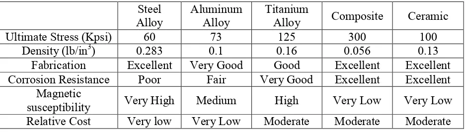
2.2.1 Pressure Hull material
Material selection for Pressure Hull must be capable to withstand pressure underwater until 2 bar. Therefore, there is comparison data of Pressure Hull materials that suitable could be used for designing this ROV.
Table 2.1: Comparison of Pressure Hull materials Steel
Alloy Aluminum Alloy Titanium Alloy Composite Ceramic
Ultimate Stress (Kpsi) 60 73 125 300 100
Density (lb/in3) 0.283 0.1 0.16 0.056 0.13
Fabrication Excellent Very Good Good Excellent Excellent Corrosion Resistance Poor Fair Very Good Excellent Excellent
Magnetic
![Figure 1.1: Work-Class ROV [1].](https://thumb-ap.123doks.com/thumbv2/123dok/567954.67149/17.612.246.383.70.254/figure-work-class-rov.webp)
![Figure 2.1: Plastic Frame [20]](https://thumb-ap.123doks.com/thumbv2/123dok/567954.67149/22.612.223.402.418.563/figure-plastic-frame.webp)
![Figure 2.2: Aluminum Frame [20]](https://thumb-ap.123doks.com/thumbv2/123dok/567954.67149/23.612.221.405.71.220/figure-aluminum-frame.webp)