INVESTIGATE ON MILD STEEL SPOT WELDING STRENGTH EFFECT BY USING DESIGN OF EXPERIMENT (DOE)
SYED MOHD AFIQ BIN SYED HASSAN
This report is submitted in partial fulfillment of the requirements for the award Bachelor of Mechanical Engineering (Design and Innovation)
Faculty of Mechanical Engineering Universiti Teknikal Malaysia Melaka
i
SUPERVISOR DECLARATION
“I hereby declare that I have read this thesis and in my opinion this report is sufficient in terms of scope and quality for the award of the degree of Bachelor of Mechanical
Engineering (Design and Innovation)”
Signature : ... Supervisor : Dr. Hady Efendy
ii
DECLARATION
“I declare that this report entitled “Investigate on Mild Steel Spot Welding Strength Effect by using Design of Experiment (DOE)” is the result of my own research except as
cited in the references”
Signature : ……….
Author’s Name : Syed Mohd Afiq Bin Syed Hassan
iii
DEDICATION
Highest Special Thankful Wishes to Both My Lovely Father and Mother
Syed Hassan Bin Syed Mohamaad &
Zaliha Bt. Anang
Also
iv
ACKNOWLEDGEMENT
Firstly, thousands of thankful wishes to ALLAH S.W.T because with His permissions, I am able to complete my Final Year Project report (BMCU 4974) without many problems and difficulties.
Next, I would like to thank my supervisor, Dr. Hady Efendi, who has willing to offer his support throughout my final year project and until this report is completed. He has never stop to support me in the best way through finding the information about my project and also on the problem solving methods. He is also very kind to contribute his time and patience to guide me to complete my project. His experience in this related topic is so valuable in my case study. Also thanks to Dr. Zulkefli and for willing to help me on using Minitab Statistical Software as this is the first time I am using the software. Lot of thanks to UiTM master student Mr. Mohammad Ridzwan Bin Abdul Rahim that were help me to teach me how to analyze the result using Minitab Statistical Software and give an idea on this study topics as I need to complete my final year project task.
v
Not to forget, thankful wishes to my family who kept supporting me in giving advices and moral support so I became stronger and more determined to finish this project. All the useful experiences that I had gained and learned really give me many experiences which will be useful when I am in working fields in future.
vi ABSTRAK
vii ABSTRACT
viii
TABLE OF CONTENT
CHAPTER TITLE PAGE
SUPERVISOR DECLARATION i
DECLARATION ii
DEDICATION iii
ACKNOWLEDGEMENT iv
ABSTRAK vi
ABSTRACT vii
TABLE OF CONTENT viii
LIST OF FIGURES xi
LIST OF TABLES xiii
LIST OF ABBREVIATIONS xiv
CHAPTER 1 INTRODUCTION
1.1 Background of the project 1
1.2 Objectives of the project 3
1.3 Problem Statement 3
1.4 Scope of the project 4
CHAPTER 2 LITERATURE REVIEW
2.1 Welding viii
ix
CHAPTER TITLE PAGE
2.3.1 Fractional Factorial Design 13 2.3.2 Response Methodology Surface (RSM) 15 2.3.3 Path of Steepest Ascent (POA) 20
CHAPTER 3 METHODOLOGY
3.1 Introduction 23
3.2 The Study 24
3.2.1 Methodology 26
CHAPTER 4 DATA AQUISITION
4.1 Introduction 27
4.2 Operational Framework 28
4.3 Specimen Selection 29
4.4 Specimen Preparation 29
4.4.1 Procedure for Specimen Preparation 31
4.5 Spot Welding Process 33
4.5.1 Resistance Spot Welding Machine 33 4.5.2 Machine Operation 34
4.6 Experiment Procedure 35
CHAPTER 5 RESULT
5.1 Introduction 36
5.2 Observation Data 36
5.3 Tensile Sheat Test 38
5.3.1 Tensile Shear Test Data Collection 38
CHAPTER 6 DISCUSSION
6.0 Introduction 41
x
CHAPTER TITLE PAGE
6.1.1 Factorial Design 43
6.2 Mathematical Modeling 51
6.3 Response Optimizer 51
6.4 Main Effects 53
CHAPTER 7 CONCLUSION AND RECOMMENDATION
7.1 Introduction 58
7.2 Conclusion 58
7.3 Recommendation 60
REFERENCES 61
xi
LIST OF FIGURES
NO. TITLE PAGE
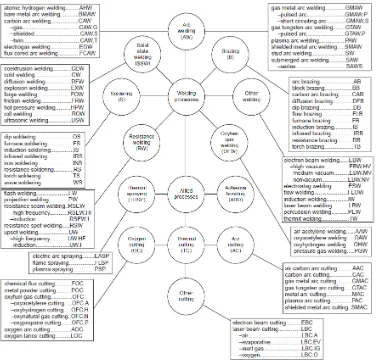
Figure 1 Master Chart of Welding and Applied Processes 6 Figure 2.1 Half fractional and full factorial design 14 Figure 2.2 Response Surface Methodology 18
Figure 2.3 Contour plot 19
Figure 2.4 Path of Steepest Ascent 20
Figure 3.1 Basic module of design process 25 Figure 3.2 Methodology flow chart of the project 25
Figure 4.1 The operational framework 28
Figure 4.2 Shape of the specimen 30
Figure 4.3 Procedure for specimen preparation flow chart 31 Figure 4.4a Resistance spot welding machine control panel 33 Figure 4.4b Resistance spot welding machine specification 33 Figure 4.5 Machine Operation Flow Chart 34 Figure 4.6 Experiment Procedure Flow Chart 35
Figure 5.1 Align specimen 38
xii
NO. TITLE PAGE
xiii
LIST OF TABLES
NO. TITLE PAGE
Table 1 Shielding Gas Selection Chart 11 Table 4.1 Dimension for test specimen 30
Table 4.2 Experiment parameters 32
Table 5.1 Variables Data 37
Table 5.2 Observation Result 37
Table 5.3 Tensile Shear Test Result 39
Table 6.1 Variable and response set 42
Table 6.2 ANOVA table for top spot welding diameter 43 Table 6.3 ANOVA table for bottom spot welding diameter 45 Table 6.4 ANOVA table for overlapped thickness 46 Table 6.5 ANOVA table for tensile stress at max load 48 Table 6.6 ANOVA table for tensile stress at yield load 49 Table 6.7 Response optimization parameters 52
Table 6.8 Global solution 52
xiv
LIST OF ABBREVIATIONS
DOE - Design of Experiment JIS - Japanese Industrial Standard BS - British Standard
twd - Top Spot Welding Diameter bwd - Bottom Spot Welding Diameter lt - Overlapped Thickness
ML - Max Load YL - Yield Load
1 CHAPTER 1
INTRODUCTION
1.1 Background of The Project
Nowadays, development of technologies provides us an extra change and awareness in technology which lead to specific changes in economic and socio-cultural values. Along with the change in values, the society becomes more focus from production to information and creativity. As the result, the consumer of this era has started to access creativity and innovation.
2
components that are weld together due to heat created by electrical resistance. This process may be performed manually, robotic or by dedicated spot welding machine. The spot welding process take the shortest time comparing to the other type of welding process.
Weld that was done by spot welding process is discrete wed locations that look like small circles on the assembled components. This weld process is not continuous. In spot welding there are several variables involve in the process such as current, pressure, human element, type of material, material thickness, welders condition, material surface and electrode tip surface. Some of the spot welding machines were use power instead current. To achieve to good quality of spot welding start with a good process design that minimize the variables during the process.
Up to now, there a lot of study on the statistical method of getting the best parameters for welders, such as (Casalino, Curcio et al.) were investigates laser welding by using statistical and Taguchi approaches.
Design of Experiment (DOE) can be defined as a systematic problem-solving approach to engineering that applies principles and technique at the data collection stage to ensure the generation of valid defensible and supportable engineering conclusions. All of this carried out can reduce expenditure of engineering runs, time and money.
3
This study aims to explore the role of the statistical modeling methods such as ANOVA, Taguchi approaches and Design of Experiment (DOE) on analyzing the parameters as the parameters that will affect spot welding quality. The primary interest is the parameters that give main effect to the welding quality and strength. The objectives of this project are:
i. To study the spot welding and the factors affecting the good spot welding quality.
ii. To analyze the spot welding parameters as the main effect of the welding strength by using statistical modeling.
iii. Using Design on Experiment to estimate good parameter of the spot welding variables.
1.3 Problem Statement
Spot welding is the major bonding technique that were widely use in automotive industry. 30% of the total amount of the joining part of the car was use spot welding as the joining technique due to difficulties to estimate welding parameters. The advantages of the resistance spot welding are high speed and suitability for automation and inclusion in high production assembly lines with other fabricating operations. Spot welding is a fast process that does not need any welding skill. Spot welding also have less probability on human error affect to the welding quality.
4
labor cost as it can be operate by unskilled operators.
1.4 Scope of The Project
This study is base on the statistical experiment modeling by combining various welding parameters. Scope of this project will be covering the case study through the literature review, journal finding and experimental for new combination of welding parameters.
By study the literature review and journal, the effect to the strength and quality of the welding in understood. These can give some information during develop a new combination of spot welding parameters. The output data is collected by a method as the mathematical model is produce during the end of this study. The method going to be use is Design of Experimental (DOE). Scopes of this project are:
1. Study will base on the best combination of parameters on mild steel by using spot welding machine as tool for welding.
2. By using Design of Experiment (DOE) method to get the combination of parameters and the number of experiment.
3. Study on power usage for spot welding, time cycle needed, and pressure use to get the best quality ant toughest strength.
4. Observe welding quality that occurs from the experiment as the reference to comparing with the welding strength to get the best quality
5 CHAPTER 2
LITERATURE REVIEW
2.1 Welding
Today, it is clearly shows that the status of welding has now changed from skill to science. A scientific understanding of the material and service requirement of the joints is necessary produce successful welds which will meet the challenge of hostile service requirements.
6
7 i. Gas Welding
• Oxyacetylene • Oxy hydrogen ii. Arc Welding
• Carbon arc • Metal arc • Submerged arc
• Inert gas welding (MIG and TIG) • Plasma arc
• Electro-slag
iii. Resistance Welding • Spot welding • Seam welding • Projection welding • Butt welding • Induction welding iv. Solid State Welding
• Friction welding • Ultrasonic welding • Explosive welding
• Forge and diffusion welding v. Thermo-chemical Welding
• Thermit welding • Atomic H2 welding
8
proximity and activity between the molecules of the pieces being joined, sufficient to cause the formation of common metallic crystals. Proximity and activity can be increase by plastic deformation or by the melting the two surfaces so that the fusion occurs.
Solid state welding, surfaces are joined by mechanically or chemically cleaned to welding. Fusion welding, the contaminants are removed from the molten pool by the use of fluxes and in vacuum or in outer space the removal of contaminant layer is quite easy and welds are formed under light pressure.
Surfaces contaminants may be organic film, absorbed gases and chemical compounds of the base metal. Heat when used as a source of energy, effectively removes organic films and adsorbed gases and only oxide film remains to be cleaned. Fluxes are used to clean the oxide film and other contaminants to form slag which floats and solidifies above the weld bead protecting the weld from further oxidation.
To protect the molten weld pool and filler metal from atmospheric contaminants such as oxygen and nitrogen, shielding gas need to be used. This shielding gas would be argon, helium, carbon dioxide or combination of argon and helium with carbon dioxide supplied externally. Carbon dioxide can also be produced by the burning of flux coating on the consumable electrode which supplies the molten filler metal to the weld pool.
9 weld-metal properties.
2.1.1 Selection of Welding Process
A weld should achieve a complete continuity between the parts being joined such that the joint is indistinguishable from the metal in which the joint is made. An ideal situation is unachievable but welds giving satisfactory service can be made in several ways. The choice of the particular welding will depends on several factors, that is:
i. Type of metal and its metallurgical characteristics ii. Type of joint, its location and welding position iii. End use of the joint
iv. Cost production v. Structural size
vi. Desired performance
vii. Experience and abilities of man power viii. Joint accessibility
ix. Joint design
x. Accuracy of assemblies required xi. Welding equipment available xii. Work sequence
xiii. Welder skill